EP0109691A1 - Trommelwurzelschneider - Google Patents
Trommelwurzelschneider Download PDFInfo
- Publication number
- EP0109691A1 EP0109691A1 EP83111664A EP83111664A EP0109691A1 EP 0109691 A1 EP0109691 A1 EP 0109691A1 EP 83111664 A EP83111664 A EP 83111664A EP 83111664 A EP83111664 A EP 83111664A EP 0109691 A1 EP0109691 A1 EP 0109691A1
- Authority
- EP
- European Patent Office
- Prior art keywords
- drum
- lantern
- knife
- arms
- holders
- Prior art date
- Legal status (The legal status is an assumption and is not a legal conclusion. Google has not performed a legal analysis and makes no representation as to the accuracy of the status listed.)
- Granted
Links
Images


Classifications
-
- C—CHEMISTRY; METALLURGY
- C13—SUGAR INDUSTRY
- C13B—PRODUCTION OF SUCROSE; APPARATUS SPECIALLY ADAPTED THEREFOR
- C13B5/00—Reducing the size of material from which sugar is to be extracted
- C13B5/06—Slicing sugar beet
-
- B—PERFORMING OPERATIONS; TRANSPORTING
- B23—MACHINE TOOLS; METAL-WORKING NOT OTHERWISE PROVIDED FOR
- B23D—PLANING; SLOTTING; SHEARING; BROACHING; SAWING; FILING; SCRAPING; LIKE OPERATIONS FOR WORKING METAL BY REMOVING MATERIAL, NOT OTHERWISE PROVIDED FOR
- B23D35/00—Tools for shearing machines or shearing devices; Holders or chucks for shearing tools
- B23D35/008—Means for changing the cutting members
-
- C—CHEMISTRY; METALLURGY
- C13—SUGAR INDUSTRY
- C13B—PRODUCTION OF SUCROSE; APPARATUS SPECIALLY ADAPTED THEREFOR
- C13B5/00—Reducing the size of material from which sugar is to be extracted
- C13B5/08—Knives; Adjustment or maintenance thereof
Definitions
- the present invention relates to a drum root cutter used to cut beets into cossettes from which sugar is extracted by diffusion.
- a root cutter comprises a drum with a substantially horizontal axis, open on a front side, this drum being mounted in rotation on a frame equipped with a feed hopper opening on the open side of the drum.
- the drum is formed by a wheel or lantern which is integral with a shaft driven in rotation and to which are fixed in cantilever a multitude of axial arms distributed uniformly around the periphery of the lantern and projecting towards the open side of the drum, said lantern arms being joined by a circle at their free end.
- the lantern arms receive knife holders to which knives are attached which, when the drum is rotated, cut into beets the beets in the drum.
- the identical knife holders are double and each have two rows of different knives called knives A and knives B.
- These two kinds of knives are distinguished by the offset of a half step their zigzag cutting edges, offset which is necessary to allow the beets to be cut into V-shaped pods with equal wings called ridge pods.
- both the attachment of the knives to the knife holders and the attachment of the knife holders to the lantern arms is carried out using screws, in reciprocal positions well determined along the axis of the drum.
- the change of the double knife holders therefore heavy includes the operations of loosening the fixing screws of the knife holders to the lantern arms, unlocking the knife holders from the lantern arms, removing the knife holders, introducing the new knife holders and tightening the fixing screws, these operations are carried out through a front opening and a lateral opening of the casing surrounding the drum. These are painful and time-consuming operations.
- the contact surfaces of the knife holders and lantern arms must be machined with great precision in order to guarantee the knives a well-defined position necessary for obtaining a good quality of chips.
- the present invention relates to a drum root cutter using, on all identical knife holders, a single type of knife, even possibly for different beet qualities.
- the subject of the invention is also a drum root cutter clearly less subject to wear than known root cutters.
- the invention further relates to a drum root cutter which does not involve complicated machining. and very high precision of the contact surfaces of the knife holders and lantern arms.
- the invention also relates to a drum root cutter on which the change of the knife holders is carried out in a simple and rapid manner.
- the invention finally aims to automate to a large extent the change of knife holders on a drum root cutter.
- the lantern arms have a circular profile and each knife holder with a single row of knives has, on each of its two opposite longitudinal edges, a groove in an arc of a circle complementary to the profile of the lantern arms of so that each knife holder can be engaged axially between two neighboring lantern arms and is retained on said arms both outwards and inwards of the drum, and that the knife holders and the lantern include means for positioning axially the knife holders on the lantern.
- the lantern arms of circular section and the arcuate grooves of the knife holders do not involve complicated and high-precision machining and nevertheless ensure, thanks to their complementary shapes, precise radial positioning of the knife holders, therefore knives, without additional means such as screws for fixing the knife holders to the lantern arm.
- the installation and removal of the knife holders by axial sliding on the lantern arms are simple operations, especially since the knife holders with a single row of knives are light.
- the means of axial positioning of the knife holders on the lantern make it possible to use, for a root cutter, a single type of knife holder and a single type of knife and nevertheless to obtain an axial offset of the successive knives.
- each of the two opposite grooves of each knife holder extends over an arc of a circle of more than 90 ° with an undercut part towards the outside of the drum on an arc of a circle substantially equal to 90 °.
- two neighboring knife holders surround the intermediate lantern arm almost on the entire circumference half facing inward of the drum and thus prevent the beets from coming into contact with the lantern arm, which eliminates any risk of wear there.
- the means for axially positioning the knife holders on the lantern advantageously comprise axial stops on the lantern and latching devices keeping the knife holders pressed against said stops. These latching devices do not have to bear considerable effort and their actuation is simple and easy.
- the means for axial positioning of the knife holders on the lantern comprise axial stops of different thicknesses, preferably exchangeable, on the lantern and snap-in devices tightening the knife holders axially against said stops of different thicknesses.
- the latching device used to clamp the knife holders against the axial stops advantageously comprises, on the knife holder or the lantern, for each knife holder, at least one latch with double ramp, biased by a spring, and on the lantern or the knife holder, a latching shoulder also with a double ramp for said latch, allowing engagement and release by a simple axial force exerted on the knife holder, in one direction or the other, and the axial clamping against the stop, regardless of differences in thickness of the latter.
- the change of the knife holders is thus extremely simple and rapid since it suffices, to remove a knife holder from the lantern, to exert an axial force on the knife holder to release the latch from the shoulder and thus remove by axial sliding of the lantern knife holder, while to put a knife holder on the lantern, it is sufficient to engage it by axial sliding on the lantern, between two lantern arms, the axial positioning taking place at the end of this axial positioning movement, by engagement of the latch behind the latching shoulder.
- the drum root cutter advantageously comprises a device for stepping the drum step by step, comprising a first jack carrying means capable of cooperating in the direction of thrust of said jack with a lantern arm, in order to move the drum angularly by one step, and a second jack for bringing said means into position of cooperation with the lantern arm during the pushing movement of said first jack and bringing them out of the posi tion of cooperation with the lantern arm during the withdrawal movement of said first cylinder.
- This step-by-step rotation device allows precise intermittent rotation of the drum during the successive change of the knife holders.
- a device for angular positioning of the drum preferably comprising a locking cylinder mounted on the frame in a substantially radial position relative to the drum. and carrying means cooperating with a lantern arm to block said arm when the jack is supplied in one direction and release said arm when the jack is supplied in the other direction.
- Said means provided on the stepping rotation device and the positioning device for cooperating with the lantern arms under the action of the jacks are advantageously designed so that they cannot engage between two neighboring lantern arms and come, under the action of the jacks, automatically in the position of cooperation with the lantern arms.
- the root cutter according to the invention may advantageously include an automatic device for introducing a knife holder and for automatically removing a holder knives.
- This automatic insertion and removal device involves very precise angular positioning of the drum, positioning which can be advantageously achieved by the step-by-step rotation device and the positioning device as defined above.
- This automatic introduction and removal device comprises a loading cradle and an unloading cradle mounted in a fixed position on the open side of the drum, the loading cradle being intended to receive a knife holder to be introduced, put in place of the outside on the cradle, and the unloading cradle being intended to receive a knife holder removed from the drum and to be unloaded to the outside.
- These measures further comprises means for inserting a knife holder into the drum and for removing a knife holder from the drum, said means being jointly moved back and forth along the axis of the drum, to push the knife holder of the loading cradle into the drum during the forward movement and to remove a knife holder of the drum on the unloading cradle during the return movement.
- fig. 8 is a section along VIII-VIII of FIG. 7.
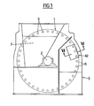
- the drum root cutter illustrated by the drawings comprises, according to FIG. 1, a drum 1 with a horizontal axis, mounted in rotation on a mechanically welded frame referenced 3 as a whole.
- the drum 1 is, in a manner known per se, composed of a wheel or lantern 4 integral with the shaft 2 driven in rotation and to which are fixed in cantilever a multitude of lantern arms parallel to the axis of the drum 5.
- the drum 1 is therefore open on the front side opposite to the lantern 4.
- a flange 6 In front of the open side of the drum 1, a flange 6 is installed on the frame 3. This flange 6 carries a feed hopper 7 opening into the drum 1, on one side of the shaft 2 . This flange 6 carries, moreover, a wall known as a "comma" compression on the other side of the shaft 2, inside the drum, a fixed disc 8 located, inside the drum, in front of the lantern 4 and a fixed cover sheet 9 which internally covers the drum in the upper part.
- This general structure of the root cutter according to the invention corresponds substantially to that of known drum root cutters.
- the lantern arms 5 which receive the knife holders on which the knives are fixed, reducing the beets into cossettes in the lower part of the drum, during the rotation of the latter, consist of massive cylindrical bars fixed in the lantern 4
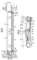
- each knife holder 11 of generally rectangular shape, held between two neighboring lantern arms 5, is equipped with a single row of knives 12 and a strip 13 for adjusting the depth of cut, that is to say - say the thickness of the chips.
- the evacuation of the chips to the outside of the drum is effected by an opening 14 provided in the knife holder 11 over the entire length of the knives 12.
- Each knife holder 11 has, on each of its two opposite longitudinal edges, a groove 15 in an arc of a circle, having a profile complementary to that of the lantern arms 5.
- Each groove 15 extends over an arc of a circle of more than 90 ° so as to present an undercut part inwards and outwards, which means that the knife holders are held relative to the arms 5 both inwards and outwards of the drum.
- each knife holder 11 covers the two lantern arms 5 neighbors between which it is held, on the inside of the drum up to the vicinity of the radial plane passing through the axis of the arm 5 considered. Therefore, as shown in FIG. 4, the neighboring knife holders 11 together cover almost completely towards the inside of the drum the lantern arm 5 which is common to them.
- the knife holders 11 which are thus positioned radially inwards and outwards from the drum, thanks to the complementary shape of their grooves 15 and the lantern arms 5,. are therefore slidably mounted on the lantern arms 5 with a view to their installation and their removal from the lantern arms by translation along the axis of the drum.
- the axial positioning of the knife holders 11 relative to the drum 1 is effected by means of stops 16, 16a fixed with screws 17 to the lantern 4 of the drum 1.
- Each knife holder 11 is held in abutment against its stop 16, 16a by a latching device 18 provided at the opposite end of the knife holder 11.
- This latching device 18 comprises two latches 19 with double ramp, mounted transversely on the knife holder 11 and biased in opposite directions by a common spring 20.
- Each latch 19 cooperates, when the knife holder 11 arrives in the support position against the stop 16, 16a, with a shoulder 21 with double ramp, formed at the free end of each arm of lantern 5.
- each latch 19 and each shoulder 21 Thanks to the double ramp of each latch 19 and each shoulder 21, the two latches 19 of each knife holder 11 cross themselves the two shoulders 21 of the two lantern arms 5, during the axial insertion of the door -knives 11 between the two arms 5 and then ensure the support of the knife holder 11 against the stop 16, 16a. Conversely, to remove a knife holder 11 between two lantern arms 5, it suffices to pull towards the open side of the drum 1 on the knife holder 11 to release the latches 19 from the shoulders 21, the holder knife 11 which can then be completely extracted by axial sliding.
- the axial stops 16, 16a successive sives alternately have different thicknesses.
- This difference in thickness which is visible between the stop 16 and the stop 16a in FIG. 2 corresponds to a half-step or a half-division of the zigzag cutting edges of the knives.
- the successive knives must be shifted by half a step in order to obtain ridge caps, that is to say V caps with equal wings.
- This half-step offset which is carried out in the usual way by the use of two types of knives on the same knife holder is therefore produced here only by the axial positioning stops 16, 16a while the knives and the knife holders fitted to the root cutter are all identical.
- the operation of the latching device 18 is not affected by this axial offset of the successive knife holders thanks to the fact that the notch 22 which defines the retaining ramp of the shoulder 21 is deep enough for the latch 19 to be able to bear on this ramp retained in the two axial positions determined by the stops 16, 16a of different thicknesses.
- the different lantern arms 5 are connected to each other, at their free end, by an outer circle 23 arranged so as not to hinder the engagement and axial disengagement of the knife holders 11 between the lantern arms 5.
- Longitudinal wear plates 24 are attached to each knife holder 11, on the parts exposed to contact with beets, that is to say between the adjusting strip 13 and a longitudinal edge, and between the heel of the knives 12 and the other longitudinal edge. Furthermore, wear plates 25 in the form of an arc are attached to the transverse end edges of the knife holder 11. The wear plate 25 fixed on the end of the knife holder 11 which comes to bear against the stop 16 (right end in fig. 3) is arranged on the knife holder 11 so that, whatever the stop 16, 16a, said dish 25 is always set back (to the right in fig. 3) by relative to the fixed inner disc 8. Thus, it is ensured that the beets in the vicinity of this ends are also reduced in pods by the knives 12 rather than being reduced in grating by abrasion.
- the change of the knife holders is carried out periodically and carries each time on all the knife holder of the drum. It is therefore necessary, in order to change all of the knife holders, to successively bring all the knife holders of the drum into a change position, to remove each time the knife holder which is in the change position and to replace it. by a new knife holder.
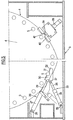
- Fig. 5 illustrates a step-by-step rotation and positioning device making it possible to bring the various knife-holders of the drum successively to the changing position.
- the step-by-step rotation device comprises a thrust cylinder 26 whose cylinder 27 is articulated on the frame 3 by an axis 28 parallel to the axis of the drum 4.
- the piston rod 29 of the cylinder 26 carries, at its end, a fitting 30 having a further 31 in its face 32 which is parallel to the piston rod 29 and is turned towards the drum 4.
- the notch 32 is defined by a profile in an arc of a circle over more than 90 °, on the side facing the jack 26, and by an oblique rectilinear side on the opposite side, this rectilinear side being such that the notch 31 widens from its bottom to its outlet on the face 32.
- Another cylinder 33 is installed in the same vertical plane as the cylinder 26, the cylinder 34 of the cylinder 33 being articulated by an axis 35 parallel to the axis of the drum 4 on the frame 3.
- the piston rod 36 of the cylinder 33 is articulated by an axis 37 parallel to the axis of the drum 4 on the fitting 30.
- the two jacks 26, 33 are arranged in the plane of the rear ends of the lantern arms 5 projecting somewhat from the lantern 4 (see fig. 2 and 3), in positions such as one with respect to 1 1 other and relative to the drum 4 only when the piston rods 29 and 36 are completely removed in the cylinders 27 and 34 of the jacks 26 and 33, the fitting 30 can, by a thrust exerted by the jack 33, be brought to cooperate by its notch 31, with a lantern arm 5. A push exerted by the jack 26 then allows the drum 4 to rotate by one step.
- the angular positioning device which serves to maintain the drum in a well-defined angular position while the fitting 30 of the step-by-step rotation device is not engaged with a lantern arm 5 comprises a jack 38 installed at a fixed position on the frame 3, in a radial position relative to the drum 4.
- the piston rod 39 of the jack 38 carries a fitting 40 having a notch 41 substantially semicircular, opening towards the drum 4 and capable of engaging on the rear end projecting from a lantern arm 5 when the fitting 40 is advanced towards the drum 4 under the action of the jack 38.
- the jack 38 is arranged, relative to the jacks 26 and 33, in such a way that an arm lantern 5 is located opposite the notch 41 when the drum 4 has been advanced by one step by the jack 26.
- the jacks 33 and 38 can be low pressure jacks since they do not have to exert a considerable pushing force while the jack 26, the pushing of which turns the drum 4 is advantageously a jack with high pressure.
- step-by-step rotation device which only intervenes for the change of the knife holders rotates the drum in the opposite direction to the direction of rotation during normal operation.
- the fittings 30 and 40 have, in the circumferential direction of the drum 4, each a length greater than the distance between two successive lantern arms 5.
- the two fittings 30 and 40 are further provided with a material having good sliding properties on their side facing the drum 4.
- This step-by-step rotation and positioning device is particularly advantageous when the drum root cutter is equipped with an automatic device for removing and inserting the knife holders, as illustrated in FIGS. 6, 7 and 8.
- This automatic withdrawal and introduction device referenced 42 as a whole, is mounted in a fixed position in front of the open side of the drum, on the flange 6.
- the device 42 located opposite the upper part of the drum comprises a support structure formed mainly by two guide rails 43, 44. And two bars 45 and 46 parallel to the axis of the drum, the whole being fixed on the flange 6.
- the reciprocal position of the rails 43, 44 and the bars 45, 46 appears in FIG. 8.
- the two rails 43 and 44 are arranged, inside the circle described by the lantern arms 5 during the rotation of the drum 1, in a plane intersecting said circle.
- the two bars 45 and 46 are arranged on said circle, at a reciprocal distance corresponding to the distance between two lantern arms 5.
- the bar 45 is located below the lower rail 46, while the bar 47 is located at a height between the bottom rail 43 and the top rail 44.
- the two rails 43, 44 have, in their faces facing one another, each a groove for guiding the wheels 47 of a carriage 48 movable back and forth along the rails 43 and 44 under the action of a jack 49.
- the loading cradle 50 is intended to receive a knife holder to be introduced in the drum 1, while the unloading cradle 51 is intended to receive a knife holder removed from the drum 1.
- the position of the two knife holders 11 in question on the loading cradle 50 and the unloading cradle 51 has been indicated in dash.
- the knife holder 11 on the loading cradle 50 is engaged from the outside (from the right in Fig. 8) by one of its arcuate grooves on the lower bar 45 which has a circular profile corresponding to that of the lantern arms 5 and is pressed in an inclined position relative to the vertical against the rail lower 43.
- the knife holder 11 on the unloading cradle 51 is engaged by one of its grooves in an arc on the lower bar 46 which also has a circular profile corresponding to that of the lantern arms 5 and is pressed in an inclined position relative to the vertical against the rail 44.
- the upper bar 46 has, over a length slightly greater than the length of the knife holders 11, a cutout 52 involving more than the lower half of its section. This cutout 52 is necessary to allow the installation of the knife holder 11 on the loading cradle 50.
- the carriage 48 carries, opposite the loading cradle 50, a pusher 53 urged by a spring 54. Opposite the unloading cradle 51, the carriage 48 carries a hook 55 urged by a spring 56 in the hooking direction, at know down in fig. 6.
- This hook 55 which has a ramp at its free end is intended to cooperate with a nose 57 (see also fig. 3) provided on each knife holder 11, below the latching device 18, in the withdrawn position of the carriage 48, as illustrated in FIGS. 6 and 7, the hook 55 is brought into the release position against the action of the spring 56, by a fixed cam 58.
- the drum 1 is brought in, by the step-by-step rotation and positioning device illustrated in FIG. 5, in an angular position in which the two bars 45 and 46 of the device 42 are aligned with two neighboring lantern arms 5.
- the loading cradle 50 and the unloading cradle 51 of the device 42 being empty, the actuator 49 is then actuated to move the carriage 48 towards the drum 1 (to the right in FIGS. 6 and 7), until the hook 55 engages behind the nose 57 of the knife holder 11 located in front of the cradle 51.
- the pusher 53 abutted against the neighboring knife holder 11, located in front of the loading cradle 50, the compression of its spring 54 then allowing the hook 55 to be engaged behind the nose 57 of the other knife holder 11.
- Drum 1 is advanced by one step, to bring the two lantern arms 5 between which was the knife holder previously removed, in alignment with the two bars 45 and 46, that is to say opposite the loading cradle 50 and the new knife holder 11 installed on this cradle.
- the actuator 49 is then actuated to move the carriage 48 towards the drum 1 and thus engage the knife holder 11 located on the loading cradle 50 in the drum 1, the spring 54 of the pusher 53 being powerful enough to overcome the resistance exerted by the latching device 18, so that the knife holder inserted is positioned axially against its stop 16.
- the hook 55 engages behind the nose 57 of the tool holder 11 neighbour.
- the actuator 49 is then actuated in the opposite direction, to move the carriage 48 to the left and thus remove from the drum 1 the knife holder 11 on which the hook 55 is engaged.
- This cycle is then repeated as many times as the drum has knife holders.
- the stroke of the carriage 48 must be reduced so that the hook 55 does not engage behind the nose 57 of the knife holder 11 then being located opposite the cradle unloading 51.
- this knife holder is the first to have been changed during the same cycle.
- the jack 49 has two end of travel positions and a counter is provided to trigger the change of end of travel position during the last insertion movement.
- the control of the device for removing and inserting 42 from the knife holders 11 can advantageously be combined with the control of the device for step-by-step rotation and positioning for the automation and safety of the sequences of a complete cycle. change of knife holder.
Landscapes
- Chemical & Material Sciences (AREA)
- Life Sciences & Earth Sciences (AREA)
- Biochemistry (AREA)
- Organic Chemistry (AREA)
- Engineering & Computer Science (AREA)
- Mechanical Engineering (AREA)
- Apparatuses For Bulk Treatment Of Fruits And Vegetables And Apparatuses For Preparing Feeds (AREA)
- Drying Of Solid Materials (AREA)
- Freezing, Cooling And Drying Of Foods (AREA)
- Cereal-Derived Products (AREA)
Priority Applications (1)
| Application Number | Priority Date | Filing Date | Title |
|---|---|---|---|
| AT83111664T ATE27969T1 (de) | 1982-11-23 | 1983-11-22 | Trommelwurzelschneider. |
Applications Claiming Priority (2)
| Application Number | Priority Date | Filing Date | Title |
|---|---|---|---|
| FR8219607A FR2536417A1 (fr) | 1982-11-23 | 1982-11-23 | Coupe-racines a tambour, en particulier pour betteraves a sucre |
| FR8219607 | 1982-11-23 |
Publications (2)
| Publication Number | Publication Date |
|---|---|
| EP0109691A1 true EP0109691A1 (de) | 1984-05-30 |
| EP0109691B1 EP0109691B1 (de) | 1987-06-24 |
Family
ID=9279432
Family Applications (1)
| Application Number | Title | Priority Date | Filing Date |
|---|---|---|---|
| EP83111664A Expired EP0109691B1 (de) | 1982-11-23 | 1983-11-22 | Trommelwurzelschneider |
Country Status (4)
| Country | Link |
|---|---|
| EP (1) | EP0109691B1 (de) |
| AT (1) | ATE27969T1 (de) |
| DE (2) | DE109691T1 (de) |
| FR (1) | FR2536417A1 (de) |
Cited By (6)
| Publication number | Priority date | Publication date | Assignee | Title |
|---|---|---|---|---|
| FR2635275A1 (fr) * | 1988-08-13 | 1990-02-16 | Putsch & Co H | Dispositif de remplacement des porte-couteaux de coupe-racines a tambour |
| EP0505676A1 (de) * | 1991-03-26 | 1992-09-30 | PESSA S.p.A. | Vorrichtung zum Wechseln von Messern in Holzzerspanungsmaschinen |
| FR2676185A1 (fr) * | 1991-05-07 | 1992-11-13 | Pallmann Kg Maschf | Procede et dispositif de changement automatique de lames reaffutables dans des machines a travailler le bois avec enlevement de copeaux. |
| FR2723705A1 (fr) * | 1994-08-17 | 1996-02-23 | Pallmann Kg Maschf | Dispositif de broyage pour la production de particules en forme de prismes et en particulier en forme de cubes a partir de materiaux pouvant etre coupes |
| WO2011116482A1 (de) * | 2010-03-22 | 2011-09-29 | Bucher Unipektin Ag | Messerbett für eine vorrichtung zum zerkleinern von organischen substanzen |
| CN105415417A (zh) * | 2015-11-02 | 2016-03-23 | 泉州市永茂电子科技有限公司 | 一种滚筒式皂角刺剪取设备 |
Citations (5)
| Publication number | Priority date | Publication date | Assignee | Title |
|---|---|---|---|---|
| FR325314A (fr) * | 1902-10-15 | 1903-04-25 | Maguin Alfred | Perfectionnements apportés aux coupe-racines pour sucrerie et distillerie |
| US2148922A (en) * | 1937-12-18 | 1939-02-28 | Bachofner Albert | Beet-cutting machine |
| US2197192A (en) * | 1939-05-29 | 1940-04-16 | Spreckels Sugar Company | Adjusting apparatus |
| FR860489A (fr) * | 1939-06-28 | 1941-01-16 | Sucreries Ternynck | Perfectionnements aux coupe-racines, notamment aux machines pour découper les betteraves en cossettes |
| FR1252370A (fr) * | 1960-03-17 | 1961-01-27 | Fives Lille Cail | Boîte à couteaux pour turbo-coupe-racines de sucreries |
-
1982
- 1982-11-23 FR FR8219607A patent/FR2536417A1/fr active Granted
-
1983
- 1983-11-22 AT AT83111664T patent/ATE27969T1/de not_active IP Right Cessation
- 1983-11-22 DE DE198383111664T patent/DE109691T1/de active Pending
- 1983-11-22 DE DE8383111664T patent/DE3372215D1/de not_active Expired
- 1983-11-22 EP EP83111664A patent/EP0109691B1/de not_active Expired
Patent Citations (5)
| Publication number | Priority date | Publication date | Assignee | Title |
|---|---|---|---|---|
| FR325314A (fr) * | 1902-10-15 | 1903-04-25 | Maguin Alfred | Perfectionnements apportés aux coupe-racines pour sucrerie et distillerie |
| US2148922A (en) * | 1937-12-18 | 1939-02-28 | Bachofner Albert | Beet-cutting machine |
| US2197192A (en) * | 1939-05-29 | 1940-04-16 | Spreckels Sugar Company | Adjusting apparatus |
| FR860489A (fr) * | 1939-06-28 | 1941-01-16 | Sucreries Ternynck | Perfectionnements aux coupe-racines, notamment aux machines pour découper les betteraves en cossettes |
| FR1252370A (fr) * | 1960-03-17 | 1961-01-27 | Fives Lille Cail | Boîte à couteaux pour turbo-coupe-racines de sucreries |
Cited By (6)
| Publication number | Priority date | Publication date | Assignee | Title |
|---|---|---|---|---|
| FR2635275A1 (fr) * | 1988-08-13 | 1990-02-16 | Putsch & Co H | Dispositif de remplacement des porte-couteaux de coupe-racines a tambour |
| EP0505676A1 (de) * | 1991-03-26 | 1992-09-30 | PESSA S.p.A. | Vorrichtung zum Wechseln von Messern in Holzzerspanungsmaschinen |
| FR2676185A1 (fr) * | 1991-05-07 | 1992-11-13 | Pallmann Kg Maschf | Procede et dispositif de changement automatique de lames reaffutables dans des machines a travailler le bois avec enlevement de copeaux. |
| FR2723705A1 (fr) * | 1994-08-17 | 1996-02-23 | Pallmann Kg Maschf | Dispositif de broyage pour la production de particules en forme de prismes et en particulier en forme de cubes a partir de materiaux pouvant etre coupes |
| WO2011116482A1 (de) * | 2010-03-22 | 2011-09-29 | Bucher Unipektin Ag | Messerbett für eine vorrichtung zum zerkleinern von organischen substanzen |
| CN105415417A (zh) * | 2015-11-02 | 2016-03-23 | 泉州市永茂电子科技有限公司 | 一种滚筒式皂角刺剪取设备 |
Also Published As
| Publication number | Publication date |
|---|---|
| FR2536417A1 (fr) | 1984-05-25 |
| ATE27969T1 (de) | 1987-07-15 |
| DE3372215D1 (en) | 1987-07-30 |
| DE109691T1 (de) | 1984-12-20 |
| FR2536417B1 (de) | 1985-04-12 |
| EP0109691B1 (de) | 1987-06-24 |
Similar Documents
| Publication | Publication Date | Title |
|---|---|---|
| EP0230841A1 (de) | Maschine zur automatischen Herstellung von Fleisch- und/oder Gemüsespiessen | |
| EP0078232B1 (de) | Aufspiessvorrichtung zum Herstellen von Fleischspiessen und/oder anderer Nahrungsmittel | |
| FR2488169A1 (fr) | Ensemble d'un coulisseau et d'un porte-outil pour tour vertical ou machine analogue | |
| EP0109691B1 (de) | Trommelwurzelschneider | |
| FR2738176A1 (fr) | Decoupeuse non rotative et indexable | |
| FR2676185A1 (fr) | Procede et dispositif de changement automatique de lames reaffutables dans des machines a travailler le bois avec enlevement de copeaux. | |
| FR2635997A1 (fr) | Systeme de transfert a rotation | |
| EP0098451B1 (de) | Maschine zur Herstellung von Fleischspiessen | |
| EP0279741B1 (de) | Verfahren und Vorrichtung zum Schneiden von verstrahlten Brennelementen in horizontaler Richtung unter Verwendung eines Messerschlittens | |
| EP0094883B1 (de) | Schervorrichtung für bestrahlte Brennstoffbündel | |
| CH682995A5 (fr) | Dispositif d'interception de feuilles déposées sur le haut d'une pile dans une machine de production d'emballages. | |
| EP2896584B1 (de) | Qualitätskontrollanlage einer Reihe von Artikeln, insbesondere von Flaschen | |
| FR2642939A1 (fr) | Procede et dispositifs d'embrochement pour machine a brochettes | |
| FR2573694A1 (fr) | Procede pour le changement des porte-couteaux des machines a plateau de coupe et machine a plateau de coupe porte-couteaux pour la mise en oeuvre de ce procede | |
| EP0067760B1 (de) | Einrichtung zum Verteilen, Orientieren und Positionieren von Achsen zu einer automatischen Maschine | |
| EP1120183A2 (de) | Zwischenplatte zum Einsetzen in einem Schneidschlitz | |
| WO1992008359A1 (fr) | Machine pour la preparation de brochettes | |
| EP0155881A1 (de) | Verfahren und Vorrichtung zum Entkrusten und Schneiden von Käselaiben | |
| EP3318397B1 (de) | Förderverfahren einer last, insbesondere eines pressinstruments, entsprechende fördervorrichtung und presse, die mit einer solchen vorrichtung ausgestattet ist | |
| BE1024594B1 (fr) | Bandage annulaire monobloc pour diffuseur | |
| EP0242490B1 (de) | Vorrichtung und Verfahren zur Einführung von Proben in eine Einrichtung | |
| EP0094882A1 (de) | Maschine zum Zusammendrücken von Brennstoffbündeln und zur Abnahme von dessen Endstücken | |
| FR2478513A1 (fr) | Dispositif d'alimentation automatique de barres dans une machine-outil | |
| FR2775925A1 (fr) | Dispositif pour realiser le clivage de blocs de schistes ou ardoisiers de forme parallelepipedique | |
| EP2414244B1 (de) | Anlage und verfahren zum verpacken von komponenten in form von streifen |
Legal Events
| Date | Code | Title | Description |
|---|---|---|---|
| PUAI | Public reference made under article 153(3) epc to a published international application that has entered the european phase |
Free format text: ORIGINAL CODE: 0009012 |
|
| AK | Designated contracting states |
Designated state(s): AT BE DE GB IT NL SE |
|
| ITCL | It: translation for ep claims filed |
Representative=s name: STUDIO VETTOR GALLETTI |
|
| TCAT | At: translation of patent claims filed | ||
| 17P | Request for examination filed |
Effective date: 19840724 |
|
| TCNL | Nl: translation of patent claims filed | ||
| DET | De: translation of patent claims | ||
| RAP1 | Party data changed (applicant data changed or rights of an application transferred) |
Owner name: MAGUIN S.A. |
|
| ITF | It: translation for a ep patent filed |
Owner name: VETTOR GALLETTI DI SAN CATALDO |
|
| GRAA | (expected) grant |
Free format text: ORIGINAL CODE: 0009210 |
|
| AK | Designated contracting states |
Kind code of ref document: B1 Designated state(s): AT BE DE GB IT NL SE |
|
| REF | Corresponds to: |
Ref document number: 27969 Country of ref document: AT Date of ref document: 19870715 Kind code of ref document: T |
|
| REF | Corresponds to: |
Ref document number: 3372215 Country of ref document: DE Date of ref document: 19870730 |
|
| PLBE | No opposition filed within time limit |
Free format text: ORIGINAL CODE: 0009261 |
|
| STAA | Information on the status of an ep patent application or granted ep patent |
Free format text: STATUS: NO OPPOSITION FILED WITHIN TIME LIMIT |
|
| 26N | No opposition filed | ||
| ITTA | It: last paid annual fee | ||
| EAL | Se: european patent in force in sweden |
Ref document number: 83111664.5 |
|
| PGFP | Annual fee paid to national office [announced via postgrant information from national office to epo] |
Ref country code: BE Payment date: 20001204 Year of fee payment: 18 |
|
| PGFP | Annual fee paid to national office [announced via postgrant information from national office to epo] |
Ref country code: NL Payment date: 20011016 Year of fee payment: 19 |
|
| PGFP | Annual fee paid to national office [announced via postgrant information from national office to epo] |
Ref country code: AT Payment date: 20011017 Year of fee payment: 19 |
|
| PGFP | Annual fee paid to national office [announced via postgrant information from national office to epo] |
Ref country code: SE Payment date: 20011018 Year of fee payment: 19 |
|
| PGFP | Annual fee paid to national office [announced via postgrant information from national office to epo] |
Ref country code: DE Payment date: 20011115 Year of fee payment: 19 |
|
| PGFP | Annual fee paid to national office [announced via postgrant information from national office to epo] |
Ref country code: GB Payment date: 20011116 Year of fee payment: 19 |
|
| PG25 | Lapsed in a contracting state [announced via postgrant information from national office to epo] |
Ref country code: NL Free format text: LAPSE BECAUSE OF NON-PAYMENT OF DUE FEES Effective date: 20011130 Ref country code: BE Free format text: LAPSE BECAUSE OF NON-PAYMENT OF DUE FEES Effective date: 20011130 |
|
| REG | Reference to a national code |
Ref country code: GB Ref legal event code: IF02 |
|
| BERE | Be: lapsed |
Owner name: MAGUIN S.A. Effective date: 20011130 |
|
| NLV4 | Nl: lapsed or anulled due to non-payment of the annual fee |
Effective date: 20020601 |
|
| PG25 | Lapsed in a contracting state [announced via postgrant information from national office to epo] |
Ref country code: GB Free format text: LAPSE BECAUSE OF NON-PAYMENT OF DUE FEES Effective date: 20021122 Ref country code: AT Free format text: LAPSE BECAUSE OF NON-PAYMENT OF DUE FEES Effective date: 20021122 |
|
| PG25 | Lapsed in a contracting state [announced via postgrant information from national office to epo] |
Ref country code: SE Free format text: LAPSE BECAUSE OF NON-PAYMENT OF DUE FEES Effective date: 20021123 |
|
| PG25 | Lapsed in a contracting state [announced via postgrant information from national office to epo] |
Ref country code: DE Free format text: LAPSE BECAUSE OF NON-PAYMENT OF DUE FEES Effective date: 20030603 |
|
| EUG | Se: european patent has lapsed | ||
| GBPC | Gb: european patent ceased through non-payment of renewal fee |