EP0109205A2 - Procédé et appareil d'imagerie de tomogrammes traités par ordinateur - Google Patents
Procédé et appareil d'imagerie de tomogrammes traités par ordinateur Download PDFInfo
- Publication number
- EP0109205A2 EP0109205A2 EP83306359A EP83306359A EP0109205A2 EP 0109205 A2 EP0109205 A2 EP 0109205A2 EP 83306359 A EP83306359 A EP 83306359A EP 83306359 A EP83306359 A EP 83306359A EP 0109205 A2 EP0109205 A2 EP 0109205A2
- Authority
- EP
- European Patent Office
- Prior art keywords
- detectors
- data
- functioning
- radiation
- detector
- Prior art date
- Legal status (The legal status is an assumption and is not a legal conclusion. Google has not performed a legal analysis and makes no representation as to the accuracy of the status listed.)
- Withdrawn
Links
- 238000000034 method Methods 0.000 title claims abstract description 44
- 238000013170 computed tomography imaging Methods 0.000 title 1
- 238000002591 computed tomography Methods 0.000 claims abstract description 62
- 230000005855 radiation Effects 0.000 claims description 30
- 238000003384 imaging method Methods 0.000 claims description 9
- 230000002238 attenuated effect Effects 0.000 claims description 5
- 238000001914 filtration Methods 0.000 claims description 3
- 238000003325 tomography Methods 0.000 claims 3
- 238000012935 Averaging Methods 0.000 abstract description 9
- 239000013078 crystal Substances 0.000 description 8
- 238000013461 design Methods 0.000 description 8
- 230000008569 process Effects 0.000 description 7
- 238000013507 mapping Methods 0.000 description 6
- 239000003570 air Substances 0.000 description 5
- 238000004364 calculation method Methods 0.000 description 5
- 238000004378 air conditioning Methods 0.000 description 4
- 230000008901 benefit Effects 0.000 description 4
- 238000004458 analytical method Methods 0.000 description 3
- 238000001816 cooling Methods 0.000 description 3
- 230000007812 deficiency Effects 0.000 description 3
- 230000007257 malfunction Effects 0.000 description 3
- 238000005259 measurement Methods 0.000 description 3
- 239000012080 ambient air Substances 0.000 description 2
- 238000010420 art technique Methods 0.000 description 2
- 239000002826 coolant Substances 0.000 description 2
- 230000006870 function Effects 0.000 description 2
- 239000007788 liquid Substances 0.000 description 2
- 238000012986 modification Methods 0.000 description 2
- 230000004048 modification Effects 0.000 description 2
- 238000012545 processing Methods 0.000 description 2
- 239000000523 sample Substances 0.000 description 2
- 238000012360 testing method Methods 0.000 description 2
- 238000013519 translation Methods 0.000 description 2
- 230000014616 translation Effects 0.000 description 2
- 230000009471 action Effects 0.000 description 1
- 230000004075 alteration Effects 0.000 description 1
- XAGFODPZIPBFFR-UHFFFAOYSA-N aluminium Chemical compound [Al] XAGFODPZIPBFFR-UHFFFAOYSA-N 0.000 description 1
- 229910052782 aluminium Inorganic materials 0.000 description 1
- 238000013459 approach Methods 0.000 description 1
- 239000000919 ceramic Substances 0.000 description 1
- 230000008859 change Effects 0.000 description 1
- 238000012937 correction Methods 0.000 description 1
- 230000002950 deficient Effects 0.000 description 1
- 238000003745 diagnosis Methods 0.000 description 1
- 238000002474 experimental method Methods 0.000 description 1
- 238000000752 ionisation method Methods 0.000 description 1
- 238000012423 maintenance Methods 0.000 description 1
- 238000012856 packing Methods 0.000 description 1
- 230000002093 peripheral effect Effects 0.000 description 1
- 230000009467 reduction Effects 0.000 description 1
- 230000004044 response Effects 0.000 description 1
- 238000005070 sampling Methods 0.000 description 1
- 230000035945 sensitivity Effects 0.000 description 1
- 239000007787 solid Substances 0.000 description 1
- 239000007858 starting material Substances 0.000 description 1
- 230000001131 transforming effect Effects 0.000 description 1
- XLYOFNOQVPJJNP-UHFFFAOYSA-N water Substances O XLYOFNOQVPJJNP-UHFFFAOYSA-N 0.000 description 1
Images


Classifications
-
- A—HUMAN NECESSITIES
- A61—MEDICAL OR VETERINARY SCIENCE; HYGIENE
- A61B—DIAGNOSIS; SURGERY; IDENTIFICATION
- A61B6/00—Apparatus or devices for radiation diagnosis; Apparatus or devices for radiation diagnosis combined with radiation therapy equipment
- A61B6/44—Constructional features of apparatus for radiation diagnosis
- A61B6/4488—Means for cooling
-
- A—HUMAN NECESSITIES
- A61—MEDICAL OR VETERINARY SCIENCE; HYGIENE
- A61B—DIAGNOSIS; SURGERY; IDENTIFICATION
- A61B6/00—Apparatus or devices for radiation diagnosis; Apparatus or devices for radiation diagnosis combined with radiation therapy equipment
- A61B6/02—Arrangements for diagnosis sequentially in different planes; Stereoscopic radiation diagnosis
- A61B6/03—Computed tomography [CT]
- A61B6/032—Transmission computed tomography [CT]
-
- A—HUMAN NECESSITIES
- A61—MEDICAL OR VETERINARY SCIENCE; HYGIENE
- A61B—DIAGNOSIS; SURGERY; IDENTIFICATION
- A61B6/00—Apparatus or devices for radiation diagnosis; Apparatus or devices for radiation diagnosis combined with radiation therapy equipment
- A61B6/42—Arrangements for detecting radiation specially adapted for radiation diagnosis
- A61B6/4275—Arrangements for detecting radiation specially adapted for radiation diagnosis using a detector unit almost surrounding the patient, e.g. more than 180°
Definitions
- the present invention relates to computed tomography and more particularly to a method and apparatus for approximating detector data for mal-functioning x-ray detectors channels in such a scanner.
- a patient or subject cross-section of interest is successively scanned from a multitude of orientations by an x-radiation source which directs x-rays through the patient slice of interest.
- One or more detectors positioned on an opposite side of the patient from the source obtain intensity readings of the x-radiation after it is passed through the patient. If enough intensity measurements or readings from a variety of orientations are obtained, these intensity readings can be utilized according to one of a number of reconstruction algorithms to yield a density mapping of the patient cross-section.
- the reconstruction technique is derived from mathematical reconstruction algorithms dating back to the beginning of the twentieth century.
- Each intensity value of radiation passing through the patient corresponds to a line integral of an attenuation function taken through the patient cross-section from the source to the position the intensity is sensed.
- a first generation of computed tomography devices were quite slow, and produced low resolution images of the objects being scanned. This first generation of machines,.however, did validate the basic computed tomography techniques and suggested that with refinement the computed tomography procedure could be utilized to aid the physician in diagnosing internal structure of a patient.
- the first generation machines comprised a single source of x-radiation and a single detector which were caused to scan in a linear fashion past a subject a number of times at a number of different orientations.
- the first generation machines used a linear scan technique whereby detector and source were repetitively translated, rotated and retranslated to produce intensity readings suitable for analysis in reconstruction.
- These first generation machines were slow. They could take on the order of five minutes to obtain enough intensity readings to enable state of the art computers to generate a crude image. The slowness of the process and lack of resolution in the final image were serious concerns that had to be overcome before computed tomography could be routinely utilized as a tool for useful diagnosis.
- a second generation of computed tomography devices operated on the same principle that the first generation developed but significantly increased resolution while speeding the time it took to provide a useable image.
- the second generation device included a source of x-radiation and a bank or array of detectors which moved in unison with the source in a motion similar to the first generation machine i.e. translations and rotations were successively alternated to irradiate the patient from a number of orientations thereby producing 'enough intensity readings to reconstruct an image. It was the second generation of computed tomography apparatus which became commercially viable and was sold for use by hospitals in diagnosing the internal structure of patients.
- a third generation of computed tomography apparatus resulted in even faster imaging.
- Third generation machines no longer required alternating translations and rotations to produce an image.
- the motion in the third generation machines is characterized as orbital wherein a single source and a bank or array of detectors orbits in unison about a patient.
- In a third generation CT machine time was no longer wasted in stopping and starting the mechanical arrangement to which source and detectors are mounted.
- the third generation computed tomography machines were much faster but suffered from deficiencies in data sampling and a so-called ring artifact.
- the deficiencies have been documented in the literature and need not be discussed at length except to point out that the enhancements and speed provided by the third generation device were substantially off- set by These deficiencies
- the fourth generation design includes an array of detectors which are stationary with respect to a moving x-ray source. Typically the fourth generation array of detectors completely surround a patient aperture through which the patient is positioned for CT scanning. An x-ray source then irradiates the patient from-a number of different orientations which is most typically achieved by orbiting or rotating the x-ray source about the patient.
- the fourth generation design eliminates the stopping and starting action common to the first and second generation systems so the speed advantages of the orbital type arrangement (third generation) are achieved and often exceeded and the ring artifact problem is not experienced.
- the time period required to produce a.patient image in a typical fourth generation CT scanning system has been reduced to the order of a second and it is perceived that this time can be cut even further as computed tomography-techniques are en- hanced.
- One feature common to all computed tomography systems is that they must include apparatus for detecting x-radiation intensity that has passed through the patient.
- this apparatus involved a single detector which moved in unison with the moving source.
- the second and third generation CT systems included a plurality of detectors also moving with respect to the patient and in the fourth generation systems a high number of detectors are used.
- x-radiation detectors Early computed tomography used one of two types of x-radiation detectors.
- One type detector is the scintillation detector which used a crystal for converting x-radiation impinging upon it into visible light which was then detected by a photomultiplier tube. This tube converted the light into an electrical current and amplified this current to a level suitable for measuring the intensity.
- Gas ionization chambers are also used in some CT designs.
- the high energy radiation passing from the source through the patient to the detector causes an ionization of the gas stored in the ionization chamber.
- an indication of x-radiation intensity is obtained.
- Photodiodes have increasingly replaced the photomultiplier tube techniques for detecting light from a scintillation crystal utilized in a CT environment. These detectors typically comprises a scintillation crystal mounted in close proximity to a photodiode which produces an output current proportional to the x-ray intensity.striking the scintillation crystal.
- an array of 600 or more closely packed photodiodes are positioned in a circular arrangement to circumscribe a patient aperture so that x-radiation from a rotating x-ray tube impinges upon each of the detectors comprising the array as the x-ray tube orbits around the patient.
- Electronics coupled to each of the detectors convert the current output from each photodiode into a digital signal proportional to the x-ray intensity impinging upon a given detector.
- the detectors have advantages over gas ionization or photomultiplier tube detectors. Perhaps the most significant advantage the solid state detectors have is the very close packing density these detectors permit in a fourth generation machine.
- a typical scintillation crystal and photodiode is mounted in a package sufficiently small to allow well over one thousand detectors to be positioned in a reasonable space for scanning.
- Computed tomography images constructed in accordance with the present invention avoid the artifacts associated with prior art bad detector approximations by making those approximations more accurate. Stated another way, if one could compare the approximations used in accordance with the present invention with the output data from a detector, were it working, the comparison would be more accurate than the simple averaging of those detectors next to the malfunctioning detector. The simple averaging of detector outputs is replaced by a more selective choice of data for use in approximating the output from a nonfunctioning or'"bad detector.”
- various differences are taken between the output from closely spaced functioning detectors. These differences are compared and a minimum difference chosen as a preferred difference. This preferred difference is then used to define a gradient or direction of the grid of detector verses position mapping. This is to be contrasted with the prior art technique where only one direction could be chosen on this mapping, i.e. a vertical direction corresponding to the direction defined by two adjacent functioning detectors at the same relative position of each detector's view.
- the choice of a minimum difference between adjacent detectors. reflects a decision that the detector data to be preferred when assigning values for defective detectors is that data which represent a smooth or gradual change in value rather than sharp, abrupt discontinuities.
- the mere averaging of detector outputs sometimes produces these discontinuities and it is seen through practice of the invention that using a minimum gradient approach reduces the tendancy to have such abrupt changes.
- the data falling along this direction is used to approximate a value for the bad detector which is no longer producing a valid output reading.
- the two closest readings to the faulty detector location are averaged together and assigned to the missing detector.
- a weighted aver- age of scaled outputs closely spaced about the missing detector location is assigned to that location.
- the preferred technique for approximating intensity outputs is not limited to a single detector. If two adjacent detectors are not functioning, the detectors surrounding those malfunctioning detectors can be used to approximate data for both detectors.
- the technique used in approximating data for two adjacent detectors is similar to the single detector instance but requires more intensity readings on either side of the malfunctioning pair.
- the disclosed invention allows meaningful-computed tomography images to be created even though many detectors have malfunctioned. If a large number of detectors have malfunctioned it is preferable that they be spaced throughout the array in single or small groups so that sufficient data from surrounding detectors allows the data missing from the malfunctioning detectors to be approximated accurately.
- one object of the present invention is the creation of computed tomography images from a stationary detector computed tomography scanner wherein certain ones of the detectors comprising the stationary detector array are malfunctioning.
- the artifacts associated with the prior art bad detector approximations are avoided through an approximation technique which. analyses the reasonableness of the data from adjacent detectors and optimizes these readings to produce a preferred gradient.
- Figure 1 illustrates a computed tomography scanning system 10 used in imaging cross-sectional slices of O.K. in a patient
- the computed tomography system 10 comprises a scanner 12, a viewing console 14, a computer 16, and specialized electronics 17 needed by the scanner 12 for control and data handling.
- the scanner 12 is a fourth generation computed tomography scanner where a fixed array of detectors surrounds a patient aperture 18. During imaging a patient is positioned on a couch 20 and then moved into and through the patient aperture 18 until a-cross-sectional slice to be imaged is appropriately positioned.
- a scanner front panel is divided into two portions 22, 24 which are hinged to the scanner housing. These two portions swing away from the position they are shown in Figure 1 to allow the interior of the scanner 12 to be accessed.
- the scanner housing is supported by a pair of supports 26, 28 and can be tilted about an axis extending through the supports parallel to the floor. In this way,.patient cross-sections other than a vertical cross-section can be obtained without repositioning the patient.
- highly accellerated electrons are directed to a tube anode from a cathode and in particular electrons having nearly 150,000 electron volts of energy strike the anode to produce x-radiation.
- a voltage of nearly 150,000 volts must be transmitted from the electronics 30 to rotating portions of the scanner 12.
- the electronics needed to generate these high voltages includes a heat exchanger 31, a power module 32, a high voltage transformer 33, a voltage regulator 34, an x-ray control module 35, and a high speed starter 36.
- This specialized electronics 17 counts output pulses from the scanner detectors as well as controls movement of an x-ray tube and coordinates this movement with the analysis of the output signals.
- a service module 19 coupled to the specialized electronics 17 allows the scanner 12 to be tested without the aid of the computer 16 or the viewing console 14.
- High speed computed tomography scanning is possible only through use of a high speed data processing computer 16.
- the illustrated and presently preferred computer 16 is a 32 bit Perkin-Elmer mini computer with a disc storage capacity of 320 million bytes. This computer 16 performs the sophisticated data processing for reconstructing a grid-like mapping of density variations inside the patient slice from intensity readings taken from.a plurality of detectors surrounding the patient aperture.
- the particular computer chosen is responsible for not only analysing and reconstructing cross-sectional image densities but also for displaying this information on a console 14.
- the console depicted in Figure 1 includes a first work station 37 for a technician operating the computed tomography apparatus and a second work station 38 for a person responsible for diagnosing the images produced.
- a remote diagnosing station is optionally provided so that the person diagnosing the patient need not be in the same location as the operator.
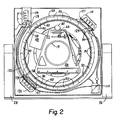
- an x-ray tube 40 and fixed array 42 of x-radiation detectors are visible (see Figure 2).
- the illustrated array 42 completely encircles the' patient aperture 18.
- the x-ray tube 40 generates an x-ray beam which is shaped by a collimator 44 to provide a generally planar spread beam of radiation that passes through the aperture 18 to opposed detectors in the array 42.
- the x-radiation is attenuated by the patient (or any other objects in the path of the x-radiation) and its intensity is then detected by detectors in the array 42.
- the tube 40 and collimator 44 are both mounted to a CT frame 46 which is rotatably mounted to the scanner 12.
- a motor (not shown) at the rear of the CT apparatus imparts rotation- al motion to the frame 46 which is journalled on stationary portions of the scanner 12 by a bearing (not shown) which surrounds the patient aperture.
- a cooling unit 48 is mounted to the side of the x-ray tube and coupled to the tube to circulate coolant to the tube housing.
- the array 42 of detectors is made up of individual modules 50 which each support a plurality of closely spaced detectors in fixed relation-around the patient aperture 180.
- each module 50 supports sixty detectors 51 so that the, 20 modules comprising the array 42 supports 1200 detectors in a circular array.
- Each of the modules 50 can be easily mounted to or removed from the scanner 12 to facilitate assembly or maintenance of an assembled unit.
- a stationary gantry 52 supports a number of module mounts 54 (see Figure 3), with each module mount 54 defining a series of fingers 56 which extend radially outward from the module mount 54. These fingers define threaded openings 58 into which threaded connectors on the modules 50 are screwed to mount the modules 50 about the patient aperture 18.
- a first module is screwed into place and others modules 50 comprising the detector array are successively mounted to a module mount 54 in coacting relationship with the first module until an entire array of twenty modules has been positioned in place.
- FIG. 2 Components of an air conditioning system for directing cool air to the detectors 51 are seen in Figure 2.
- This air conditioning system comprises a compressor 114, a condensor 116 and two evaporator units 118, 120. Since the detectors in the disclosed fourth generation CT apparatus are all stationary, the cooling system components are also all stationary and in particular are mounted on the four corners of the CT housing between that housing and the detector array 42.
- the air conditioning system utilizes a freon coolant to accomplish a heat exchange between cold freon and the relatively warm ambient air surrounding the CT scanner 12.
- the compressor 114 compresses freon in a gaseous state to an elevated temperature and directs this compressed freon to the condensor 116.
- the compressed freon is allowed to expand and cool.
- Condensor coils inside the condensor unit 116 heat ambient air as it is forced past the condensor coils and exited from the system by a hot air exhaust 117.
- the liquid freon leaves the condensor 116, it passes through a filter 119 which purifies the freon.
- the output from the condensor 116 leads to a tee 121 which divides the freon into separate paths 123, 125 to the two evaporator units 118, 120.
- the liquid freon evaporates, and as it does so cools air which is blown from the back of the computed tomography unit through the condensor units 118, 120 to a pair of outlets 127, 129 on each of the evaporator units.
- the cool air is forced through each of the modules 50 to reduce the temperature of the detectors to a point below ambient. This reduction in temperature reduces the noise of the detector outputs.
- Each detector comprises a scintillation crystal coupled to a photodiode which in turn is mounted to a ceramic mounting block.
- the detector is encapsulated in an aluminum can which reflects visible light while allowing x-radiation to be freely transmitted to the scintillation crystal.
- the x-radiation from the x-ray tube impinges upon the scintillation crystal which converts the x-radiation to visible light which in turn affects the current flow in the photodiode. Changes in current produced by the x-radiation are converted from an analog current signal into a sequence of pulses which are counted.
- the steps of detecting the radiation 150 and generating the pulses 151 as well as determining the intensity 152 are depicted in a flow chart ( Figure 4) schematically describing the computed tomography process. These three steps 150, 151, 152 are followed by a logging of the data and a storing 154 of that data in the computer.
- the x-ray intensity measured by a detector is inversely proportional to the exponential of the line integral of the density of the subject for a given radiation path.
- The'logarithm of the intensity data yields density data rather than attenuation information.
- the remaining steps in the computed tomography process are performed by the computer 16.
- the computer first performs a series of calibration and correction - calculations 156 on the data. These calculations are based upon data obtained during a CT set-up phase. These calculations take into account variations in detector sensitivity, gain, and offsets in the electronics.
- a digital filtering step 158 is performed where all data from each detector is filtered in accordance with one of a number of techniques known in the art. Two known techniques employ convolution or fast fourier transforming (FFT) of data. In the later case the process consists of performing a forward FFT of the data, multiplying the transformed data by a spacial frequency filter 160 and then performing an inverse FFT 162 to produce the filtered data.
- FFT fast fourier transforming
- filtered data for those detectors which are not functioning is assigned 164 based upon the filtered data from those detectors which are supplying valid data.
- all data, both from those detectors that are functioning and those which are not, are backprojected 166 into a memory to produce an image of a particular patient slice under examination. Once this backprojection process has been completed, this data is again stored and utilized in imaging 168 a picture of this slice on the console 14.
- the x-ray source 40 rotates about the.patient aperture, it successively irradiates each detector comprising the detector array 42.
- a portion of that array 42 is shown schematically in Figure 5.
- the fan of x-radiation irradiates a portion of the total detectors comprising the array 42.
- the Figure 5 representation shows substantially fewer detectors than when are normally irradiated.
- Shown in Figure 6 is a plot of the data stored in the computer for a given detector as that detector senses radiation from the source 40 in its orbital path about the cross-section subject shown in Figure 5.
- the source 40 rotates about the subject initially, no attenuation in radiation occurs and the corresponding data values for a particular detector will be a minimum.
- the attenuation will be less as the radiation passes through a smaller cross-section until the radiation again passes unattenuated from the source 40 to the detector of interest.
- each detector view comprises 1,024 data values, each of which must be digitally filtered, and then backprojected across a grid or mapping of the cross-section of interest.
- the numbers listed in table 1 comprises a limited number of typical data values that have been filtered from eight adjacent'detectors comprising the array 42. Since a particular view for a detector comprises 1,024 of these points, it is appreciated that only a very limited portion of the view is shown in table 1.
- Various techniques are known for determining which detectors have malfunctioned.
- One procedure is to take a calibration scan and view the backprojected results of that scan. Streaks or artifacts pointing radially away from a single point at the edge of the picture are a strong indication that a detector (or its associated circuitry) has malfunctioned. This suspicion can be confirmed by testing the detector output directly.
- Another technique is to display the data from a sequence of detectors on the console and look for variations which should not exist. This is possible, for example, when the scanner is running a test scan on air or water and there should be only small variations in the detector output around the array 42.
- the missing data values for the non-functioning detector was obtained by summing the data points-from the two detectors on either side of the malfunctioning detector and dividing by two.
- detector #4 would be assigned values corresponding to the average of numbers directly above and below, thus a value of 155 would be assigned to the 5th data point displayed in table 1. This is to be contrasted with the actual data point of 209 which ideally should be assigned for this data point.
- Gross miscalcuclations of the data values for non-functioning detectors caused streaks or artifacts in prior art imaging techniques.
- D(M,N) will be used to mean the value for the R data point of the Mth detector, in table 1.
- D(4,5) has a value of 209 in that table. If the value of D(4,5) is an average of D(3,5) and D(5,5) one obtains 155 for that sample rather than the actual value of 209.
- gradients are computed in a number of directions about a particular data point to be approximated.
- the information contained in these gradient values can be used to determine which data points from near-by good detectors should be used to obtain a more accurage estimate of the missing bad detector data point.
- the single bad detector gradient calculation can be extrapolated to a multiple bad detector approximation. Again, assume that the Mth detector is bad and in this case that L is the nearest lower numbered good detector and H is the nearest higher numbered good detector. If: then where If: then where If: and
- interpolation e.g. linear
- G(M,N) is evaluated for each integer value of u where -U ⁇ u ⁇ U.
- interpolation can be used to determine the value of point ( N + u l + k)
Landscapes
- Health & Medical Sciences (AREA)
- Life Sciences & Earth Sciences (AREA)
- Engineering & Computer Science (AREA)
- Medical Informatics (AREA)
- Radiology & Medical Imaging (AREA)
- Biomedical Technology (AREA)
- Biophysics (AREA)
- High Energy & Nuclear Physics (AREA)
- Veterinary Medicine (AREA)
- Nuclear Medicine, Radiotherapy & Molecular Imaging (AREA)
- Optics & Photonics (AREA)
- Pathology (AREA)
- Public Health (AREA)
- Physics & Mathematics (AREA)
- Heart & Thoracic Surgery (AREA)
- Molecular Biology (AREA)
- Surgery (AREA)
- Animal Behavior & Ethology (AREA)
- General Health & Medical Sciences (AREA)
- Pulmonology (AREA)
- Theoretical Computer Science (AREA)
- Apparatus For Radiation Diagnosis (AREA)
- Analysing Materials By The Use Of Radiation (AREA)
- Closed-Circuit Television Systems (AREA)
Applications Claiming Priority (2)
| Application Number | Priority Date | Filing Date | Title |
|---|---|---|---|
| US44185782A | 1982-11-15 | 1982-11-15 | |
| US441857 | 1989-11-27 |
Publications (2)
| Publication Number | Publication Date |
|---|---|
| EP0109205A2 true EP0109205A2 (fr) | 1984-05-23 |
| EP0109205A3 EP0109205A3 (fr) | 1985-07-31 |
Family
ID=23754575
Family Applications (1)
| Application Number | Title | Priority Date | Filing Date |
|---|---|---|---|
| EP83306359A Withdrawn EP0109205A3 (fr) | 1982-11-15 | 1983-10-19 | Procédé et appareil d'imagerie de tomogrammes traités par ordinateur |
Country Status (2)
| Country | Link |
|---|---|
| EP (1) | EP0109205A3 (fr) |
| JP (1) | JPS59103651A (fr) |
Cited By (7)
| Publication number | Priority date | Publication date | Assignee | Title |
|---|---|---|---|---|
| US4788704A (en) * | 1985-03-04 | 1988-11-29 | Heimann Gmbh | X-ray scanner & detector signal processing system |
| EP0404118A2 (fr) * | 1989-06-21 | 1990-12-27 | Kabushiki Kaisha Toshiba | Appareil de balayage pour la tomographie à rayons X |
| EP0819406A1 (fr) * | 1996-06-20 | 1998-01-21 | Siemens Aktiengesellschaft | Appareil de tomographie |
| EP0982659A2 (fr) * | 1998-08-25 | 2000-03-01 | General Electric Company | Procédé et appareil pour le dépannage d'un système d'imagerie multicoupe évolutif |
| WO2001027877A1 (fr) | 1999-10-14 | 2001-04-19 | Centrum für Dentale Innovationen GmbH | Procede et dispositif tomographiques |
| DE10016372A1 (de) * | 1999-10-14 | 2001-05-31 | Ct Fuer Dentale Innovationen G | Schichtbildverfahren und Schichtbildgerät |
| WO2003024332A2 (fr) * | 2001-09-03 | 2003-03-27 | Siemens Aktiengesellschaft | Procede et dispositif medical conçu pour mettre en oeuvre ce procede |
Families Citing this family (1)
| Publication number | Priority date | Publication date | Assignee | Title |
|---|---|---|---|---|
| US6327329B1 (en) * | 1998-08-25 | 2001-12-04 | General Electric Company | Methods and apparatus for monitoring detector image quality |
Citations (4)
| Publication number | Priority date | Publication date | Assignee | Title |
|---|---|---|---|---|
| FR2260252A1 (fr) * | 1974-01-31 | 1975-08-29 | Emi Ltd | |
| FR2356160A1 (fr) * | 1976-06-22 | 1978-01-20 | Philips Nv | Dispositif pour mesurer le degre d'absorption dans un plan d'un corps |
| GB2005514A (en) * | 1977-09-30 | 1979-04-19 | Ohio Nuclear | Method of and apparatus for examining objects by the use of radiation |
| EP0037151A2 (fr) * | 1980-04-01 | 1981-10-07 | Philips Patentverwaltung GmbH | Appareil de tomographie assisté d'un ordinateur |
-
1983
- 1983-10-19 EP EP83306359A patent/EP0109205A3/fr not_active Withdrawn
- 1983-11-15 JP JP58214919A patent/JPS59103651A/ja active Pending
Patent Citations (4)
| Publication number | Priority date | Publication date | Assignee | Title |
|---|---|---|---|---|
| FR2260252A1 (fr) * | 1974-01-31 | 1975-08-29 | Emi Ltd | |
| FR2356160A1 (fr) * | 1976-06-22 | 1978-01-20 | Philips Nv | Dispositif pour mesurer le degre d'absorption dans un plan d'un corps |
| GB2005514A (en) * | 1977-09-30 | 1979-04-19 | Ohio Nuclear | Method of and apparatus for examining objects by the use of radiation |
| EP0037151A2 (fr) * | 1980-04-01 | 1981-10-07 | Philips Patentverwaltung GmbH | Appareil de tomographie assisté d'un ordinateur |
Cited By (14)
| Publication number | Priority date | Publication date | Assignee | Title |
|---|---|---|---|---|
| US4788704A (en) * | 1985-03-04 | 1988-11-29 | Heimann Gmbh | X-ray scanner & detector signal processing system |
| EP0404118A2 (fr) * | 1989-06-21 | 1990-12-27 | Kabushiki Kaisha Toshiba | Appareil de balayage pour la tomographie à rayons X |
| EP0404118A3 (fr) * | 1989-06-21 | 1991-01-16 | Kabushiki Kaisha Toshiba | Appareil de balayage pour la tomographie à rayons X |
| US5025463A (en) * | 1989-06-21 | 1991-06-18 | Kabushiki Kaisha Toshiba | X-ray CT scanner device |
| EP0819406A1 (fr) * | 1996-06-20 | 1998-01-21 | Siemens Aktiengesellschaft | Appareil de tomographie |
| EP0982659A3 (fr) * | 1998-08-25 | 2005-09-21 | General Electric Company | Procédé et appareil pour le dépannage d'un système d'imagerie multicoupe évolutif |
| EP0982659A2 (fr) * | 1998-08-25 | 2000-03-01 | General Electric Company | Procédé et appareil pour le dépannage d'un système d'imagerie multicoupe évolutif |
| WO2001027877A1 (fr) | 1999-10-14 | 2001-04-19 | Centrum für Dentale Innovationen GmbH | Procede et dispositif tomographiques |
| DE10016372B4 (de) * | 1999-10-14 | 2004-04-29 | Centrum für Dentale Innovationen GmbH | Schichtbildverfahren und Schichtbildgerät |
| DE10016372A1 (de) * | 1999-10-14 | 2001-05-31 | Ct Fuer Dentale Innovationen G | Schichtbildverfahren und Schichtbildgerät |
| WO2003024332A2 (fr) * | 2001-09-03 | 2003-03-27 | Siemens Aktiengesellschaft | Procede et dispositif medical conçu pour mettre en oeuvre ce procede |
| WO2003024332A3 (fr) * | 2001-09-03 | 2003-07-10 | Siemens Ag | Procede et dispositif medical conçu pour mettre en oeuvre ce procede |
| US7109490B2 (en) | 2001-09-03 | 2006-09-19 | Siemens Aktiengesellschaft | Method and medical device designed for implementing this method |
| CN1311788C (zh) * | 2001-09-03 | 2007-04-25 | 西门子公司 | 在多信道光束探测器中恢复故障信道的方法 |
Also Published As
| Publication number | Publication date |
|---|---|
| JPS59103651A (ja) | 1984-06-15 |
| EP0109205A3 (fr) | 1985-07-31 |
Similar Documents
| Publication | Publication Date | Title |
|---|---|---|
| US5307264A (en) | Method and apparatus for computing tomographic scans | |
| US5293312A (en) | Method and apparatus for computing tomographic scans | |
| US6373920B1 (en) | Method and apparatus for acquiring CT perfusion images | |
| JP5047960B2 (ja) | 高度に限定されたイメージの再構成法 | |
| JP4152649B2 (ja) | Ctスカウト画像処理のための方法及び装置 | |
| US7082180B2 (en) | Methods and apparatus for computing volumetric perfusion | |
| US7054475B2 (en) | Apparatus and method for volumetric reconstruction of a cyclically moving object | |
| US4736396A (en) | Tomosynthesis using high speed CT scanning system | |
| US20040125908A1 (en) | Method and apparatus for deriving motion information from projection data | |
| JP3426279B2 (ja) | 計算機式断層写真装置で像を発生する方法 | |
| JPH07246200A (ja) | X線ctスキャナー | |
| JPH08509408A (ja) | 円すい状ビームデータからの画像の再構成 | |
| EP1959835A2 (fr) | Systemes et procedes pour balayage et acquisition de donnees dans des applications de tomographie informatisee (ct) | |
| US4712178A (en) | Malfunctioning computed tomography detector correction method | |
| US6418184B1 (en) | Helical rowwise view weighting of computed tomographic images | |
| US4674045A (en) | Filter for data processing | |
| EP0109205A2 (fr) | Procédé et appareil d'imagerie de tomogrammes traités par ordinateur | |
| US7813473B2 (en) | Method and apparatus for generating temporally interpolated projections | |
| EP0109206A2 (fr) | Procédé et appareil de tomographie à calculatrice | |
| US7379525B2 (en) | Method and system for efficient helical cone-beam reconstruction | |
| EP0608237B1 (fr) | Methode et appareil de calcul de balayages tomographiques et panoramiques | |
| JP3789728B2 (ja) | プロジェクションデータ補正方法および装置並びに放射線断層撮像装置 | |
| EP1103221B1 (fr) | Procédé et appareil pour optimiser la qualité d'image de tomographie à ordinateur avec d'acquisition de données optimisée | |
| US7774040B1 (en) | Method and apparatus of multi-phase cardiac imaging | |
| JP3463002B2 (ja) | 放射線断層撮影装置 |
Legal Events
| Date | Code | Title | Description |
|---|---|---|---|
| PUAI | Public reference made under article 153(3) epc to a published international application that has entered the european phase |
Free format text: ORIGINAL CODE: 0009012 |
|
| AK | Designated contracting states |
Designated state(s): DE FR GB NL |
|
| PUAL | Search report despatched |
Free format text: ORIGINAL CODE: 0009013 |
|
| AK | Designated contracting states |
Designated state(s): DE FR GB NL |
|
| STAA | Information on the status of an ep patent application or granted ep patent |
Free format text: STATUS: THE APPLICATION IS DEEMED TO BE WITHDRAWN |
|
| 18D | Application deemed to be withdrawn |
Effective date: 19860401 |
|
| RIN1 | Information on inventor provided before grant (corrected) |
Inventor name: KENUE, SURENDER K. Inventor name: DEMEESTER, GORDON D. Inventor name: BRUNNETT, CARL J. |