EP0108327A2 - Two-wheeled vehicle, in particular a bicycle - Google Patents
Two-wheeled vehicle, in particular a bicycle Download PDFInfo
- Publication number
- EP0108327A2 EP0108327A2 EP83110622A EP83110622A EP0108327A2 EP 0108327 A2 EP0108327 A2 EP 0108327A2 EP 83110622 A EP83110622 A EP 83110622A EP 83110622 A EP83110622 A EP 83110622A EP 0108327 A2 EP0108327 A2 EP 0108327A2
- Authority
- EP
- European Patent Office
- Prior art keywords
- wheeled vehicle
- vehicle according
- rocker
- spring device
- spring
- Prior art date
- Legal status (The legal status is an assumption and is not a legal conclusion. Google has not performed a legal analysis and makes no representation as to the accuracy of the status listed.)
- Granted
Links
Images


Classifications
-
- B—PERFORMING OPERATIONS; TRANSPORTING
- B62—LAND VEHICLES FOR TRAVELLING OTHERWISE THAN ON RAILS
- B62K—CYCLES; CYCLE FRAMES; CYCLE STEERING DEVICES; RIDER-OPERATED TERMINAL CONTROLS SPECIALLY ADAPTED FOR CYCLES; CYCLE AXLE SUSPENSIONS; CYCLE SIDE-CARS, FORECARS, OR THE LIKE
- B62K3/00—Bicycles
- B62K3/02—Frames
-
- B—PERFORMING OPERATIONS; TRANSPORTING
- B62—LAND VEHICLES FOR TRAVELLING OTHERWISE THAN ON RAILS
- B62J—CYCLE SADDLES OR SEATS; AUXILIARY DEVICES OR ACCESSORIES SPECIALLY ADAPTED TO CYCLES AND NOT OTHERWISE PROVIDED FOR, e.g. ARTICLE CARRIERS OR CYCLE PROTECTORS
- B62J1/00—Saddles or other seats for cycles; Arrangement thereof; Component parts
- B62J1/02—Saddles resiliently mounted on the frame; Equipment therefor, e.g. springs
- B62J1/04—Saddles capable of swinging about a horizontal pivot
-
- B—PERFORMING OPERATIONS; TRANSPORTING
- B62—LAND VEHICLES FOR TRAVELLING OTHERWISE THAN ON RAILS
- B62K—CYCLES; CYCLE FRAMES; CYCLE STEERING DEVICES; RIDER-OPERATED TERMINAL CONTROLS SPECIALLY ADAPTED FOR CYCLES; CYCLE AXLE SUSPENSIONS; CYCLE SIDE-CARS, FORECARS, OR THE LIKE
- B62K21/00—Steering devices
- B62K21/12—Handlebars; Handlebar stems
- B62K21/14—Handlebars; Handlebar stems having resilient parts therein
Definitions
- the invention relates to a two-wheeled vehicle, in particular a bicycle of a generally conventional type, i.e. essentially consisting of a frame with a rotatably mounted front fork and front wheel and handlebar, with a fixed rear fork with rear wheel, saddle with seat post and with a drive unit, for example consisting of a pedal crank mounted in the bottom bracket and a drive on the rear wheel via chain sprocket and chain, if necessary, with a gear shift, brakes and lighting system.
- a bicycle of a generally conventional type i.e. essentially consisting of a frame with a rotatably mounted front fork and front wheel and handlebar, with a fixed rear fork with rear wheel, saddle with seat post and with a drive unit, for example consisting of a pedal crank mounted in the bottom bracket and a drive on the rear wheel via chain sprocket and chain, if necessary, with a gear shift, brakes and lighting system.
- the object of the invention is to provide a novel suspension system for bicycles, with the help of which the hard, health-damaging vibrations caused by bumps in the roadway can be sustainably absorbed, so that they are hardly perceived as disturbing.
- the frame is a Lowered cross strut, that further a rocker carrying the saddle with a seat post is connected to the front, rising part of the frame by a swing joint, and that at least a part of the rear frame part contains a spring device.
- a particularly advantageous embodiment of the invention consists in that the upper cross strut is inclined from front to back, that the rocker arm has a U-shaped cross section, the side cheeks of which are wider from front to back in accordance with the inclination of the cross strut and cover them so that the Sidewalls front and rear have tabs with bearing bushes for receiving articulated axles, so that the rocker is articulated on the one hand with the fork head and on the other hand with the spring device, and that the spring device is arranged approximately parallel to the rear, rising part of the frame between the bottom bracket housing and the swing arm is.
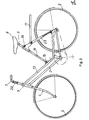
- This bicycle 1 shows a bicycle of the type described in the beginning, constructed in its essential parts in the usual way.
- This bicycle 1 has a frame 2, wheels 3, a front wheel fork 4 which is rotatably mounted in the fork head 5, a rear wheel fork 6, a handlebar 7, a saddle 8 with a seat post 9, pedal cranks 10 mounted in the bottom bracket for a chain drive on the rear wheel, a luggage rack 11 and brakes 12.
- a lighting system is also indicated.
- the cross strut 13 which is normally located between the fork head and the part of the frame which carries the saddle with seat post is lower and is welded to the front, upwardly rising frame part.
- the lowered frame part 13 preferably widens in its rear part to form a fork 14 which continues into the rear wheel fork 6.
- a swivel joint 15 is now provided on the fork head 5, in which a swing arm 16 is pivotally mounted, and which is purely external takes the place of the former cross strut.
- This rocker is welded to a sleeve receiving the seat post 9, on which in turn at least one spring device 17, preferably a spring strut or a telescopic spring is attached, the other end of which is attached to a frame part which is welded to a sleeve on the bottom bracket.
- two juxtaposed spring devices can also be used.
- the cross strut 13 had to pass through between the two struts or telescopic springs and only then widen to the fork 14 or rear wheel fork 6.
- a height adjustment device 18 for the saddle 8 is provided on the sleeve receiving the saddle support 9.
- a height adjustment device 19 for the telescopic spring or the strut is provided at the upper end of the frame part extending from the bottom bracket.
- a curved handlebar 7 is attached to a handlebar stem 20 and is rotatably supported there in a horizontal axis. Between the curved handlebar 7 and the handlebar stem 20 two compression springs 21 are then provided, through which the handlebar 7 is cushioned so that the lugs transmitted from the front wheel can not be transferred to the arms of the cyclist.
- the spring bumps 17 softly cushion the roadway impacts originating from the roadway and transmitted in the direction of the saddle.
- this spring device ie the strut or the telescopic spring is preferred its spring force can be adjusted to the respective weight of the cyclist.
- Fig. 2 shows a women's bicycle constructed according to the same principle, the same parts again being provided with the same reference numerals. It can be seen that the lowered cross strut is now set much lower, and is welded there to the front rising frame part. Here too, depending on whether one or two spring devices 17 are to be used, the lowered cross strut 13 can expand into the fork 14 before or after the respective spring arrangement.
- the swing arm 16 is also angled downward in the manner customary for women's bicycles, but otherwise fulfills the same function as the swing arm 16 in FIG. 1.
- a straight link 7 can also be seen, which is now cushioned by a telescopic spring 22 arranged between the link and fork head 5.
- a telescopic spring 22 arranged between the link and fork head 5.
- a further embodiment of a women's bicycle is shown, which is constructed similarly to the embodiment according to Fig. 2, but with the difference that the swing joint 15 is now welded or arranged near the lower end of the lower cross strut 13, and that Swing arm 16 now ends in a sleeve, which also carries the saddle 8 with seat post 9, the height of which is adjustable by the height adjustment device 18.
- This sleeve is now available an approach an axis on which two struts 23 are arranged, which replace the rear fork here.
- a Telskopfeder is also installed in the rocker 16. Furthermore, it is also conceivable in the embodiments according to FIGS. 1 and 2 to install telescopic springs 23 in the rear wheel fork 6.
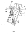
- FIG. 4 shows a frame 31 with a fork head 32, on which the attachment of the fork and the attachment of the handlebar are indicated. Furthermore, one recognizes a front, rising frame part 33, a rear, rising frame part 34 and a cross strut 35 falling from front to back, which is welded or screwed and brazed to the fork head 32 on the one hand and to the rear rising frame part on the other hand.
- a bottom bracket housing 36 is connected to the front frame part 33.
- the rear fork 42 is on the one hand with the bottom bracket 36 and also firmly connected to the cross strut 35 in a manner to be specified.
- a rocker 37 with a U-shaped cross section is pivotally attached to a rocker joint 38 via tabs 39, which are made in one piece with the rocker 37, and a thru-axle, not shown, on a bushing, likewise not shown here.
- the side cheeks of the rocker 37 become ever wider from the front to the rear and end at the end in mounting brackets 40 which extend far downward and which are also provided with bushings which, by means of an axis or a pin, serve to fasten a spring device 41 which, for example, is a commercially available one hydraulic strut could be.
- the lower end of this spring device 41 is fastened to two bearing blocks, which in turn are firmly connected to the bottom bracket housing 36 and preferably also to the rear rising frame part 34.
- the upward struts of the rear wheel fork 42 are angled at their upper end in an approximately vertical direction, firmly connected to the cross strut 35 and carry a preferably detachably fastened guide rail 44 which is able to slide between the open end of the rocker 37 cut out at this point.
- seat post tubes 45 are attached, which carry clamping screws 46 at their upper ends, with the help of which the seat post 47 inserted into the seat post tubes, which carry a saddle 48, can be set in an adjustable height.
- the rocker 37 can in principle be made of any suitable, sufficiently torsion-resistant material. For weight reasons one could use plastics, especially glass fiber reinforced plastics prefer instead of aluminum or steel. When plastics are used, a reinforcement part 49, which is also U-shaped and pulled far down, should then be provided in the area of the seat posts.
- This new construction of the swingarm opens up a whole range of construction options for women's bicycles or children's bicycles.
- the saddle can be attached directly to the swingarm itself without a seatpost.
- the upper cross strut and the rocker can be pulled far down.
- FIG. 6 A further embodiment of the invention is shown schematically in FIG. 6, the same parts again being provided with the same reference numerals.
- a leaf spring 50 is indicated purely schematically within the rocker arm, which can be angled either on one side or, as shown, on two sides and provides an additional strong preload for the rocker arm.
- Also shown schematically is an adjusting device 51 with which the spring preload can be changed to a limited extent. This has the great advantage that one can divide the spring force between leaf spring 50 and spring device Al. This allows weight savings to be achieved with the spring device with a smaller model.
- the resulting stroke on this rocker is approximately between 30 and 50 mm.
- the radius of the rocker is approximately 500 to 600 mm.
- the construction is much more stable on the side and ensures much better guidance of the rocker during operation.
- the undesirable scissor effect is eliminated.
- the invention is for the ever-expanding rides on narrow trails, dirt roads and. the like. Of importance, which can not be driven on in the long run with their bumps with a commercially available bicycle without causing damage to the spine of the user of the bicycle.
- the present invention is therefore very well suited to further promoting hiking with bicycles, also via secondary paths, forest paths and dirt roads, and its importance for health can hardly be overestimated.
Abstract
Description
Die Erfindung betrifft ein Zweiradfahrzeug, insbesondere Fahrrad mit im allgemeinen üblicher Bauart, d.h. im wesentlichen bestehend aus einem Rahmen mit drehbar gebgerter Vorderradgabel und Vorderrad sowie Lenker, mit feststehender Hinterradgabel mit Hinterrad, Sattel mit Sattelstütze und mit einem Antriebsaggregat, beispielsweise bestehend aus im Tretlager gelagerten Tretkurbein und einem über Kettenzahnrader und Kette erfolgenden Antrieb auf das Hinterrad, ggf, mit einer Gangschaltung, Bremsen und Beleuchtungsanlage.The invention relates to a two-wheeled vehicle, in particular a bicycle of a generally conventional type, i.e. essentially consisting of a frame with a rotatably mounted front fork and front wheel and handlebar, with a fixed rear fork with rear wheel, saddle with seat post and with a drive unit, for example consisting of a pedal crank mounted in the bottom bracket and a drive on the rear wheel via chain sprocket and chain, if necessary, with a gear shift, brakes and lighting system.
Bei bisher bekannten Fahrrädern hing der Fahrkomfort meist von der mehr oder weniger unvollkommen wirksamen Federung des Sattels ab. Die heute meist verwendeten schmalen Hochdruckreifen übertragen die Unebenheiten der Straßen und Wege fast ungefedert auf den Rahmen und damit auf den Radfahrer. Die früher einmal gebräuchlichen Ballonbereifung war in dieser Hinsicht nicht viel besser. Es sind auch schon Versuche unternommen worden, insbesondere das Hinterrad an zwei Schwinghebeln, die an der Hinterradgabel federnd angelenkt sind, anzubringen. Dabei lassen sich jedoch nur sehr kleine Federwege erzielen.In previously known bicycles, the ride comfort mostly depended on the more or less imperfectly effective suspension of the saddle. The narrow high-pressure tires most commonly used today transmit the bumps of the roads and paths almost unsprung to the frame and thus to the cyclist. The balloon tires used in the past were not much better in this regard. Attempts have also already been made to attach the rear wheel in particular to two rocker arms which are resiliently articulated on the rear wheel fork. However, only very small spring travel can be achieved.
Aufgabe der Erfindung ist es, ein neuartiges Federungssystem für Fahrräder anzugeben, mit dessen Hilfe die harten gesundheitsschädlichen, durch Unebenheiten der Fahrbahn verursachten Erschütterungen nachhaltig abgefedert werden können, so daß diese kaum noch als störend empfunden werden.The object of the invention is to provide a novel suspension system for bicycles, with the help of which the hard, health-damaging vibrations caused by bumps in the roadway can be sustainably absorbed, so that they are hardly perceived as disturbing.
Dies wird erfindungsgemäß dadurch erreicht, daß der Rahmen eine tiefergelegte Querstrebe aufweist, daß ferner eine den Sattel mit SattelstUtze tragende Schwinge mit dem vorderen, ansteigenden Teil des Rahmens durch ein Schwinggelenk verbunden ist, und daß mindestens ein Teil des rückwärtigen Rahmenteil eine Federvorrichtung enthölt.This is achieved according to the invention in that the frame is a Lowered cross strut, that further a rocker carrying the saddle with a seat post is connected to the front, rising part of the frame by a swing joint, and that at least a part of the rear frame part contains a spring device.
Eine besonders vorteilhafte Ausgestaltung der Erfindung besteht darin, daß die obere Querstrebe von vorne nach hinten abfallend geneigt ist, daß die Schwinge einen U-förmigen Querschnitt aufweist, dessen Seitenwangen von vorne nach hinten entsprechend der Neigung der Querstrebe breiter werden und diese verdecken, daßdabei die Seitenwangen vorne und hinten Laschen mit Lagerbuchsen zur Aufnahme von Gelenkachsen aufweisen, daß damit die Schwinge einerseits mit dem Gabelkopf und andererseits mit der Federvorrichtung gelenkig verbunden ist, und daß die Federvorrichtung etwa parallel zum hinteren, ansteigenden Teil des Rahmens zwischen dem Tretlagergehäuse und der Schwinge angeordnet ist.A particularly advantageous embodiment of the invention consists in that the upper cross strut is inclined from front to back, that the rocker arm has a U-shaped cross section, the side cheeks of which are wider from front to back in accordance with the inclination of the cross strut and cover them so that the Sidewalls front and rear have tabs with bearing bushes for receiving articulated axles, so that the rocker is articulated on the one hand with the fork head and on the other hand with the spring device, and that the spring device is arranged approximately parallel to the rear, rising part of the frame between the bottom bracket housing and the swing arm is.
Weitere Ausgestaltungen der Erfindung sind den weiteren Ansprüchen zu entnehmen.Further refinements of the invention can be found in the further claims.
Die Erfindung wird nunmehr anhand von Ausführungsbeispielen in Verbindung mit den beigefügten Zeichnungen naher beschrieben.The invention will now be described in more detail by means of embodiments in conjunction with the accompanying drawings.
In den Zeichnungen zeigt:
- Fig. 1 ein Herrenfahrrad mit Federung gemäß der Erfindung;
- Fig. 2 ein Damenfahrrad mit Federung gemäß der Erfindung;
- Fig. 3 eine weitere Ausführungsform eines Damenfahrrades mit Federung gemäß der Erfindung;
- Fig. 4 eine perspektivische Teilansicht der neuen Rahmenkonstruktion;
- Fig. 5 eine schematische Darstellung der beiden Endlagen der Schwinge mit Sattel und
- Fig. 6 schematisch eine weitere AusfUhrungsform der Erfindung.
- 1 shows a men's bicycle with suspension according to the invention.
- Figure 2 shows a women's bicycle with suspension according to the invention.
- 3 shows a further embodiment of a women's bicycle with suspension according to the invention;
- Fig. 4 is a partial perspective view of the new frame construction;
- Fig. 5 is a schematic representation of the two end positions of the rocker with saddle and
- 6 schematically shows a further embodiment of the invention.
Fig. 1 zeigt ein in seinen wesentlichen Teilen in Ublicher Weise aufgebautes Fahrrad der eingangs beschriebenen Art. Dieses Fahrrad 1 weist einen Rahmen 2, Räder 3, eine Vorderradgabel 4, die im Gabelkopf 5 drehbar gelagert ist, eine Hinterradgabel 6, einen Lenker 7, einen Sattel 8 mit Sattelstütze 9, im Tretlager gelagerte Tretkurbeln 10 für einen Kettenantrieb auf das Hinterrad, einen Gepäckträger 11 und Bremsen 12 auf. Eine Beleuchtungsanlage ist ebenfalls angedeutet.1 shows a bicycle of the type described in the beginning, constructed in its essential parts in the usual way. This bicycle 1 has a frame 2,
Man erkennt jedoch, daß die normalerweise zwischen Gabelkopf und dem den Sattel mit Sattelstütze tragenden Teil des Rahmens liegende Querstrebe 13 tiefer gelegt ist und mit dem vorderen, nach oben ansteigenden Rahmenteil verschweißt ist. Das tiefergelegte Rahmenteil 13 erweitert sich vorzugsweise in seinem rückwärtigen Teil zu einer Gabel 14, die sich dan in die Hinterradgabel 6 fortsetzt.However, it can be seen that the
Am Gabelkopf 5 ist nunmehr ein Schwinggelenk 15 vorgesehen, in dem eine Schwinge 16 verschwenkbar gelagert ist, und die rein äußerlich den Platz der früheren Querstrebe einnimmt. Diese Schwinge ist an einer die Sattelstütze 9 aufnehmenden Muffe angeschweißt, an der wiederum mindestens eine Federvorrichtung 17, vorzugsweise ein Federbein oder eine Teleskopfeder befestigt ist, deren anderes Ende an einem Rahmenteil befestigt ist, das an einer Muffe am Tretlager angeschweißt ist. Selbstverstöndlich können auch zwei nebeneinanderliegende Federvorrichtungen verwendet werden. In diesem Fall mußte die Querstrebe 13 zwischen den beiden Federbeinen oder Teleskopfedern hindurchreichen und sich erst dann zur Gabel 14 bzw. Hinterradgabel 6 erweitern.A
An der die SattelstUtze 9 aufnehmenden Muffe ist eine Höhenverstellvorrichtung 18 für den Sattel 8 vorgesehen. In gleicher Weise ist an dem oberen Ende des vom Tretlager ausgehenden Rahmenteils eine Höhenverstellvorrichtung 19 für die Teleskopfeder oder das Federbein vorgesehen.A
Außerdem erkennt man, daß ein geschwungener Lenker 7 an einem Lenkervorbau 20 angebracht ist und dort in einer waagerechten Achse um diese drehbar gelagert ist. Zwischen dem geschwungenen Lenker 7 und dem Lenkervorbau 20 sind dann zwei Druckfedern 21 vorgesehen, durch die der Lenker 7 so abgefedert ist, daß die vom Vorderrad übertragenen Fahrbahnanstöße sich nicht auf die Arme des Radfahrers übertragen können.In addition, it can be seen that a
Im Betrieb werden durch die Federvorrichtung 17 die von der Fahrbahn herrührenden, in Richtung auf den Sattel Übertragenen Fahrbahnstöße weich abgefedert. Es ist dabei darauf hinzuweisen, daß diese Federvorrichtung, d.h. das Federbein oder die Teleskopfeder vorzugsweise in ihrer Federkraft auf das jeweilige Gewicht des Radfahrers einstellbar ist.In operation, the
Fig. 2 zeigt ein nach dem gleichen Prinzip aufgebautes Damenfahrrad, wobei gleiche Teile wiederum mit den gleichen Bezugszeichen versehen sind. Man erkennt, daß die tiefergelegte Querstrebe nunmehr wesentlich tiefer angesetzt ist, und dort mit dem vorderen ansteigenden Rahmenteil verschweißt ist. Auch hier kann die tiefergelegte Querstrebe 13 je nachdem, ob eine oder zwei Federvorrichtungen 17 verwendet werden sollen, vor oder nach der jeweiligen Federanordnung sich zur Gabel 14 erweitern.Fig. 2 shows a women's bicycle constructed according to the same principle, the same parts again being provided with the same reference numerals. It can be seen that the lowered cross strut is now set much lower, and is welded there to the front rising frame part. Here too, depending on whether one or two
Da es sich hier um ein Damenfahrrad handelt, ist die Schwinge 16 ebenfalls in der für Damenfahrräder üblichen Weise nach unten abgewinkelt, erfüllt aber im übrigen die gleiche Funktion wie die Schwinge 16 in Fig. 1.Since this is a women's bicycle, the
Man erkennt ferner einen geraden Lenker 7, der nunmehr durch eine zwischen Lenker und Gabelkopf 5 angeordnete Teleskopfeder 22 abgefedert ist. Vorzugsweise wird man dabei eine Querstrebe vorsehen und zwischen dieser Querstrebe und dem geraden Lenker 7 zwei Teleskopfedern 22 oder eine Doppel-Teleskopfeder vorsehen.A
In Fig. 3 ist eine weitere AusfUhrungsform eines Damenfahrrades gezeigt, die ähnlich aufgebaut ist wie das AusfUhrungsbeispiel gemäß Fig. 2, jedoch mit dem Unterschied, daß das Schwinggelenk 15 nunmehr nahe dem unteren Ende der tiefergelegten Querstrebe 13 angeschweißt oder angeordnet ist, und daß die Schwinge 16 nunmehr in einer Muffe endet, die auch den Sattel 8 mit Sattelstütze 9 trägt, dessen Höhenlage durch die Höhenverstellvorrichtung 18 einstellbar ist. Diese Muffe tragt nun an einem Ansatz eine Achse, an der zwei Federbeine 23 angeordnet sind, die hier die Hinterradgabel ersetzen.In Fig. 3 a further embodiment of a women's bicycle is shown, which is constructed similarly to the embodiment according to Fig. 2, but with the difference that the
Ferner ist es bei dieser AusfUhrungsform denkbar, daß in der Schwinge 16 ebenfalls noch eine Telskopfeder eingebaut ist. Des weiteren ist es auch bei den Ausführungsformen nach Fig. 1 und 2 durchaus denkbar, in der Hinterradgabel 6 noch Teleskopfedern 23 einzubauen.Furthermore, it is conceivable in this embodiment that a Telskopfeder is also installed in the
Durch diese neuartige Anordnung von Teleskopfedern und einer um ein Schwinggelenk 15 verschwenkbaren Schwinge 16 erhält man einen relativ langen Federweg und kann somit die Federung sehr genau auf die jeweiligen Bedürfnisse des Radfahrers einstellen.This novel arrangement of telescopic springs and a
Diese Ausführungsform der Erfindung läßt allerdings noch einige Wünsche bezüglich Stabilität und Genauigkeit der Führung der Federvorrichtung offen. Es scheint möglicherweise nachteilig zu sein, daß bei einigen Ausführungsbeispielen sich zwischen Schwinge und der oberen, tiefer gelegten Querstrebe eine Art Scherenwirkung ergibt, da die Schwinge immer oberhalb der tiefer gelegten Querstrebe liegt.However, this embodiment of the invention still leaves some wishes open regarding stability and accuracy of the guidance of the spring device. It may seem to be disadvantageous that in some embodiments there is a kind of scissor action between the rocker and the upper, lower cross strut, since the rocker is always above the lower cross strut.
In Fig. 4 erkennt man einen Rahmen 31 mit einem Gabelkopf 32, an dem der Ansatz der Gabel und der Ansatz der Lenkstange angedeutet sind. Ferner erkennt man ein vorderes, ansteigendes Rahmenteil 33, ein rückwärtiges, ansteigendes Rahmenteil 34 und eine von vorne nach hinten abfallende Querstrebe 35, die einerseits mit dem Gabelkopf 32 und andererseits mit dem rückwärtigen ansteigenden Rahmenteil verschweißt oder vermufft und hartgelötet ist. Außerdem ist mit dem vorderen Rahmenteil 33 ein Tretlagergehäuse 36 verbunden. Des weiteren ist auch die Hinterradgabel 42 einerseits mit dem Tretlager 36 und außerdem in noch anzugebender Weise mit der Querstrebe 35 fest verbunden.4 shows a
Eine Schwinge 37 mit U-förmigem Querschnitt ist an einem Schwinggelenk 38 über mit der Schwinge 37 aus einem StUck gefertigte Laschen 39 und einer nicht gezeigten Steckachse an einer ebenfalls hier nicht zu sehenden Buchse schwenkbar befestigt. Die Seitenwangen der Schwinge 37 werden von vorne nach hinten immer breiter und laufen am Ende in weit nach unten ausgreifende Montagelaschen 40 aus, die ebenfalls mit Buchsen versehen sind, die mittels einer Achse oder eines Zapfens der Befestigung einer Federvorrichtung 41 dienen, die beispielsweise ein handelsübliches hydraulisches Federbein sein könnte. Das untereEnde dieser Federvorrichtung 41 ist an zwei Lagerböcken befestigt, die ihrerseits mit dem Tretlagergehäuse 36 und vorzugsweise auch mit dem hinteren ansteigenden Rahmenteil 34 fest verbunden sind. Die nach oben führenden Streben der Hinterradgabel 42 sind an ihrem oberen Ende in etwa senkrechter Richtung abgewinkelt, fest mit der Querstrebe 35 verbunden und tragen eine vorzugsweise lösbar befestigte Führungsschiene 44, die zwischen dem offenen Ende der an dieser Stelle ausgeschnittenen Schwinge 37 zu gleiten vermag. An der Schwinge selbst sind Sattelstützrohre 45 angebracht, die an ihren oberen Enden Klemmschrauben 46 tragen, mit deren Hilfe die in die Satte lstützrohre eingeführten Sattelstützen 47, die einen Sattel 48 tragen, in ihrer Höhenlage verstellbar festgelegt werden können.A
Die Schwinge 37 kann im Prinzip aus jedem geeigneten, ausreichend verwindungssteifen Material gefertigt sein. Aus Gewichtsgründen könnte man Kunststoffe, insbesondere glasfaserverstärkte Kunststoffe an Stelle von Aluminium oder Stahl bevorzugen. Bei Verwendung von Kunststoffen sollte dann im Bereich der Sattelstützen ein ebenfalls U-förmiges, weit nach unten gezogenes Verstärkungsteil 49 vorgesehen sein.The
Diese neuartige Konstruktion der Schwinge eröffnet eine ganze Reihe von Konstruktionsmöglichkeiten auch für Damenfahrräder oder Kinderfahrräder. So kann beispielsweise der Sattel auch ohne Sattelstütze unmittelbar auf der Schwinge selbst angebracht werden. Ferner können obere Querstrebe und Schwinge weit heruntergezogen sein.This new construction of the swingarm opens up a whole range of construction options for women's bicycles or children's bicycles. For example, the saddle can be attached directly to the swingarm itself without a seatpost. Furthermore, the upper cross strut and the rocker can be pulled far down.
Wie man aus Fig. 5 erkennt, in der gleiche Teile wiederum mit den gleichen Bezugszeichen versehen sind, läßt sich der Sattel mit der Schwinge bei Belastung um eine ganz erhebliche Strecke nach unten verschieben. Entscheidend ist bei dieser Konstruktion, daß durch den langen Hebelarm der Schwinge und die gelenkig gelagerte Federvorrichtung ein so günstiger Radius fUr die Schwingbewegung erreicht wird, daß ein Verklemmen der Federvorrichtung praktisch ausgeschlossen ist.As can be seen from Fig. 5, in which the same parts are again provided with the same reference numerals, the saddle with the rocker can be moved down a very considerable distance under load. It is crucial in this construction that the long lever arm of the rocker and the articulated spring device achieve such a favorable radius for the swinging movement that jamming of the spring device is practically impossible.
In Fig. 6 ist schematisch eine weitere Ausführungsform der Erfindung gezeigt, wobei wiederum gleiche Teile mit den gleichen Bezugszeichen versehen sind. Innerhalb der Schwinge ist rein schematisch eine Blattfeder 50 angedeutet, die entweder einseitig, oder, wie dargestellt, zweiseitig abgewinkelt sein kann und eine zusätzliche kräftige Vorspannung für die Schwinge liefert. Ebenfalls schematisch angedeutet ist eine Verstellvorrichtung 51, mit der die Federvorspannnung begrenzt verändert werden kann. Dies hat den großen Vorzug, daß man die Federkraft zwischen Blattfeder 50 und Federvorrichtung Alaufteilen kann. Damit läßt sich bei der Federvorrichtung mit einem kleineren Modell eine Gewichtseinsparung erzielen.A further embodiment of the invention is shown schematically in FIG. 6, the same parts again being provided with the same reference numerals. A
Der sich bei dieser Schwinge ergebende Hub beträgt etwa zwischen 30 und 50 mm. Der Radius der Schwinge beträgt etwa 500 bis 600 mm. Insgesamt ist die Konstruktion wesentlich seitenstabiler und gewährleistet eine wesentlich bessere Führung der Schwinge im Betrieb. Außerdem ist der unerwünschte Schereneffekt beseitigt.The resulting stroke on this rocker is approximately between 30 and 50 mm. The radius of the rocker is approximately 500 to 600 mm. Overall, the construction is much more stable on the side and ensures much better guidance of the rocker during operation. In addition, the undesirable scissor effect is eliminated.
Zur Gewichtseinsparung könnte man außerdem noch die Schenkel oder Seitenwangen der Schwinge mit einer oder mehreren Öffnungen versehen.To save weight, one could also provide the legs or side cheeks of the rocker with one or more openings.
Die Erfindung ist für die sich immer weiter ausbreitenden Fahrten auf schmalen Wanderwegen, Feldwegen u. dergl. von Bedeutung, die mit ihren Unebenheiten mit einem handelsüblichen Fahrrad auf die Dauer nicht befahren werden können, ohne beim Benutzer des Fahrrades zu Wirbelsäulenschäden zu führen. Die vorliegende Erfindung ist also ganz hervorragend geeignet, das Wandern mit Fahrrädern auch über Nebenwege, Waldwege und Feldwege weiter zu fördern und kann in seiner Bedeutung für die Gesundheit kaum überschätzt werden.The invention is for the ever-expanding rides on narrow trails, dirt roads and. the like. Of importance, which can not be driven on in the long run with their bumps with a commercially available bicycle without causing damage to the spine of the user of the bicycle. The present invention is therefore very well suited to further promoting hiking with bicycles, also via secondary paths, forest paths and dirt roads, and its importance for health can hardly be overestimated.
Claims (20)
Priority Applications (1)
| Application Number | Priority Date | Filing Date | Title |
|---|---|---|---|
| AT83110622T ATE33802T1 (en) | 1982-11-02 | 1983-10-25 | TWO-WHEELED VEHICLE, ESPECIALLY BICYCLE. |
Applications Claiming Priority (4)
| Application Number | Priority Date | Filing Date | Title |
|---|---|---|---|
| DE19823240398 DE3240398A1 (en) | 1982-11-02 | 1982-11-02 | Two-wheeled vehicle, in particular bicycle |
| DE3240398 | 1982-11-02 | ||
| DE3312040 | 1983-04-02 | ||
| DE19833312040 DE3312040A1 (en) | 1983-04-02 | 1983-04-02 | Two-wheeled vehicle, in particular bicycle |
Publications (3)
| Publication Number | Publication Date |
|---|---|
| EP0108327A2 true EP0108327A2 (en) | 1984-05-16 |
| EP0108327A3 EP0108327A3 (en) | 1984-07-25 |
| EP0108327B1 EP0108327B1 (en) | 1988-04-27 |
Family
ID=25805473
Family Applications (1)
| Application Number | Title | Priority Date | Filing Date |
|---|---|---|---|
| EP83110622A Expired EP0108327B1 (en) | 1982-11-02 | 1983-10-25 | Two-wheeled vehicle, in particular a bicycle |
Country Status (2)
| Country | Link |
|---|---|
| EP (1) | EP0108327B1 (en) |
| DE (1) | DE3376407D1 (en) |
Cited By (12)
| Publication number | Priority date | Publication date | Assignee | Title |
|---|---|---|---|---|
| EP0222733A1 (en) * | 1985-11-11 | 1987-05-20 | Steyr-Daimler-Puch Aktiengesellschaft | Bicycle frame |
| FR2675459A1 (en) * | 1991-04-17 | 1992-10-23 | Guillet Christian | Device for fitting a saddle to a bicycle frame |
| WO1994003357A1 (en) * | 1991-04-17 | 1994-02-17 | Christian Guillet | Device for mounting a saddle on a bicycle frame |
| FR2704826A1 (en) * | 1993-05-06 | 1994-11-10 | Corniglion Louis | Deformable bicycle frame with articulations and suspensions |
| GB2310176A (en) * | 1996-02-14 | 1997-08-20 | Michael Douglas Messenger | Bicycle seat suspension comprises spherical spring |
| EP1113939A1 (en) * | 1999-06-22 | 2001-07-11 | Becker Suspensions, Inc. | Shock absorbing bicycle seat support having variable height adjustment |
| GB2358841A (en) * | 2000-02-04 | 2001-08-08 | Atb Sales Ltd | Bicycle frame |
| FR2808493A1 (en) * | 2000-05-02 | 2001-11-09 | Gerard Lamy | All terrain bicycle has pedal crank movably mounted to frame to accommodate uneven terrain |
| EP1298044A1 (en) * | 2001-09-26 | 2003-04-02 | Stefan Roth | Bicycle |
| EP2052957A3 (en) * | 2007-10-17 | 2010-01-06 | Merida & Centurion Germany GmbH | Bicycle frame |
| EP2639149A1 (en) * | 2012-03-15 | 2013-09-18 | Canyon Bicycles GmbH | Bicycle frame saddle tube |
| US20220177071A1 (en) * | 2019-06-18 | 2022-06-09 | Darrell W. Voss | Vehicle |
Citations (15)
| Publication number | Priority date | Publication date | Assignee | Title |
|---|---|---|---|---|
| DE164930C (en) * | ||||
| BE488779A (en) * | 1900-01-01 | |||
| FR359453A (en) * | 1904-11-15 | 1906-03-28 | Georges Boivin | Frame and suspension system for bicycles, motorcycles, tricycles, tri-cars, etc. |
| FR369857A (en) * | 1906-07-24 | 1907-01-23 | Andre Potdevin | Elastic suspension for motorcycle seats |
| FR474361A (en) * | 1914-06-30 | 1915-02-18 | Dussart & Accou Soc | Bicycle with independent suspension of the main frame |
| GB118441A (en) * | 1917-08-27 | 1918-08-27 | Lancelot Steele Parker | Improvements in and relating to the Saddle Supporting Mechanism of Motor Cycles. |
| GB177300A (en) * | 1921-01-15 | 1922-03-30 | John Marr Corner | Improved means for resiliently-supporting the saddle of a motor or other cycle |
| FR617118A (en) * | 1926-06-05 | 1927-02-14 | Elastic support for bicycle saddle | |
| GB391471A (en) * | 1930-10-09 | 1933-04-10 | Abram Neiman | Improvements in or relating to elastic suspensions and vibration dampers for vehicles and cycles |
| DE866312C (en) * | 1951-09-09 | 1953-02-09 | Duerkoppwerke Ag | motorcycle |
| FR1052078A (en) * | 1952-03-05 | 1954-01-21 | Elastic handlebar device for cycles | |
| DE1011305B (en) * | 1951-12-29 | 1957-06-27 | Heinz Mueller | Two-axle vehicle, preferably a bicycle |
| BE670576A (en) * | 1965-01-04 | 1966-01-31 | ||
| US3377084A (en) * | 1966-05-12 | 1968-04-09 | M T & D Company | Seat for velocipede |
| DE2655595A1 (en) * | 1976-01-12 | 1977-07-14 | Kuniyoshi Kanazawa | BICYCLE |
-
1983
- 1983-10-25 EP EP83110622A patent/EP0108327B1/en not_active Expired
- 1983-10-25 DE DE8383110622T patent/DE3376407D1/en not_active Expired
Patent Citations (15)
| Publication number | Priority date | Publication date | Assignee | Title |
|---|---|---|---|---|
| DE164930C (en) * | ||||
| BE488779A (en) * | 1900-01-01 | |||
| FR359453A (en) * | 1904-11-15 | 1906-03-28 | Georges Boivin | Frame and suspension system for bicycles, motorcycles, tricycles, tri-cars, etc. |
| FR369857A (en) * | 1906-07-24 | 1907-01-23 | Andre Potdevin | Elastic suspension for motorcycle seats |
| FR474361A (en) * | 1914-06-30 | 1915-02-18 | Dussart & Accou Soc | Bicycle with independent suspension of the main frame |
| GB118441A (en) * | 1917-08-27 | 1918-08-27 | Lancelot Steele Parker | Improvements in and relating to the Saddle Supporting Mechanism of Motor Cycles. |
| GB177300A (en) * | 1921-01-15 | 1922-03-30 | John Marr Corner | Improved means for resiliently-supporting the saddle of a motor or other cycle |
| FR617118A (en) * | 1926-06-05 | 1927-02-14 | Elastic support for bicycle saddle | |
| GB391471A (en) * | 1930-10-09 | 1933-04-10 | Abram Neiman | Improvements in or relating to elastic suspensions and vibration dampers for vehicles and cycles |
| DE866312C (en) * | 1951-09-09 | 1953-02-09 | Duerkoppwerke Ag | motorcycle |
| DE1011305B (en) * | 1951-12-29 | 1957-06-27 | Heinz Mueller | Two-axle vehicle, preferably a bicycle |
| FR1052078A (en) * | 1952-03-05 | 1954-01-21 | Elastic handlebar device for cycles | |
| BE670576A (en) * | 1965-01-04 | 1966-01-31 | ||
| US3377084A (en) * | 1966-05-12 | 1968-04-09 | M T & D Company | Seat for velocipede |
| DE2655595A1 (en) * | 1976-01-12 | 1977-07-14 | Kuniyoshi Kanazawa | BICYCLE |
Cited By (15)
| Publication number | Priority date | Publication date | Assignee | Title |
|---|---|---|---|---|
| EP0222733A1 (en) * | 1985-11-11 | 1987-05-20 | Steyr-Daimler-Puch Aktiengesellschaft | Bicycle frame |
| FR2675459A1 (en) * | 1991-04-17 | 1992-10-23 | Guillet Christian | Device for fitting a saddle to a bicycle frame |
| WO1994003357A1 (en) * | 1991-04-17 | 1994-02-17 | Christian Guillet | Device for mounting a saddle on a bicycle frame |
| FR2704826A1 (en) * | 1993-05-06 | 1994-11-10 | Corniglion Louis | Deformable bicycle frame with articulations and suspensions |
| GB2310176A (en) * | 1996-02-14 | 1997-08-20 | Michael Douglas Messenger | Bicycle seat suspension comprises spherical spring |
| GB2310176B (en) * | 1996-02-14 | 1999-12-15 | Michael Douglas Messenger | Improvements in or relating to bicycles |
| EP1113939A1 (en) * | 1999-06-22 | 2001-07-11 | Becker Suspensions, Inc. | Shock absorbing bicycle seat support having variable height adjustment |
| EP1113939A4 (en) * | 1999-06-22 | 2005-06-15 | Becker Suspensions Inc | Shock absorbing bicycle seat support having variable height adjustment |
| GB2358841A (en) * | 2000-02-04 | 2001-08-08 | Atb Sales Ltd | Bicycle frame |
| GB2358841B (en) * | 2000-02-04 | 2002-04-17 | Atb Sales Ltd | Bicycle frame |
| FR2808493A1 (en) * | 2000-05-02 | 2001-11-09 | Gerard Lamy | All terrain bicycle has pedal crank movably mounted to frame to accommodate uneven terrain |
| EP1298044A1 (en) * | 2001-09-26 | 2003-04-02 | Stefan Roth | Bicycle |
| EP2052957A3 (en) * | 2007-10-17 | 2010-01-06 | Merida & Centurion Germany GmbH | Bicycle frame |
| EP2639149A1 (en) * | 2012-03-15 | 2013-09-18 | Canyon Bicycles GmbH | Bicycle frame saddle tube |
| US20220177071A1 (en) * | 2019-06-18 | 2022-06-09 | Darrell W. Voss | Vehicle |
Also Published As
| Publication number | Publication date |
|---|---|
| EP0108327A3 (en) | 1984-07-25 |
| EP0108327B1 (en) | 1988-04-27 |
| DE3376407D1 (en) | 1988-06-01 |
Similar Documents
| Publication | Publication Date | Title |
|---|---|---|
| EP0493773B1 (en) | Bicycle with sprung suspension | |
| DE69834552T2 (en) | BICYCLE SUSPENSION DEVICE | |
| EP1819583B1 (en) | Shock absorber system for a bicycle | |
| DE102019002456B4 (en) | Rear suspension for a bicycle | |
| DE3139347A1 (en) | REAR SUSPENSION DEVICE FOR A TRICYCLE VEHICLE | |
| EP0108327B1 (en) | Two-wheeled vehicle, in particular a bicycle | |
| DE102012013826A1 (en) | Bicycle frame with pivoting rear triangle | |
| DE3837018C2 (en) | Bicycle with different seating positions | |
| DE1890526U (en) | TWO-WHEELED VEHICLE, IN PARTICULAR BICYCLE. | |
| DE2437893A1 (en) | BICYCLE | |
| DE3937368C2 (en) | Bicycle frame | |
| EP0673832B1 (en) | Bicycle with suspension | |
| DE202011001913U1 (en) | Pedal Vehicle | |
| DE4406245A1 (en) | Steerable single or multi-track light vehicle for muscle and / or motor drive | |
| DE19841780C2 (en) | tricycle | |
| DE1780123A1 (en) | Gliding vehicle | |
| DE10110709A1 (en) | bicycle frame | |
| DE4227226A1 (en) | Suspension system for two-wheeled vehicle, esp. bicycle - consists of pivot joints, with torsion spring element of concentric rings and elastomer inner ring | |
| DE102010037764A1 (en) | Frame suspension system for bicycle, has pressure damper element supports rocker lever at down tube, rocker lever connected with damper element, and damper element arranged and secured parallel to seat tube | |
| DE4435481A1 (en) | Front wheel suspension for bicycle and motorcycle | |
| EP1069034B1 (en) | Carrier for bicycle with suspension | |
| DE4326870A1 (en) | Bicycle with impact absorber - has front steering wheel on spring-mounted arm swinging up and down, swinging being provided by rubber block against which arm bears | |
| DE102020115401A1 (en) | Vehicle with adjustable frame part | |
| DE4404116A1 (en) | Bicycle with support wheels | |
| DE19920979C2 (en) | bicycle frame |
Legal Events
| Date | Code | Title | Description |
|---|---|---|---|
| PUAI | Public reference made under article 153(3) epc to a published international application that has entered the european phase |
Free format text: ORIGINAL CODE: 0009012 |
|
| AK | Designated contracting states |
Designated state(s): AT BE DE FR GB IT NL |
|
| PUAL | Search report despatched |
Free format text: ORIGINAL CODE: 0009013 |
|
| AK | Designated contracting states |
Designated state(s): AT BE DE FR GB IT NL |
|
| 17P | Request for examination filed |
Effective date: 19841122 |
|
| GRAA | (expected) grant |
Free format text: ORIGINAL CODE: 0009210 |
|
| AK | Designated contracting states |
Kind code of ref document: B1 Designated state(s): AT BE DE FR GB IT NL |
|
| REF | Corresponds to: |
Ref document number: 33802 Country of ref document: AT Date of ref document: 19880515 Kind code of ref document: T |
|
| REF | Corresponds to: |
Ref document number: 3376407 Country of ref document: DE Date of ref document: 19880601 |
|
| ITF | It: translation for a ep patent filed |
Owner name: ING. C. GREGORJ S.P.A. |
|
| GBT | Gb: translation of ep patent filed (gb section 77(6)(a)/1977) | ||
| ET | Fr: translation filed | ||
| R20 | Corrections of a patent specification |
Effective date: 19880801 |
|
| PLBE | No opposition filed within time limit |
Free format text: ORIGINAL CODE: 0009261 |
|
| STAA | Information on the status of an ep patent application or granted ep patent |
Free format text: STATUS: NO OPPOSITION FILED WITHIN TIME LIMIT |
|
| 26N | No opposition filed | ||
| PGFP | Annual fee paid to national office [announced via postgrant information from national office to epo] |
Ref country code: FR Payment date: 19900928 Year of fee payment: 8 |
|
| PGFP | Annual fee paid to national office [announced via postgrant information from national office to epo] |
Ref country code: GB Payment date: 19901016 Year of fee payment: 8 |
|
| PGFP | Annual fee paid to national office [announced via postgrant information from national office to epo] |
Ref country code: AT Payment date: 19901030 Year of fee payment: 8 |
|
| ITTA | It: last paid annual fee | ||
| PGFP | Annual fee paid to national office [announced via postgrant information from national office to epo] |
Ref country code: NL Payment date: 19901031 Year of fee payment: 8 |
|
| PGFP | Annual fee paid to national office [announced via postgrant information from national office to epo] |
Ref country code: BE Payment date: 19901211 Year of fee payment: 8 |
|
| PG25 | Lapsed in a contracting state [announced via postgrant information from national office to epo] |
Ref country code: GB Effective date: 19911025 Ref country code: AT Effective date: 19911025 |
|
| PG25 | Lapsed in a contracting state [announced via postgrant information from national office to epo] |
Ref country code: BE Effective date: 19911031 |
|
| BERE | Be: lapsed |
Owner name: PAPP KAREL Effective date: 19911031 |
|
| PG25 | Lapsed in a contracting state [announced via postgrant information from national office to epo] |
Ref country code: NL Effective date: 19920501 |
|
| NLV4 | Nl: lapsed or anulled due to non-payment of the annual fee | ||
| GBPC | Gb: european patent ceased through non-payment of renewal fee | ||
| PG25 | Lapsed in a contracting state [announced via postgrant information from national office to epo] |
Ref country code: FR Effective date: 19920630 |
|
| REG | Reference to a national code |
Ref country code: FR Ref legal event code: ST |
|
| PGFP | Annual fee paid to national office [announced via postgrant information from national office to epo] |
Ref country code: DE Payment date: 19931008 Year of fee payment: 11 |
|
| PG25 | Lapsed in a contracting state [announced via postgrant information from national office to epo] |
Ref country code: DE Effective date: 19950701 |