EP0107999B1 - Dispositif simplifié unique d'amarrage et de chargement ou de déchargement de navires-citernes, à partir d'une conduite sous-marine d'alimentation ou d'évacuation en fluide, et procédé de mise en place de la conduite sous-marine et du dispositif simplifié d'amarrage - Google Patents
Dispositif simplifié unique d'amarrage et de chargement ou de déchargement de navires-citernes, à partir d'une conduite sous-marine d'alimentation ou d'évacuation en fluide, et procédé de mise en place de la conduite sous-marine et du dispositif simplifié d'amarrage Download PDFInfo
- Publication number
- EP0107999B1 EP0107999B1 EP83402015A EP83402015A EP0107999B1 EP 0107999 B1 EP0107999 B1 EP 0107999B1 EP 83402015 A EP83402015 A EP 83402015A EP 83402015 A EP83402015 A EP 83402015A EP 0107999 B1 EP0107999 B1 EP 0107999B1
- Authority
- EP
- European Patent Office
- Prior art keywords
- end module
- pipeline
- hose
- flexible hose
- module
- Prior art date
- Legal status (The legal status is an assumption and is not a legal conclusion. Google has not performed a legal analysis and makes no representation as to the accuracy of the status listed.)
- Expired
Links
- 238000004873 anchoring Methods 0.000 title claims description 18
- 238000000034 method Methods 0.000 title claims description 13
- XLYOFNOQVPJJNP-UHFFFAOYSA-N water Substances O XLYOFNOQVPJJNP-UHFFFAOYSA-N 0.000 title claims description 9
- 239000012530 fluid Substances 0.000 title claims description 7
- 238000007667 floating Methods 0.000 claims description 14
- 230000000284 resting effect Effects 0.000 claims description 8
- 230000008569 process Effects 0.000 claims description 6
- 238000004891 communication Methods 0.000 claims description 5
- 238000005192 partition Methods 0.000 claims description 4
- 230000009471 action Effects 0.000 claims description 2
- 206010009691 Clubbing Diseases 0.000 claims 1
- 238000007599 discharging Methods 0.000 claims 1
- 238000009434 installation Methods 0.000 description 6
- 230000008901 benefit Effects 0.000 description 2
- 230000000694 effects Effects 0.000 description 2
- 239000003550 marker Substances 0.000 description 2
- 241000251468 Actinopterygii Species 0.000 description 1
- 239000004677 Nylon Substances 0.000 description 1
- 239000004743 Polypropylene Substances 0.000 description 1
- 235000014787 Vitis vinifera Nutrition 0.000 description 1
- 240000006365 Vitis vinifera Species 0.000 description 1
- 238000005452 bending Methods 0.000 description 1
- 230000007547 defect Effects 0.000 description 1
- 230000007123 defense Effects 0.000 description 1
- 230000006866 deterioration Effects 0.000 description 1
- 238000006073 displacement reaction Methods 0.000 description 1
- 238000005188 flotation Methods 0.000 description 1
- 230000005484 gravity Effects 0.000 description 1
- 230000009545 invasion Effects 0.000 description 1
- 239000012263 liquid product Substances 0.000 description 1
- 230000033001 locomotion Effects 0.000 description 1
- 238000012423 maintenance Methods 0.000 description 1
- 239000000463 material Substances 0.000 description 1
- 238000012544 monitoring process Methods 0.000 description 1
- 229920001778 nylon Polymers 0.000 description 1
- -1 polypropylene Polymers 0.000 description 1
- 229920001155 polypropylene Polymers 0.000 description 1
- 230000009467 reduction Effects 0.000 description 1
- 230000008439 repair process Effects 0.000 description 1
Images

Classifications
-
- B—PERFORMING OPERATIONS; TRANSPORTING
- B63—SHIPS OR OTHER WATERBORNE VESSELS; RELATED EQUIPMENT
- B63B—SHIPS OR OTHER WATERBORNE VESSELS; EQUIPMENT FOR SHIPPING
- B63B22/00—Buoys
- B63B22/02—Buoys specially adapted for mooring a vessel
- B63B22/021—Buoys specially adapted for mooring a vessel and for transferring fluids, e.g. liquids
Definitions
- the present invention essentially relates to a single simplified device for mooring and loading or unloading tankers from an underwater fluid supply or evacuation pipe according to the preamble of claim 1 as well as a method of installing the underwater pipe and the simplified mooring device according to the preamble of claim 16.
- a device for mooring on multiple buoys is known, according to which the ship is in an approximately fixed position on six anchors.
- One of its median manifolds is connected to the submarine supply or evacuation pipe by a flexible tube, resting on the bottom when not in use, and fished from the vessel at the start of each loading or unloading operation.
- this device has the major drawback of only applying to sites where, once moored, the ship is permanently in the bed of the prevailing wind, the current and the strongest swell. If the direction of these elements varied, it could be subjected to transverse forces exceeding the capacity of its anchors.
- the buoy is, on the other hand, connected to the end of the underwater pipe by one or more hoses also underwater as well as to a Pipe End Module, generally provided with remote-controlled valves from the surface.
- Permanent mooring of the buoy is carried out by means of four to eight anchored chains, each of which must be able to withstand the full pull of the vessel.
- the device comprises relatively complicated mechanical elements subject to wear and fatigue, such as the single- or multi-pass rotary joint and the rotating head for mooring the ship, which constitutes a major drawback.
- the rotary joint connected to the vessel by a flexible pipe partially floating on the surface is located, not on the buoy, but on the base (see FIG. 10 of FR-A-2 376 022; and FIG. 7, 8, 19 of FR-A-2 155 190).
- This rotary joint is therefore submarine, which constitutes a major defect in these devices. It should be noted that in FR-A-2155190 a plurality of underwater rotating joints is provided (see FIG. 8).
- Another major drawback of this known buoy device consists in the fact that a collision of the ship with the buoy, whether due to a wrong maneuver or a reverse current can, not only damage the body of the buoy but also cause the breaking of the anchor chains, the submarine hoses or even cause the displacement of the Pipe End Module when it is not firmly anchored.
- this comprises a fixed mooring tower which however has the disadvantage of being relatively expensive, this price increasing with the depth of the seabed and these towers must in any case also be provided appropriate defenses against drifting vessels.
- the present invention therefore aims to provide a simple solution for the mooring and loading or unloading of tankers in order to lower the cost of supplies, reduce the cost of their installation, eliminate any underwater rotating joint. fast wear, also eliminate the anchor chains, whose durability at sea is unpredictable and always limited; and above all completely eliminate the risk of ships colliding with the mooring-loading point.
- This solution consists, according to the present invention, in a single simplified device for mooring loading and unloading of tankers of the type comprising an underwater supply or evacuation fluid line to which is connected at least one flexible tube via a Pipe End Module resting on the seabed, said flexible tube having a first end and a second free end, the free end of said flexible tube being provided connectable to loading or unloading ducts or manifolds provided on said vessel, said Steering End Module comprising means for mooring the tanker and being provided with a mass sufficient to support the traction of the vessel, characterized in that the Pipe End Module comprises an orifice communicating with the underwater pipe, to which orifice is connected said first end of said flexible tube which is a flexible tube resistant to torsional forces; a Flexible End Module, comprising at least one rotating joint, is also provided, said Flexible End Module being at least temporarily connected with said loading or unloading conduits or manifolds, said free end of the flexible tube is at least temporarily connected to a part of said rotating joint so as to put said
- the Hose End Module is fixed to the ship, preferably at its bow, the flexible tube comprising at its free end a simple shutter and the Hose End Module comprising a quick coupler associated with its rotating joint.
- the Hose End Module is reduced to a rotating joint.
- the Pipe End Module essentially consists of a closed hollow structure comprising internal watertight transverse partitions defining independent ballastable compartments.
- the pipe end module can have substantially the shape of an "L” or a "T".
- the Pipe End Module can comprise a rear part fixed to the underwater pipe and comprising a orifice for communication with the underwater pipe and for connection with the flexible tube, and a front part articulated to the rear part to be pivotable relative to said rear part, either in a vertical plane passing through the axis of the underwater pipe, or in a vertical plane perpendicular to the axis of the underwater pipe , or both.
- the present invention also relates to a method of installing the underwater pipe and the aforementioned simplified mooring device according to the invention, characterized in that the Pipe End Module is mounted on the ground. '' non-ballasted state of at least some of the aforementioned compartments, on the underwater pipe, the Driving End Module thus having its raised front part underwater, the whole underwater pipe-Module d is hauled '' End of Driving by the rear part of the End of Driving Module comprising an at least temporary hauling means, and arrived on the site ballast quickly or instantly the non-ballasted compartments of the End of Driving Module to cause an anchoring automatic end-of-pipe module, favored by the pivoting of the end-of-pipe module caused by ballasting, still preferably thanks to the presence of teeth or anchoring spades.
- the Pipe End Module is also equipped on the ground with its flexible tube and the aforementioned Flexible End Module.
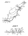
- a first embodiment of a device according to the single simplified invention for mooring and loading or unloading of a tanker is of the type comprising an underwater pipe 1 of supply or discharge of fluid to which is connected at least one flexible tube 2 resistant to torsional forces by means of a Pipe End Module 4 resting on the seabed 5, comprising an orifice 6 for connection to the Flexible Tube 2; the free end 8 of the flexible tube 2 being provided connectable to conduits or manifoidsIO, 12 for loading or unloading provided on the tanker 14.
- this device is characterized in that the Pipe End Module 4 comprises means 16 for mooring the tanker 14 and the Pipe End Module 4 is provided with a sufficient pass for supporting the traction of the ship 14.
- the flexible tube 2 is connected at least temporarily to the ducts or manifolds 10, 12 for loading or unloading provided on the ship 14 by means of an End Module of Flexible 18 comprising at least one rotary joint 20 put into rotation during pivoting or drifts of the ship 14 under the effect of external elements, such as prevailing wind, current and swell, thanks to the quasi-deformation in torsion of the flexible tube 2.
- the flexible tube 2 is partially submarine and comprises in its submerged part floats 22 designed to give it an apparent weight almost zero in water, while for its emerged part the flexible tube 2 comprises floats 24 certainly positive buoyancy.
- This flexible tube 2 must naturally be of length and have sufficient bending properties to allow deformation in harmonious curves and of radius compatible with the torsional stiffness of the flexible or flexible tube 2 which is therefore generally made of reinforced rubber. This deformation without wrinkling or crushing is further facilitated by the state close to weightlessness in which the submerged part of the hose 2 is located.
- the Flexible End Module 18 is shown moored laterally to the ship 14 using hawsers 26, 28 and therefore the End Module of Flexible 18 includes means 30, 32 for mooring hawsers 26, 28, such as rings.
- the hose end module 18 has the rotary joint 20 which is incorporated in its mass.
- the free end 8 of the flexible tube 2 is connected to a part of the rotary joint 20 while the flexible end module 18 is connected to the other part of the rotary joint 20 or forms an integral part of this other part, that is to say that in fact the flexible tube 2 is rotatably mounted relative to the hose end module 18.
- the hose end module 18 is essentially constituted by a hollow structure which can be metallic and closed at its free end 18a opposite the side where the rotary joint 20 is located.
- the hose end module 18 can include compartments forming integrated floats to ensure positive buoyancy.
- the hose end module can serve as a manifold and be equipped with one or more shut-off valves 34, 36 from which a flexible tributary tube associated 38 , 40 which generally has a smaller diameter than the main flexible tube 2 and individually leading to the conduits 10, 12 of the ship 14.
- the hose end module 18 it is advantageous in this case for the hose end module 18 to have flexible fenders 42, 44 avoiding deterioration during contact with the ship 14.
- the hose end module may be reduced to a rotating joint 20 which it is then possible to lift out water to connect it directly to one of the pipes 10, 12 of the ship 14.
- connection orifice 6 of the pipe end module 4 with the flexible tube 2 is not necessarily located in the extension of the subsea pipe 1 and can be located at the rear of the module pipe end 4 being located in a vertical plane, as shown at 50, and then the flexible tube 2 has the position indicated in phantom lines 2 '.
- connection orifice 6 of the pipe end module 4 with the flexible tube 2 is not necessarily located in the extension of the subsea pipe 1 and can be located at the rear of the module pipe end 4 being located in a vertical plane, as shown at 50, and then the flexible tube 2 has the position indicated in phantom lines 2 '.
- a hawser 52 has one of its ends permanently fixed to the mooring means 16 and is provided so as to have its free positive flotation end which can end in a marking float facilitating fishing of the hawser 52 as for the hose end module 18.
- the pipe end module 4 can also serve as a manifold and include one or more valves such as 54.
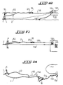
- the Flexible End Module 18 can be in an advantageous embodiment fixed on the vessel 14 and preferably at its bow, as shown in Figures 3 and 4.
- the flexible tube 2 comprises at its free end a simple shutter and the Flexible End Module 18 includes a quick coupler associated with its rotary joint 20.
- the hawser 52 and the flexible tube 2 both terminate at the bow of the ship 14 at neighboring points but with the Flexible End Module 18 slightly away from the 'axis XX of the ship 14 which is necessarily reserved for the fixing of the hawser 52.
- This arrangement is particularly advantageous in the case of rough seas, on an underwater oil field served by ships which would be specially affected.
- the flexible tube is advantageously shorter than in the more frequent case of a connection to the standard median manifold of the ship, as shown in FIGS. 1 and 2.
- hawsers 52 which are generally made of nylon or polypropylene, are subject to fatigue caused by variations in tension and end up breaking if they are not replaced in time.
- a hawser 52 which leads directly to the End of Driving Module 4 requires to be connected to the mooring means 16 or to be disconnected from it, by plunger.
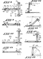
- This drawback can be eliminated by modifying the Pipe End Module as shown in FIGS. 5 to 7, so that it comprises a rod 60 articulated at 62 at its base on the body 63 of the Pipe End Module 4 resting on the seabed.
- This rod 60 is advantageously provided with a float 65 so as to have its free end, when a ship is not moored to the End of Driving Module 4 flush with or exceeding the surface of the water so as to be easily locatable and accessible, said free end comprising the aforementioned mooring means 16 of the hawser 52 which is advantageously provided floating and with a locating buoy to facilitate fishing.
- FIG. 6 an embodiment of the articulation 62 between the rod 60 and the Pipe End Module 4 is shown. This articulation is here produced by two interlaced rings 66, 68.
- a preferred embodiment is that shown in FIG. 7 according to which the rod 60 is articulated to the Flexible End Module 4 by an articulation forming a mechanical joint with the universal joint which is advantageous because of low clearance.
- FIG. 8 to 11 there is shown one of the currently preferred embodiments of the Driving End Module according to the invention which here has substantially the shape of a "T with preferably the leg of the" T located in the extension of the underwater pipe 1.
- the Pipe End module either in a "T" shape or not, consists essentially of a closed hollow structure comprising transverse partitions such as 70, 71, 72 internal watertightings defining independent compartments such as 73, 74, 75, 76 ballastable.
- the Pipe End Module 4 comprises a rear part 80 fixed to the underwater pipe 1 and comprising an orifice 82 for communication with the underwater pipe 1 and for connection with the flexible tube 2 and a second front part 84 articulated by an articulation 86 to the rear part 80 to be pivotable relative to the rear part 80 either in a vertical plane passing through the axis of the underwater pipe 1, or in a vertical plane perpendicular to the axis of the underwater pipe 1, or both.
- this articulation is formed by a shaft 88 which can be seen clearly in FIG. 9 perpendicular to the axis of the underwater pipe 1 and crossing the rear part 80 on the ends of which is fixed a fork 90 secured to the leg 91 of the "T".
- This arrangement allows pivoting in a vertical plane passing through the axis of the underwater pipe 1, of the front part 84 relative to the rear part 80 of the Pipe End Module 4.
- the horizontal bar 92 of the "T" comprising, on either side, teeth or spades 94 for anchoring the Pipe End Module 4 to the seabed, said teeth or spades 94, are preferably constituted by flat panels or tubes open at their lower end.
- Pipe End Module is the “L” shape shown in FIGS. 12 to 15.
- the “L” Pipe End Module also includes compartments 100, 101, 102, 103 ballastable that is ballasted quickly or instantaneously on the site, as shown in FIG. 15 and in this case the bar 104 of the "L forming the End of Driving Module 4 has at its free end teeth 105 or spades as in the case of the T-End Driving Module of Figures 8 to 11 to ensure dynamic self-anchoring of the Driving End Module in accordance with the method of the present invention.
- the Driving End Module comprises hauling means 106 such as a ring in the extension of the bar of the "L" coaxial with the underwater pipe 1.
- the branch 104 of the “L” during the ballasting of the non-ballasted compartments located in the branch 104 causes pivoting around the pipe 1.
- the flexible tube is preferably connected to a connection orifice 112 situated at the rear of the Pipe End Module in a vertical plane as can be seen in FIG. 12.
- the present invention therefore makes it possible to obtain a dynamic self-anchoring in a particularly simple manner while facilitating the operation of installing the underwater pipe 1 and the simplified mooring device according to the invention.
- the End Pipe Module can also be provided on land with all the accessories necessary to make the unique complete device according to the invention for mooring and loading or unloading of fluid.
- Figures 16 and 17 show this preferred feature of the process for implementation.
- FIG. 16 shows the pulling cable 118 connected to a winch 120 of a draft barge 122, an auxiliary winch 124 being provided for pulling an auxiliary cable 126 for drawing the hose end module 18.
- Figure 17 shows the plan view of this assembly.
- the floating hawser 52 can be provided with an hawser touline 130 with floating marker 132 and likewise the floating hose end module 18 can be provided with a hawser 134 also comprising floating markers 136 facilitating fishing for example by a grapple 138 from the tanker 14 or tanker.
- the flexible pipes and the hawsers tend to s '' wrap around the buoy due to changes in the direction of the current or wind, which causes them damage by friction and requires the presence of a service speedboat at the terminal, in order to untangle these lines before use. This often requires in known devices to anchor them in a fixed direction by means of dead bodies that the service speedboat must go up to the surface when a ship presents itself and then the speedboat directs the hawser and the floating pipe in the direction of the ship .
- the device according to the invention has the considerable advantage of not using an underwater rotating joint which is inaccessible from the surface for monitoring and maintenance and / or directly or indirectly subjected to mooring pulls.
- the flexible pipe goes directly and quite naturally from the underwater pipe 1 to the ship without having to pass through a buoy.
- the single simplified device for mooring and loading or unloading of fluid according to the invention makes it possible to significantly reduce the installation cost and its cost increases significantly less with the depth of the water than in the case of anterior buoy devices.
- the pipe end module 4 can have other shapes and in particular a "1" shape.
Landscapes
- Chemical & Material Sciences (AREA)
- Engineering & Computer Science (AREA)
- Combustion & Propulsion (AREA)
- Mechanical Engineering (AREA)
- Ocean & Marine Engineering (AREA)
- Laying Of Electric Cables Or Lines Outside (AREA)
- Forklifts And Lifting Vehicles (AREA)
- Ship Loading And Unloading (AREA)
Applications Claiming Priority (2)
| Application Number | Priority Date | Filing Date | Title |
|---|---|---|---|
| FR8217400A FR2534545A1 (fr) | 1982-10-18 | 1982-10-18 | Dispositif simplifie unique d'amarrage et de chargement ou de dechargement de navires-citernes, a partir d'une conduite sous-marine d'alimentation ou d'evacuation en fluide, et procede de mise en place de la conduite sous-marine et du dispositif simplifie d'amarrage |
| FR8217400 | 1982-10-18 |
Publications (2)
| Publication Number | Publication Date |
|---|---|
| EP0107999A1 EP0107999A1 (fr) | 1984-05-09 |
| EP0107999B1 true EP0107999B1 (fr) | 1986-12-30 |
Family
ID=9278350
Family Applications (1)
| Application Number | Title | Priority Date | Filing Date |
|---|---|---|---|
| EP83402015A Expired EP0107999B1 (fr) | 1982-10-18 | 1983-10-17 | Dispositif simplifié unique d'amarrage et de chargement ou de déchargement de navires-citernes, à partir d'une conduite sous-marine d'alimentation ou d'évacuation en fluide, et procédé de mise en place de la conduite sous-marine et du dispositif simplifié d'amarrage |
Country Status (5)
| Country | Link |
|---|---|
| US (1) | US4587919A (OSRAM) |
| EP (1) | EP0107999B1 (OSRAM) |
| JP (1) | JPS5992291A (OSRAM) |
| DE (1) | DE3368570D1 (OSRAM) |
| FR (1) | FR2534545A1 (OSRAM) |
Families Citing this family (11)
| Publication number | Priority date | Publication date | Assignee | Title |
|---|---|---|---|---|
| GB2296904B (en) * | 1995-03-03 | 1996-12-18 | Victoria Oilfield Dev | Mooring and Flowline System |
| US5944448A (en) * | 1996-12-18 | 1999-08-31 | Brovig Offshore Asa | Oil field installation with mooring and flowline system |
| US5927316A (en) * | 1997-09-05 | 1999-07-27 | Suburban Propane, L.P. | Safety cut-off system |
| EP0962384A1 (en) * | 1998-06-05 | 1999-12-08 | Single Buoy Moorings Inc. | Loading arrangement |
| RU2200109C1 (ru) * | 2002-03-29 | 2003-03-10 | Открытое акционерное общество "Мурманское морское пароходство" | Комплекс для передачи жидкого груза на танкер (варианты) |
| US6824330B2 (en) * | 2002-09-19 | 2004-11-30 | Coflexip S.A. | Constant tension steel catenary riser system |
| RU2250177C1 (ru) * | 2004-04-15 | 2005-04-20 | Открытое акционерное общество "Мурманское морское пароходство" | Комплекс для передачи жидкого груза на танкер |
| EP2356018B1 (en) * | 2008-11-20 | 2017-05-03 | Single Buoy Moorings Inc. | Floating multi-function unit for the offshore transfer of hydrocarbons |
| RU2412079C1 (ru) * | 2010-01-20 | 2011-02-20 | Открытое акционерное общество "Мурманское морское пароходство" | Шланг-швартов для одноопорной швартовки судов и транспортирования по нему текучей среды |
| AU2014224154B8 (en) * | 2014-07-09 | 2015-07-02 | Woodside Energy Technologies Pty Ltd | System and method for heading control of a floating lng vessel using a set of real-time monitored cargo containment system strain data |
| JP6378954B2 (ja) * | 2014-07-10 | 2018-08-22 | 新日鉄住金エンジニアリング株式会社 | 浮体係留装置 |
Family Cites Families (12)
| Publication number | Priority date | Publication date | Assignee | Title |
|---|---|---|---|---|
| NL302481A (OSRAM) * | 1963-02-20 | 1900-01-01 | ||
| US3204658A (en) * | 1963-02-26 | 1965-09-07 | Suzuki Eiji | Loading and unloading apparatus for carrying liquids between a floating ship and land |
| GB1177926A (en) * | 1966-05-06 | 1970-01-14 | Shell Int Research | One Point Mooring System for Loading Fluids into or Unloading Fluids from a Ship |
| US3455270A (en) * | 1968-05-08 | 1969-07-15 | Exxon Research Engineering Co | Protective dome for underwater mooring swivel |
| US3837380A (en) * | 1971-03-29 | 1974-09-24 | R Davies | Marine loading/unloading system |
| US3700014A (en) * | 1971-04-30 | 1972-10-24 | Bethlehem Steel Corp | Apparatus for transferring fluid from an underwater storage unit to a floating vessel |
| DE2134470A1 (de) * | 1971-07-10 | 1973-01-25 | Texaco Development Corp | Anker- und ladeanlage |
| US3840927A (en) * | 1973-04-27 | 1974-10-15 | Imodco | Swivel unit for mooring and cargo transfer system |
| US3979785A (en) * | 1974-08-09 | 1976-09-14 | Exxon Research And Engineering Company | Combined catenary and single anchor leg mooring system |
| CA1112520A (en) * | 1977-01-03 | 1981-11-17 | John F. Flory | Riser and yoke mooring system |
| US4326312A (en) * | 1979-04-30 | 1982-04-27 | Amtel, Inc. | Single leg mooring terminal |
| US4387660A (en) * | 1979-07-17 | 1983-06-14 | Morrison-Knudsen Company, Inc. | Single point mooring |
-
1982
- 1982-10-18 FR FR8217400A patent/FR2534545A1/fr active Granted
-
1983
- 1983-03-29 US US06/480,118 patent/US4587919A/en not_active Expired - Fee Related
- 1983-10-17 DE DE8383402015T patent/DE3368570D1/de not_active Expired
- 1983-10-17 EP EP83402015A patent/EP0107999B1/fr not_active Expired
- 1983-10-18 JP JP58195124A patent/JPS5992291A/ja active Pending
Also Published As
| Publication number | Publication date |
|---|---|
| JPS5992291A (ja) | 1984-05-28 |
| US4587919A (en) | 1986-05-13 |
| FR2534545B1 (OSRAM) | 1985-01-11 |
| EP0107999A1 (fr) | 1984-05-09 |
| FR2534545A1 (fr) | 1984-04-20 |
| DE3368570D1 (en) | 1987-02-05 |
Similar Documents
| Publication | Publication Date | Title |
|---|---|---|
| EP3854670B1 (fr) | Procédé d'installation d'une éolienne offshore munie d'une structure de support flottant | |
| EP2252501B1 (fr) | Support flottant equipe de touret comprenant des paliers de roulement hors d'eau | |
| EP0107999B1 (fr) | Dispositif simplifié unique d'amarrage et de chargement ou de déchargement de navires-citernes, à partir d'une conduite sous-marine d'alimentation ou d'évacuation en fluide, et procédé de mise en place de la conduite sous-marine et du dispositif simplifié d'amarrage | |
| EP2342488B1 (fr) | Procédé de montage d'une tour d'exploitation d'un fluide dans une étendue d'eau et tour d'exploitation associée | |
| EP1913229B1 (fr) | Installation sous-marine équipée d'une conduite flexible à courbure contrôlée | |
| OA12814A (en) | Système de colonne mo ntante flexible. | |
| CA2076867C (fr) | Systeme de chargement pour milieux aquatiques | |
| FR2544688A1 (fr) | Systeme modulaire de production, de stockage et de chargement d'hydrocarbures au large des cotes | |
| EP0307255B1 (fr) | Ligne d'ancrage caténaire pour un engin flottant et dispositif et procédé de mise en oeuvre de cette ligne d'ancrage | |
| OA12820A (en) | Système de colonne montante reliant deux installations sous-marines fixes à une unité de surface flottante. | |
| AU701392B2 (en) | Arrangement in a loading/unloading buoy for use in shallow waters | |
| EP3286069B1 (fr) | Support flottant avec section horizontale variable avec la profondeur | |
| FR2636670A1 (fr) | Methode et dispositif d'amarrage et de connexion d'une extremite de ligne flexible avec une conduite d'un edifice marin flottant | |
| EP2571753B1 (fr) | Installation de liaison fond-surface comprenant une structure de guidage de conduite flexible | |
| CA2280403C (fr) | Procede d'implantation d'une installation d'exploitation | |
| FR2913033A1 (fr) | Dispositif d'ancragee semi permanent/permanent destine a amarrer des corps flottants | |
| FR2938001A1 (fr) | Procede de montage d'une tour d'exploitation d'un fluide dans une etendue d'eau et tour d'exploitation associee. | |
| FR2656274A1 (fr) | Dispositif de chargement en mer de tanker. | |
| FR3093699A1 (fr) | Flotteur d’éolienne semi-submersible, ensemble d’éolienne et procédé d’ancrage associés | |
| WO2015136183A1 (fr) | Stoppeur de chaîne pour unité flottante et système d'ancrage pour unité flottante associé | |
| FR2959477A1 (fr) | Mouillage non impactant bout et tubes | |
| MC1342A1 (fr) | Bouee d'amarrage pour bateaux-citerne | |
| FR3066753A1 (fr) | Tige d'amarrage d'une bouee d'amarrage | |
| FR2768118A1 (fr) | Dispositif de mouillage d'un tanker de dechargement d'une installation marine de production et de stockage de produits petroliers | |
| EP0135445A1 (fr) | Système d'amarrage d'un corps flottant de grandes dimensions notamment en mer |
Legal Events
| Date | Code | Title | Description |
|---|---|---|---|
| PUAI | Public reference made under article 153(3) epc to a published international application that has entered the european phase |
Free format text: ORIGINAL CODE: 0009012 |
|
| AK | Designated contracting states |
Designated state(s): BE CH DE GB IT LI NL SE |
|
| 17P | Request for examination filed |
Effective date: 19840625 |
|
| GRAA | (expected) grant |
Free format text: ORIGINAL CODE: 0009210 |
|
| AK | Designated contracting states |
Kind code of ref document: B1 Designated state(s): BE CH DE GB IT LI NL SE |
|
| PG25 | Lapsed in a contracting state [announced via postgrant information from national office to epo] |
Ref country code: NL Effective date: 19861230 Ref country code: IT Free format text: LAPSE BECAUSE OF FAILURE TO SUBMIT A TRANSLATION OF THE DESCRIPTION OR TO PAY THE FEE WITHIN THE PRESCRIBED TIME-LIMIT;WARNING: LAPSES OF ITALIAN PATENTS WITH EFFECTIVE DATE BEFORE 2007 MAY HAVE OCCURRED AT ANY TIME BEFORE 2007. THE CORRECT EFFECTIVE DATE MAY BE DIFFERENT FROM THE ONE RECORDED. Effective date: 19861230 |
|
| PG25 | Lapsed in a contracting state [announced via postgrant information from national office to epo] |
Ref country code: SE Effective date: 19861231 |
|
| REF | Corresponds to: |
Ref document number: 3368570 Country of ref document: DE Date of ref document: 19870205 |
|
| NLV1 | Nl: lapsed or annulled due to failure to fulfill the requirements of art. 29p and 29m of the patents act | ||
| PLBE | No opposition filed within time limit |
Free format text: ORIGINAL CODE: 0009261 |
|
| STAA | Information on the status of an ep patent application or granted ep patent |
Free format text: STATUS: NO OPPOSITION FILED WITHIN TIME LIMIT |
|
| PG25 | Lapsed in a contracting state [announced via postgrant information from national office to epo] |
Ref country code: LI Effective date: 19871031 Ref country code: CH Effective date: 19871031 Ref country code: BE Effective date: 19871031 |
|
| 26N | No opposition filed | ||
| BERE | Be: lapsed |
Owner name: TRAMCO S.A. Effective date: 19871031 |
|
| REG | Reference to a national code |
Ref country code: CH Ref legal event code: PL |
|
| PG25 | Lapsed in a contracting state [announced via postgrant information from national office to epo] |
Ref country code: DE Effective date: 19880701 |
|
| PGFP | Annual fee paid to national office [announced via postgrant information from national office to epo] |
Ref country code: GB Payment date: 19931011 Year of fee payment: 11 |
|
| PG25 | Lapsed in a contracting state [announced via postgrant information from national office to epo] |
Ref country code: GB Effective date: 19941017 |
|
| GBPC | Gb: european patent ceased through non-payment of renewal fee |
Effective date: 19941017 |