EP0107820A2 - Visiervorrichtung für Roboter - Google Patents
Visiervorrichtung für Roboter Download PDFInfo
- Publication number
- EP0107820A2 EP0107820A2 EP83109972A EP83109972A EP0107820A2 EP 0107820 A2 EP0107820 A2 EP 0107820A2 EP 83109972 A EP83109972 A EP 83109972A EP 83109972 A EP83109972 A EP 83109972A EP 0107820 A2 EP0107820 A2 EP 0107820A2
- Authority
- EP
- European Patent Office
- Prior art keywords
- planar light
- light beam
- light beams
- pickup device
- light
- Prior art date
- Legal status (The legal status is an assumption and is not a legal conclusion. Google has not performed a legal analysis and makes no representation as to the accuracy of the status listed.)
- Granted
Links
Images




Classifications
-
- G—PHYSICS
- G01—MEASURING; TESTING
- G01B—MEASURING LENGTH, THICKNESS OR SIMILAR LINEAR DIMENSIONS; MEASURING ANGLES; MEASURING AREAS; MEASURING IRREGULARITIES OF SURFACES OR CONTOURS
- G01B11/00—Measuring arrangements characterised by the use of optical techniques
-
- B—PERFORMING OPERATIONS; TRANSPORTING
- B25—HAND TOOLS; PORTABLE POWER-DRIVEN TOOLS; MANIPULATORS
- B25J—MANIPULATORS; CHAMBERS PROVIDED WITH MANIPULATION DEVICES
- B25J19/00—Accessories fitted to manipulators, e.g. for monitoring, for viewing; Safety devices combined with or specially adapted for use in connection with manipulators
- B25J19/02—Sensing devices
- B25J19/021—Optical sensing devices
- B25J19/023—Optical sensing devices including video camera means
-
- G—PHYSICS
- G01—MEASURING; TESTING
- G01S—RADIO DIRECTION-FINDING; RADIO NAVIGATION; DETERMINING DISTANCE OR VELOCITY BY USE OF RADIO WAVES; LOCATING OR PRESENCE-DETECTING BY USE OF THE REFLECTION OR RERADIATION OF RADIO WAVES; ANALOGOUS ARRANGEMENTS USING OTHER WAVES
- G01S17/00—Systems using the reflection or reradiation of electromagnetic waves other than radio waves, e.g. lidar systems
- G01S17/02—Systems using the reflection of electromagnetic waves other than radio waves
- G01S17/06—Systems determining position data of a target
-
- G—PHYSICS
- G06—COMPUTING OR CALCULATING; COUNTING
- G06T—IMAGE DATA PROCESSING OR GENERATION, IN GENERAL
- G06T1/00—General purpose image data processing
- G06T1/0014—Image feed-back for automatic industrial control, e.g. robot with camera
Definitions
- the present invention 'relates to a method of detecting the position and posture of an object to be handled by sensing the optical image of the object and analyzing it, and an apparatus for performing the method.
- the present invention relates to a robot vision system which detects the position and posture of an object to be handled by sensing the optical image of the object and analytically processing it, the detected results being used for controlling the arm mechanism of a robot.
- the present invention relates to a robot vision system which is well suited for installation on, especially, the hand of a robot, among robot vision systems which detect the position and posture of an object to be handled in an assembling operation to be executed by a robot.
- the object in a case where the object needs to be grasped or to have a component mounted thereon as in an assembling operation which is executed by a robot, the object must lie at a known distance from the detector. Accordingly, the system resorting to the binary-coded picture has the disadvantage that the objects to be handled are limited.
- an NBS system (VanderBrug, G. J., et. a "A Vision System for Real Time Control of Robots", 9th Int. Symp. on Industrial Robots, pp. 213 - 230, 1979) has been devised.
- a robot arm carrying the detector thereon needs to be moved so as to view the object from several different angles. This leads to take a long time for the detection.
- An object of the present invention is to eliminate the disadvantages of the prior arts described above, and to provide a method of detecting the position and posture of an object to be handled at high speed, as well as a small-sized and light-weight detection device for realizing the method.
- Another object of the present invention is to provide a snail-sized, light-weight vision system which detects three-dimensional positions and postures of objects at high speed without being effected by color or contrast between the object and its background, and which can be mounted on the hand of a robot.
- Another object of the present invention is to provide a small-sized and light-weightrobot vision'system which detects the three-dimensional position and posture of an object to be handled at high speed without being affected by the color and brightness of the object.
- a method of detecting the position and posture of an object according to the present invention is characterized by two planar light beams alternately projected on the object to be handled. Intersection lines between the planar light beams and a surfac of the object to be handled are imaged by a single image pickup device in a position between the two planar light beams. A bright line in a ' picture of the image thus obtained is separated and extracted, and the bright line is transformed into an actual coordinate in a three dimensional coordinate system by referring to a corresponding relationship, obtained in advance, between actual positions and a real positions in a reference picture, and is then analyzed to provide the position and posture of the object to be handled in three dimensions.
- a device for detecting the position and posture of an object according to the present invention is also characterized by light sources which generate two planar light beams, a device which controls the light sources so as to switch and emit the two planar light beams, a single image pickup device which forms images of intersection lines betweer the planar light beams and the object to be handled and which i positioned between the planar light beams, a device which separates and extracts a bright line on a picture thus obtaine a device which stores a corresonding relationship between the line thus separated and extracted and actual coordinate positions, and computation means for analyzing the separated and extracted line by comparing it with the stored correspond: relationship.
- the distance of the object from the detector and the lateral position thereof can be detected by extracting the light segment waveform and then detecting and processing the positions of points a and a' on the picture in Figure 2.
- the distance of the object from the detector and the lateral position thereof can be detected by extracting the light segment waveform and then detecting and processing the positions of points a and a' on the picture in Figure 2.
- by detecting an angle a it is possible to detect the rotational angle of the surface of the object 5 about an axis which is normal to a plane defined by the planar light beam 3.
- FIG. 3 Another system which applies the light segmentation method is shown in Figure 3.
- Two light sources la, lb are combined so as to emit planar light beams 3a, 3b intersecting each other.
- Two image pickup devices 2a, 2b are arranged for the respective planar light beam 3a, 3b, so as to image two light segments. Since such setup can detect the rotational angles of the surface of an object about two axes which are respectively normal to two non-parallel planes, the posture of the object can be detected in three dimensions without moving the detector. Moreover, besides the distance of the object from the detector, the sizes and positions of the object in two directions can be detected.
- FIG. 4 A system setup shown in Figure 4 is exemplified in order to clarify the following description which is quite similarly applicable to a setup shown in Figure 5.
- two planar light beams 3a, 3b are alternately switched and projected, and the distances, positions and inclinations of the object from the detector on two planes not parallel to each other can be found, and hence, the three-dimensional position and posture of the object can be uniquely found on the basis of them.
- the detector or the object is roughly positioned beforehand so that the intersection line 6 between the two planar light beams 3a, 3b, may intersect the surface of the object, and that the relative position and posture between the detector and the object are precisely detected by the use of the robot vision system O of the present invention.
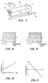
- a plane 7 which is perpendicular to the z-axis and which has an area larger than the field of view of the ima pickup device 2 is erected on a graduated rail 8 so as to be translated in the direction of the z-axis.
- the positions of the light segments on the detection picture are found while the plane 6 is being brought away from the detector at intervals of, e.g., 1 cm.
- a diagram of equidistant lines as shown in Figure 8 is obtained.
- several planes 7 which are rectangles having fixed breadths are prepared, and they are similary erected on the rail 8 perpendicularly to the z-axis and moved in the direction of the z-axis.
- the x-axial breadths of the planes 7 are set at in intervals of, e.g., 2 cm, and the loci of the end points of the light segments detected when the repective planes 7 are moved in the z-axial direction are found. Then, a diagram of equibroad lines (concerning x-coordinates) as shown in Figure 9 is obtained.
- equidistant line diagram of Figure 8 and the equibroad line diagram of Figure 9 variations in the distance and x-directional position along.certain horizontal lines h - h' on the diagrams are observed, they become as shown in Figure 10 and Figure 11, respectively.
- they are expressed as a function z of the distance and a function x of the x-directional position at vertical coordinates j on the diagrams, with a variable being lateral coordinates i on the diagrams, they can be approximated as follows:
- the planar light beam 3a on one side shown in Figure 4 will be referred to.
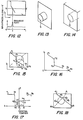
- the light segment imaged by the image pickup device 2 has a certain width due to the width of the planar light beam, the defocusing of an optical system, etc. Accordingly, the horizontal scanning direction of the image pickup device 2 is held in agreement with the direction of the line h - h' (lateral direction) shown in Figures 8 and 9, and the coordinate i of the light segment at each j (refer to Figure 12).
- the coordinates of the positions of the light segment for calculating Equations (1) and (2) are extracted.
- the approximate central position of the upper surface of the columnar object 9 in the x-direction is obtained from the middle point of the segment A having the smallest z-coordinates, namely the segment closest to the detector.
- the inclination of the object 9 in the x-z plane is found using Equation (3).
- the light sources are switched, and a light segment image (indicated by a broken line B in Figure 15)is similarly processed, thereby to find the approximate central position of the upper surface of the columnar object 9 in the y-direction and the inclination of the object 9 in the y-z plane.
- the dist z from the detector to the central position of the upper surface of the object 9 is evaluated as follows, when this upper surface of the columnar object 9 is substantially perpendicular to the z-axis: or
- x 1 and x 2 denote the x-coordinates of the end points of the light segment image on the x-z plane (A shown in Figure 15) in the upper surface of the columnar object g; y 1 and y 2 the y-coordinates of the end points of the light segment image on the y-z plane (B shown in Figure 15); and z l , z 2 , z 3 and z 4 the z-coordinates of the four end points, respectively.
- the z-axis i.c., the intersection line of the planar light beams 3a and 3b may become substantially perpendicular to the plane, whereupon the central position and distance are detected again.
- Figure 18 is a diagram showing an example of a light segment obtained when the hole 10 shown in Figure 14 has been imaged by the image pickup device.
- two light segment images on the x-z plane and y-z plane are independently detected by switching the light sources. Solid and broken lines in Figure 18 indicate the two light segment images thus obtained.
- a segment connecting points a' 2 and a' 3 and a segment connecting points b' 2 and b'3 in the figure are respectively subjected to processing corresponding to the segments A and B in Figure 15 in the foregoing example, whereby the position of the hole 10 and the direction of the formation thereof can be detected quite similary.
- Figure 19 is a diagram showing an embodiment of the whole setup of the robot vision system of the present invention.
- the detector is constructed of an image pickup device 2 and light sources la, lb, and is arranged as stated below.
- the detector is constructed on a robot arm 11. As modifications of the method of constructing the detector, there are one to four logically-possible combinations of the aforementioned (1) - (5). While, in Figure 19, the detector is fixed to a portion for rotating and driving the gripper 18 of the robot, it may well be fixed on the gripper 18 so as to be rotated unitarily with this gripper.
- the embodiment shown has two light sources to alternately project two planar light beams
- other embodiments may be constructed with a single light source to alternately project two planar light beams intersecting each other by moving (i.e., rotation) the position of the light source or by using turret lens, containing a slit, or by light filters transmitting different wavelengths, or the like.
- the robot vision system is wholly controlled by a microcomputer (or minicomputer) 15 in Figure 19. It controls a light switching device 13 so that the light sources la, lb may alternately emit the lights.
- the resulting respective light segment images are detected by the image pickup device 2.
- a detected picture signal is inputted to a light segment extracting circuit 14, and a light segment waveform is inputted to the microcomputer 15.
- the light segment extracting circuit 14 compresses two-dimensional picture data into unidimensional waveform data in accordance with the method explained before, and it may be a device disclosed in Japanese Patent Application No. 54-146427.
- the two sets of light segment waveform data thus obtained are processed in the microcomputer 15 by the procedure explained before.
- Equations (1) - (5) are performed to detect the three-dimensional position and posture of the object.
- the resulting data 17 are outputted to a control device for the robot arm mechanism.
- the light segment waveforms based on the light segment images in the case where the microcomputer 15 controls the light switching device 13 so as to cause the two light sources la, lb to emit lights respectively, are produced by the light segment extracting circuit 14 and are subjected to the polygonal line approximations by the microcomputer 15. Thereafter, the actual positional coordinates of the respective segments are evaluated on the basis of the coefficients a. , b. stored in the memory 16 and by the use of Equations (1), (2) (and a similar equation for obtaining y j ).
- the microcomputer 15 selects one segment on the object for each light source, with the distance z as a criterion (usually, the segment which is nearest to the detector and which lies near the middle of the field of view). On the basis of the four end points of such two segments, the microcomputer computes Equations (3) - (5) and the middle points of the . segments, to detect the position and posture of the object and to output them to the control device of the robot arm mechanism.
- a TV camera is employed as the image pickup device 2, and it can detect the light segment at high speed by bringing the horizontal scanning direction into agreement with the direction of i indicated in Figure 12.
- a two-dimensional picture detector other than the TV camera for example, the combination of a linear photodiode array and a galvano-scanning mirror.
- amoung the TV cameras, especially one employing an areal solid-state image sensor is superior to one employing an electron tube in the five points of (i) earthquake-proof and shock resistance, (ii) lifetime, (iii) picture distortion, (iv) small size and light weight, and (v) saving in electric power.
- Figure 20 is a view showing a practical embodiment of the image pickup device employing such areal solid-state image sensor 19, a picture signal pre-amplifier 20 and a synchronous drive signal waveshaping circuit 21, as shown in Figure 21.
- -A TV camera control unit 22 will not typically be carried by the robot arm.
- the image pickup device is rendered still smaller in size and light in weignt.
- the picture signal pre-amplifier 20 is mounted on a substrate 23a, while the areal solid-state image sensor 19 and the synchronous drive signal waveshaping circuit 21 are mounted on a substrate 23b. These substrates are fixed on a rear cover 25 by a stanchion 24.
- the rear cover 25 has a connector 26 attached thereto, through which all signals and power sources are supplied.
- the rear cover 25 and an outer frame 27 are made of a nonmetal such as plastics, the inner surfaces of which have copper foils stuck for electrostatic shielding (or are plated with a metal). Further, it is possible to use an imaging lens 28 made of plastics. As thus far described, when the image pickup device according to the present embodiment is used, there is the effect that the detector can be made remarkably small in size and light in weight, in addition to the features of earthquake-proof and shock resistance, long lifetime, low picture distortion and saving in electric power.
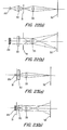
- FIG. 22(a) and 22(b) show a-practical embodiment of the light source employing the light emitting diode.
- the light emitting diode 29 a high power type emitting infrared radiation is used.
- the maximum sensitivity wavelength of the areal solid-state image sensor is near 800 nm.
- the detection sensitivity can be maximized.
- a plurality of such light emitting diodes 29 are arrayed in a row in agreement wit: the lengthwise direction of a cylindrical lens 30.
- the light emitting diodes 29 and a slit 31 are in imaging relationship with respect to the cylindrical lens 30.
- the position of an imaging plane 32 is set at the rough position of the object, and the imaging plane 32 and the slit 31 lie in imaging relationship with respect to an imaging lens 33.
- the planar light beam can be formed by efficiently condensing lights emitted from the light emitting diodes 29. Therefore, the light source which is bright besides the aforementioned three features can be realized. Further, when a type of high directivity employing a lens is used as the light emitting diode 29, a more powerful light source can be realized.
- Figures 23(a) and 23(b) show another practical embodiment of the light source employing the light emitting diode.
- a plurality of light emitting diodes 29 are arranged along a slit 31, and the slit 31 and an imaging plane 32 lie in imaging relationship with respect to an imaging lens 33.
- a cylindrical lens 30 is inserted between the imaging lens 33 and the slit 31 so as to prevent the slit light from becoming non-uniform on the imaging plane 32.
- the present embodiment has the drawback that the planar light beam becomes ununiform when the imaging relationship of the imaging plane 32 deviates, it can be ignored in the present invention for detecting the position of the light segment.
- the present embodiment can reduce the length in the optical axis direction. This brings forth the feature that the light source can be made remarkably small in size, besides the features possessed by the light emitting diodes 29.
- the outer frame of the light source is made of a nonmetal such as plastics, as in an image pickup device, there is the effect that the detector can be rendered conspicuously small in size and light in weight.
- the planar light beam does not become perfectly flat in some cases. This problem can be avoided in such a way that the diameter of the imaging lens 33 is not unnecessarily made large.
- light sources are so arranged that two planar light beams intersect each other, and respective light segments thus obtained are analyzed, whereby the positions and postures of an object to be handled in two non-parallel planes can be detected without moving a detector or the object. This brings forth the effect that the three-dimensional position and posture of the object can be detected at high speed.
- an image pickup device and the light sources can be made unitary. This permits a small-sized, light-weight detector to be attained, and allows detection to occur without operation of the detector being effected by the gripper of a robot or an object grasped by the gripper. Moreover, light segments in two non-parallel planes are detected by the single image pickup device. This assures that the detector can be made small in size and light in weight.
- use of the light segmentation method, on which the present invention is grounded permits the detection of the position and posture of an object without operation or accuracy being effected by the ontrast, color or surface condition of the object.
Landscapes
- Engineering & Computer Science (AREA)
- Physics & Mathematics (AREA)
- General Physics & Mathematics (AREA)
- Electromagnetism (AREA)
- Robotics (AREA)
- Computer Networks & Wireless Communication (AREA)
- Mechanical Engineering (AREA)
- Multimedia (AREA)
- Radar, Positioning & Navigation (AREA)
- Remote Sensing (AREA)
- Theoretical Computer Science (AREA)
- Length Measuring Devices By Optical Means (AREA)
- Image Analysis (AREA)
- Manipulator (AREA)
Applications Claiming Priority (6)
| Application Number | Priority Date | Filing Date | Title |
|---|---|---|---|
| JP17452282A JPS5965203A (ja) | 1982-10-06 | 1982-10-06 | 物体の位置および姿勢検出方法および装置 |
| JP174522/82 | 1982-10-06 | ||
| JP19747382A JPS5988297A (ja) | 1982-11-12 | 1982-11-12 | 対象物体の位置及び姿勢検出装置並びにその方法 |
| JP197473/82 | 1982-11-12 | ||
| JP201931/82 | 1982-11-19 | ||
| JP20193182A JPS5993293A (ja) | 1982-11-19 | 1982-11-19 | 視覚装置 |
Publications (3)
| Publication Number | Publication Date |
|---|---|
| EP0107820A2 true EP0107820A2 (de) | 1984-05-09 |
| EP0107820A3 EP0107820A3 (en) | 1986-03-26 |
| EP0107820B1 EP0107820B1 (de) | 1990-01-17 |
Family
ID=27323955
Family Applications (1)
| Application Number | Title | Priority Date | Filing Date |
|---|---|---|---|
| EP83109972A Expired EP0107820B1 (de) | 1982-10-06 | 1983-10-05 | Visiervorrichtung für Roboter |
Country Status (3)
| Country | Link |
|---|---|
| US (1) | US4611292A (de) |
| EP (1) | EP0107820B1 (de) |
| DE (1) | DE3381117D1 (de) |
Cited By (8)
| Publication number | Priority date | Publication date | Assignee | Title |
|---|---|---|---|---|
| FR2576005A1 (fr) * | 1985-01-15 | 1986-07-18 | Realisa Indles Et | Procede et dispositif automatique de depalettisation |
| EP0220571A1 (de) * | 1985-10-14 | 1987-05-06 | Hitachi, Ltd. | Verfahren und Vorrichtung zum Ausrichten |
| EP0156342A3 (en) * | 1984-03-26 | 1988-08-10 | Hitachi, Ltd. | Three-dimensional vision system |
| EP0212992A3 (en) * | 1985-05-20 | 1988-10-05 | Fujitsu Limited | Method for measuring a three-dimensional position of an object |
| EP0290633A1 (de) * | 1987-05-09 | 1988-11-17 | Carl Schenck Ag | Verfahren zum Erkennen von Änderungen in Fahrraum eines unbemannten Fahrzeuges |
| EP0364614A1 (de) * | 1988-10-17 | 1990-04-25 | Siemens Aktiengesellschaft | Verfahren zur Erkennung der räumlichen Lage und Orientierung vorher bekannter Körper |
| FR2643707A1 (fr) * | 1989-02-24 | 1990-08-31 | Syspro | Dispositif de reconnaissance de position d'objets |
| EP0571769A3 (de) * | 1992-05-29 | 1994-03-02 | Nippon Kogaku Kk |
Families Citing this family (57)
| Publication number | Priority date | Publication date | Assignee | Title |
|---|---|---|---|---|
| US4686639A (en) * | 1985-02-07 | 1987-08-11 | Rockwell International Corporation | Free space microscope digitizing aid |
| US4727471A (en) * | 1985-08-29 | 1988-02-23 | The Board Of Governors For Higher Education, State Of Rhode Island And Providence | Miniature lightweight digital camera for robotic vision system applications |
| JPH0679325B2 (ja) * | 1985-10-11 | 1994-10-05 | 株式会社日立製作所 | 位置姿勢判定方法 |
| US4753357A (en) * | 1985-12-27 | 1988-06-28 | Ishikawajima-Harima Heavy Industries Co., Ltd. | Container crane |
| US4825393A (en) * | 1986-04-23 | 1989-04-25 | Hitachi, Ltd. | Position measuring method |
| US4918627A (en) * | 1986-08-04 | 1990-04-17 | Fmc Corporation | Computer integrated gaging system |
| US4868473A (en) * | 1987-02-24 | 1989-09-19 | Mitsubishi Denki Kabushiki Kaisha | Industrial robot device including a robot and a processing machine |
| US4876656A (en) * | 1987-08-28 | 1989-10-24 | Motorola Inc. | Circuit location sensor for component placement apparatus |
| US4961155A (en) * | 1987-09-19 | 1990-10-02 | Kabushiki Kaisha Toyota Chuo Kenkyusho | XYZ coordinates measuring system |
| US4907169A (en) * | 1987-09-30 | 1990-03-06 | International Technical Associates | Adaptive tracking vision and guidance system |
| DE3741632A1 (de) * | 1987-12-05 | 1989-06-22 | Noell Gmbh | Verfahren und vorrichtung zum erkennen und ansteuern eines raumzieles |
| US4942538A (en) * | 1988-01-05 | 1990-07-17 | Spar Aerospace Limited | Telerobotic tracker |
| US4979135A (en) * | 1988-01-27 | 1990-12-18 | Storage Technology Corporation | Vision system illumination calibration apparatus |
| US5040116A (en) * | 1988-09-06 | 1991-08-13 | Transitions Research Corporation | Visual navigation and obstacle avoidance structured light system |
| US4954962A (en) * | 1988-09-06 | 1990-09-04 | Transitions Research Corporation | Visual navigation and obstacle avoidance structured light system |
| US5005147A (en) * | 1988-12-30 | 1991-04-02 | The United States Of America As Represented By The Administrator, The National Aeronautics And Space Administration | Method and apparatus for sensor fusion |
| US4932541A (en) * | 1989-04-24 | 1990-06-12 | Calspan Corporation | Stabilized shipboard crane |
| US5051906A (en) * | 1989-06-07 | 1991-09-24 | Transitions Research Corporation | Mobile robot navigation employing retroreflective ceiling features |
| JP3251279B2 (ja) * | 1990-05-11 | 2002-01-28 | 株式会社日立製作所 | 色分布抽出方法 |
| JP3173042B2 (ja) * | 1991-05-21 | 2001-06-04 | ソニー株式会社 | ロボットの数値制御装置 |
| US5577130A (en) * | 1991-08-05 | 1996-11-19 | Philips Electronics North America | Method and apparatus for determining the distance between an image and an object |
| US5381004A (en) * | 1993-08-31 | 1995-01-10 | Applied Materials, Inc. | Particle analysis of notched wafers |
| JP3394322B2 (ja) | 1994-05-19 | 2003-04-07 | ファナック株式会社 | 視覚センサを用いた座標系設定方法 |
| US5617515A (en) * | 1994-07-11 | 1997-04-01 | Dynetics, Inc. | Method and apparatus for controlling and programming a robot or other moveable object |
| US6059268A (en) * | 1998-05-06 | 2000-05-09 | Santelli, Jr.; Albert | Bumper system for limiting the mobility of a wheeled device |
| JP3300682B2 (ja) * | 1999-04-08 | 2002-07-08 | ファナック株式会社 | 画像処理機能を持つロボット装置 |
| JP3421608B2 (ja) * | 1999-04-08 | 2003-06-30 | ファナック株式会社 | 教示モデル生成装置 |
| GB9923795D0 (en) | 1999-10-09 | 1999-12-08 | British Aerospace | Micropositioning system |
| AU2757501A (en) * | 2000-01-03 | 2001-07-16 | David J. Levenson | Adjustable ergonomic keyboard for use with stationary palm and elements thereof |
| EP1176487A1 (de) * | 2000-07-27 | 2002-01-30 | Gmd - Forschungszentrum Informationstechnik Gmbh | Autonom navigierendes Robotersystem |
| US6798527B2 (en) * | 2001-04-27 | 2004-09-28 | Minolta Co., Ltd. | Three-dimensional shape-measuring system |
| US6898484B2 (en) | 2002-05-01 | 2005-05-24 | Dorothy Lemelson | Robotic manufacturing and assembly with relative radio positioning using radio based location determination |
| JP3876234B2 (ja) * | 2003-06-17 | 2007-01-31 | ファナック株式会社 | コネクタ把持装置、同装置を備えたコネクタ検査システム及びコネクタ接続システム |
| CH697278B1 (de) * | 2003-09-12 | 2008-07-31 | Oerlikon Assembly Equipment Ag | Einrichtung und Verfahren für die Montage oder Verdrahtung von Halbleiterchips. |
| US20090099688A1 (en) * | 2005-11-10 | 2009-04-16 | Hugo Salamanca | Integral robot system and method for the dislodging process and/or anode handling from casting wheels |
| US8744624B1 (en) * | 2006-05-11 | 2014-06-03 | Kla-Tencor Corporation | Substrate alignment system |
| US8218822B2 (en) * | 2007-05-14 | 2012-07-10 | Pips Technology, Inc. | Apparatus and method for recognizing the state of origin of a vehicle license plate |
| US8082064B2 (en) * | 2007-08-24 | 2011-12-20 | Elite Engineering Corporation | Robotic arm and control system |
| EP2036660A1 (de) * | 2007-09-12 | 2009-03-18 | Hans Oxenfarth | Verfahren und Vorrichtung zur lage- und winkelkompensierten Bauteilbefestigung |
| US8941726B2 (en) * | 2009-12-10 | 2015-01-27 | Mitsubishi Electric Research Laboratories, Inc. | Method and system for segmenting moving objects from images using foreground extraction |
| US20120282064A1 (en) * | 2011-05-02 | 2012-11-08 | John Anthony Payne | Apparatus and methods of positioning a subsea object |
| US9399291B2 (en) * | 2012-12-07 | 2016-07-26 | GM Global Technology Operations LLC | Planning a grasp, for use by a robotic grasper to pick up a complex object, based on object, grasper, and grasper approach data |
| DE102013103251B4 (de) * | 2013-03-28 | 2016-05-12 | Data M Sheet Metal Solutions Gmbh | Erhöhung der Messgenauigkeit bei einer Vermessung mit Lichtschnittsensoren durch gleichzeitige Kalibrierung und Vermeidung von Speckles |
| US9245916B2 (en) | 2013-07-09 | 2016-01-26 | Rememdia LC | Optical positioning sensor |
| US10744658B2 (en) | 2014-03-04 | 2020-08-18 | Ge-Hitachi Nuclear Energy Americas Llc | Nuclear reactor light-based fuel alignment systems and methods |
| US9851196B2 (en) | 2015-04-17 | 2017-12-26 | Rememdia LC | Sensor |
| US9682481B2 (en) * | 2015-10-26 | 2017-06-20 | X Development Llc | Communication of information regarding a robot using an optical identifier |
| WO2017092809A1 (en) * | 2015-12-03 | 2017-06-08 | Abb Schweiz Ag | A method for teaching an industrial robot to pick parts |
| US10587858B2 (en) * | 2016-03-14 | 2020-03-10 | Symbol Technologies, Llc | Device and method of dimensioning using digital images and depth data |
| US10078908B2 (en) | 2016-08-12 | 2018-09-18 | Elite Robotics | Determination of relative positions |
| US10742865B2 (en) | 2017-04-14 | 2020-08-11 | International Business Machines Corporation | Configuring cognitive robot vision |
| US11285563B2 (en) * | 2017-10-20 | 2022-03-29 | Branson Ultrasonics Corporation | Fiber feedback |
| EP3776129B1 (de) | 2018-04-03 | 2025-08-20 | SharkNinja Operating LLC | Flugzeitsensoranordnung für roboternavigation und verfahren zur ortung damit |
| US20230302656A1 (en) * | 2020-07-30 | 2023-09-28 | Abb Schweiz Ag | Visual-Tactile Sensing Device for Use in Robotic Gripper |
| IT202100028412A1 (it) * | 2021-11-09 | 2023-05-09 | Marposs Spa | Calibro per apparecchiatura di controllo e metodo di messa a punto del calibro |
| US12320632B2 (en) | 2022-02-10 | 2025-06-03 | Sarcos Corp. | High resolution optical displacement measurement |
| US12313432B2 (en) | 2023-06-23 | 2025-05-27 | Sarcos Corp. | Analog optical positioning sensor, method, and circuit |
Family Cites Families (12)
| Publication number | Priority date | Publication date | Assignee | Title |
|---|---|---|---|---|
| US3806253A (en) * | 1972-12-13 | 1974-04-23 | Weyerhaeuser Co | Sweep measuring scheme |
| US3894802A (en) * | 1973-04-16 | 1975-07-15 | Bendix Corp | Stereoscopic gage and gaging system |
| DE2514930A1 (de) * | 1975-04-05 | 1976-10-14 | Opto Produkte Ag | Verfahren zur optischen ermittlung und zum vergleich von formen und lagen von objekten |
| DE2711660C3 (de) * | 1977-03-17 | 1981-06-04 | Fraunhofer-Gesellschaft zur Förderung der angewandten Forschung e.V., 8000 München | Optisches Verfahren zur Schweißbahnverfolgung |
| CA1103803A (en) * | 1978-03-01 | 1981-06-23 | National Research Council Of Canada | Method and apparatus of determining the center of area or centroid of a geometrical area of unspecified shape lying in a larger x-y scan field |
| US4305130A (en) * | 1979-05-29 | 1981-12-08 | University Of Rhode Island | Apparatus and method to enable a robot with vision to acquire, orient and transport workpieces |
| US4343553A (en) * | 1979-09-03 | 1982-08-10 | Hitachi, Ltd. | Shape testing apparatus |
| DE3175773D1 (en) * | 1980-06-10 | 1987-02-05 | Fujitsu Ltd | Pattern position recognition apparatus |
| US4399554A (en) * | 1980-08-21 | 1983-08-16 | General Motors Corporation | Method and apparatus for inspecting engine head valve retainer assemblies for missing keys |
| FR2499736B1 (fr) * | 1981-02-12 | 1987-03-06 | Renault | Dispositif et procede de localisation d'objets tridimensionnels en vrac pour la commande d'un terminal de prehension |
| US4435837A (en) * | 1981-03-05 | 1984-03-06 | President And Fellows Of Harvard College | Pattern recognition and orientation system |
| US4485409A (en) * | 1982-03-29 | 1984-11-27 | Measuronics Corporation | Data acquisition system for large format video display |
-
1983
- 1983-09-29 US US06/537,095 patent/US4611292A/en not_active Expired - Lifetime
- 1983-10-05 EP EP83109972A patent/EP0107820B1/de not_active Expired
- 1983-10-05 DE DE8383109972T patent/DE3381117D1/de not_active Expired - Lifetime
Cited By (12)
| Publication number | Priority date | Publication date | Assignee | Title |
|---|---|---|---|---|
| EP0156342A3 (en) * | 1984-03-26 | 1988-08-10 | Hitachi, Ltd. | Three-dimensional vision system |
| FR2576005A1 (fr) * | 1985-01-15 | 1986-07-18 | Realisa Indles Et | Procede et dispositif automatique de depalettisation |
| EP0212992A3 (en) * | 1985-05-20 | 1988-10-05 | Fujitsu Limited | Method for measuring a three-dimensional position of an object |
| US4846576A (en) * | 1985-05-20 | 1989-07-11 | Fujitsu Limited | Method for measuring a three-dimensional position of an object |
| EP0220571A1 (de) * | 1985-10-14 | 1987-05-06 | Hitachi, Ltd. | Verfahren und Vorrichtung zum Ausrichten |
| US4777641A (en) * | 1985-10-14 | 1988-10-11 | Hitachi, Ltd. | Method and apparatus for alignment |
| EP0290633A1 (de) * | 1987-05-09 | 1988-11-17 | Carl Schenck Ag | Verfahren zum Erkennen von Änderungen in Fahrraum eines unbemannten Fahrzeuges |
| EP0364614A1 (de) * | 1988-10-17 | 1990-04-25 | Siemens Aktiengesellschaft | Verfahren zur Erkennung der räumlichen Lage und Orientierung vorher bekannter Körper |
| FR2643707A1 (fr) * | 1989-02-24 | 1990-08-31 | Syspro | Dispositif de reconnaissance de position d'objets |
| EP0388339A3 (de) * | 1989-02-24 | 1990-11-28 | Syspro | Schaltung zur Erkennung der Lage eines Objekts |
| EP0571769A3 (de) * | 1992-05-29 | 1994-03-02 | Nippon Kogaku Kk | |
| US5369490A (en) * | 1992-05-29 | 1994-11-29 | Nikon Corporation | Contour measuring apparatus |
Also Published As
| Publication number | Publication date |
|---|---|
| DE3381117D1 (de) | 1990-02-22 |
| EP0107820B1 (de) | 1990-01-17 |
| EP0107820A3 (en) | 1986-03-26 |
| US4611292A (en) | 1986-09-09 |
Similar Documents
| Publication | Publication Date | Title |
|---|---|---|
| US4611292A (en) | Robot vision system | |
| JP3556589B2 (ja) | 位置姿勢認識装置 | |
| JP4485365B2 (ja) | 測距装置 | |
| CN100518488C (zh) | 具有元件布局检查功能的抓取式设备 | |
| CN100412501C (zh) | 图像获取设备 | |
| JP4901903B2 (ja) | 三次元検査システム | |
| US5208463A (en) | Method and apparatus for detecting deformations of leads of semiconductor device | |
| JPH0425583B2 (de) | ||
| CN102713671A (zh) | 点群数据处理装置、点群数据处理方法和点群数据处理程序 | |
| JPH02143309A (ja) | 操縦方法及び装置 | |
| Martel et al. | An active approach to solving the stereo matching problem using event-based sensors | |
| US4744664A (en) | Method and apparatus for determining the position of a feature of an object | |
| US4760269A (en) | Method and apparatus for measuring distance to an object | |
| US6730926B2 (en) | Sensing head and apparatus for determining the position and orientation of a target object | |
| US6556307B1 (en) | Method and apparatus for inputting three-dimensional data | |
| US5576948A (en) | Machine vision for adaptive laser beam steering | |
| US5414517A (en) | Method and apparatus for measuring the shape of glossy objects | |
| JPH0820207B2 (ja) | 光学式3次元位置計測方法 | |
| EP0935135A1 (de) | System zum Messen von Lotdepots | |
| Wong et al. | 3D metric vision for engineering construction | |
| JP3897203B2 (ja) | ボールグリッドアレイのボール高さ計測方法 | |
| JPH0413115B2 (de) | ||
| JP2504944B2 (ja) | 3次元情報処理方法 | |
| Kim et al. | A new omnidirectional image sensing system for assembly (OISSA) | |
| JPH0663733B2 (ja) | 多重孔の検出方法 |
Legal Events
| Date | Code | Title | Description |
|---|---|---|---|
| PUAI | Public reference made under article 153(3) epc to a published international application that has entered the european phase |
Free format text: ORIGINAL CODE: 0009012 |
|
| 17P | Request for examination filed |
Effective date: 19831010 |
|
| AK | Designated contracting states |
Designated state(s): DE FR GB |
|
| PUAL | Search report despatched |
Free format text: ORIGINAL CODE: 0009013 |
|
| AK | Designated contracting states |
Kind code of ref document: A3 Designated state(s): DE FR GB |
|
| 17Q | First examination report despatched |
Effective date: 19880301 |
|
| GRAA | (expected) grant |
Free format text: ORIGINAL CODE: 0009210 |
|
| AK | Designated contracting states |
Kind code of ref document: B1 Designated state(s): DE FR GB |
|
| REF | Corresponds to: |
Ref document number: 3381117 Country of ref document: DE Date of ref document: 19900222 |
|
| ET | Fr: translation filed | ||
| PLBE | No opposition filed within time limit |
Free format text: ORIGINAL CODE: 0009261 |
|
| STAA | Information on the status of an ep patent application or granted ep patent |
Free format text: STATUS: NO OPPOSITION FILED WITHIN TIME LIMIT |
|
| 26N | No opposition filed | ||
| REG | Reference to a national code |
Ref country code: GB Ref legal event code: IF02 |
|
| PGFP | Annual fee paid to national office [announced via postgrant information from national office to epo] |
Ref country code: FR Payment date: 20020923 Year of fee payment: 20 |
|
| PGFP | Annual fee paid to national office [announced via postgrant information from national office to epo] |
Ref country code: GB Payment date: 20020926 Year of fee payment: 20 |
|
| PGFP | Annual fee paid to national office [announced via postgrant information from national office to epo] |
Ref country code: DE Payment date: 20021205 Year of fee payment: 20 |
|
| PG25 | Lapsed in a contracting state [announced via postgrant information from national office to epo] |
Ref country code: GB Free format text: LAPSE BECAUSE OF EXPIRATION OF PROTECTION Effective date: 20031004 |
|
| REG | Reference to a national code |
Ref country code: GB Ref legal event code: PE20 |