EP0107573B1 - Hochdruckflüssigkeitsstrahlschneidegerät - Google Patents
Hochdruckflüssigkeitsstrahlschneidegerät Download PDFInfo
- Publication number
- EP0107573B1 EP0107573B1 EP83401987A EP83401987A EP0107573B1 EP 0107573 B1 EP0107573 B1 EP 0107573B1 EP 83401987 A EP83401987 A EP 83401987A EP 83401987 A EP83401987 A EP 83401987A EP 0107573 B1 EP0107573 B1 EP 0107573B1
- Authority
- EP
- European Patent Office
- Prior art keywords
- jet
- cut
- recovery system
- trough
- appliance according
- Prior art date
- Legal status (The legal status is an assumption and is not a legal conclusion. Google has not performed a legal analysis and makes no representation as to the accuracy of the status listed.)
- Expired
Links
Images

Classifications
-
- B—PERFORMING OPERATIONS; TRANSPORTING
- B26—HAND CUTTING TOOLS; CUTTING; SEVERING
- B26F—PERFORATING; PUNCHING; CUTTING-OUT; STAMPING-OUT; SEVERING BY MEANS OTHER THAN CUTTING
- B26F3/00—Severing by means other than cutting; Apparatus therefor
- B26F3/004—Severing by means other than cutting; Apparatus therefor by means of a fluid jet
- B26F3/008—Energy dissipating devices therefor, e.g. catchers; Supporting beds therefor
-
- B—PERFORMING OPERATIONS; TRANSPORTING
- B26—HAND CUTTING TOOLS; CUTTING; SEVERING
- B26D—CUTTING; DETAILS COMMON TO MACHINES FOR PERFORATING, PUNCHING, CUTTING-OUT, STAMPING-OUT OR SEVERING
- B26D7/00—Details of apparatus for cutting, cutting-out, stamping-out, punching, perforating, or severing by means other than cutting
- B26D7/20—Cutting beds
- B26D2007/206—Cutting beds having a travelling gap
-
- Y—GENERAL TAGGING OF NEW TECHNOLOGICAL DEVELOPMENTS; GENERAL TAGGING OF CROSS-SECTIONAL TECHNOLOGIES SPANNING OVER SEVERAL SECTIONS OF THE IPC; TECHNICAL SUBJECTS COVERED BY FORMER USPC CROSS-REFERENCE ART COLLECTIONS [XRACs] AND DIGESTS
- Y10—TECHNICAL SUBJECTS COVERED BY FORMER USPC
- Y10S—TECHNICAL SUBJECTS COVERED BY FORMER USPC CROSS-REFERENCE ART COLLECTIONS [XRACs] AND DIGESTS
- Y10S83/00—Cutting
- Y10S83/929—Particular nature of work or product
- Y10S83/936—Cloth or leather
- Y10S83/938—Moving cloth or leather
-
- Y—GENERAL TAGGING OF NEW TECHNOLOGICAL DEVELOPMENTS; GENERAL TAGGING OF CROSS-SECTIONAL TECHNOLOGIES SPANNING OVER SEVERAL SECTIONS OF THE IPC; TECHNICAL SUBJECTS COVERED BY FORMER USPC CROSS-REFERENCE ART COLLECTIONS [XRACs] AND DIGESTS
- Y10—TECHNICAL SUBJECTS COVERED BY FORMER USPC
- Y10T—TECHNICAL SUBJECTS COVERED BY FORMER US CLASSIFICATION
- Y10T83/00—Cutting
- Y10T83/364—By fluid blast and/or suction
Definitions
- the present invention relates to a high pressure fluid jet cutting apparatus for cutting sheet materials such as plastics, paper, leather, rubber, etc. and composite materials in the form of fabrics or sheets of fibers, more particularly synthetic fibers such as glass fibers, carbon fibers or aromatic polyamide fibers, these fabrics or sheets being able to be prepregs and possibly laminated.
- a jet of high pressure fluid concentrated by a nozzle, cuts the materials placed on a work table
- the fluid used is generally running water.
- This jet of fluid moves along its axis at a supersonic speed at the outlet of the nozzle and above the parts to be cut, the cutting speed being variable depending on the nature of the materials but may be significant.
- the fluid jet retains considerable residual energy when it comes out of the material it has just cut. It is therefore necessary to provide a system for recovering the jet placed opposite the nozzle.
- Fluid jet cutting devices are already known comprising a jet recovery system.
- a fluid jet cutting device which comprises a cutting table constituted by a rectangular tank in which is mounted a bench formed by a honeycomb structure on which entirely rests the material to be cut.
- the upper edges of the walls of the relatively small cells formed by the honeycomb structure are in the form of serrations or scallops and include points at the intersections of the walls of the cells and on which the material to be cut rests.
- Below the honeycomb structure are fixed parallel deflector plates arranged in such a way that they are inclined downwards and that their upper edges are in the form of a knife blade and situated between two walls of the cells of the honeycomb structure.
- the recovery of the residual energy of the fluid jet is carried out at the same time by means of the tips, serrations or festoons of the honeycomb structure, which divide or diffuse the jet, and via the relatively small cells of this structure, which trap the jet.
- a protective sheet of plastic or similar material is arranged between the material to be cut and the top of the table. This sheet, which is cut during the passage of the jet, avoids splashing.
- the bench housed in the rectangular tank no longer contains a honeycomb structure, but a series of plates whose upper edges have a shape with a knife blade, these plates being curved downwards and used to break the residual jet.
- a material such as metallic wool, steel shot or gravel, intended to reduce splashing, to reduce noise and to avoid excessive wear of the plates.
- the bench In order to absorb the residual energy, the bench contains a liquid which can be kept at a constant level.
- the honeycomb structure or a similar structure constitutes the very support of the material to be cut.
- a large quantity of this structure must therefore be available.
- this structure must be machined at least at the upper edge, and it must be replaced often because it deteriorates during use. Consequently, these known devices are of a high price and maintenance cost.
- the document CH-A-567908 describes a fluid jet cutting apparatus, in which the jet recovery system is placed behind an opening formed in the work table and comprises a container at the bottom of which is a liquid relatively cold, a device for absorbing the energy of the jet being placed between the table and the container.
- This document served as the basis for the preparation of the preamble of claim 1.
- the present invention specifically relates to a fluid jet cutting apparatus comprising a jet recovery system which does not have the drawbacks of the recovery systems known according to the prior art and which makes it possible in particular to reduce the cost and maintenance costs and this device, and not to cause significant wetting of the material to be cut, which allows in particular not to alter the mechanical and physical qualities thereof.
- a high pressure fluid jet cutting apparatus comprising a working nozzle emitting a fluid jet, a working table capable of supporting a material to be cut and comprising an opening in view of the working nozzle and a jet recovery system, the jet recovery system being placed behind said opening and comprising a container at the bottom of which is a relatively cold liquid, a device for absorbing the energy of the jet being placed between the table and the container, characterized in that it further comprises means for moving the working nozzle in a given cutting direction, the opening being a slot and the container of the recovery system a chute, a cellular material being placed at the entrance to the chute, set back with respect to the work table, and means for establishing a depression at the entrance to the chute, between the work table and the material iau alveolar, deflectors being placed between the bottom of the trough and the alveolar material and defining between them a slot allowing the passage of the fluid jet, the assembly formed by the bottom of the trough and by
- the bottom of the chute is preferably slightly inclined in the cutting direction.
- the width of the slot formed in the work table, as well as the diameter of the nozzle used to make the cut can be modified according to the thickness and the nature of the material to be cut, preferably using adjustable means to establish the depression at the entrance to the chute.
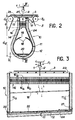
- an automatic fluid jet cutting device comprising a working nozzle 1 delivering a jet 2 of a fluid such as running water under a working pressure of, for example, between 3000 and 4000 bars.
- the jet 2 makes it possible to cut a sheet material at high speed 3 placed on a table or work surface 4 constituted by two flat parts and situated in the same plane of an endless flexible mat 5 mounted on rollers 6a to 6d and 7a to 7d. More precisely, the two flat parts of the flexible mat 5 constituting the working surface 4 are constituted by the parts of this mat situated, on the one hand, between the rollers 6a and 7a and, on the other hand, between the rollers 6d and 7d. As shown in fig. 1, the rollers 7a to 7d are arranged so that the flexible mat 5 forms a loop 8 opposite the working nozzle 1, this loop 8 connecting the two flat parts of the mat forming the working surface 4, defining between these two flat parts and opposite the nozzle 1 an opening 9.
- a mechanism (not shown) of any known type makes it possible to move the nozzle 1 in a transverse cutting direction relative to the device, along the opening 9. This displacement of the nozzle is shown diagrammatically by the arrow F, in FIG. 3.
- At least one of the rollers 6 and 7 carrying the flexible mat 5 is provided with drive means (not shown) also of a known type. The implementation of these means makes it possible to advance the mat 5 (arrow F2 in fig. 1) and the material 3 which it supports in a longitudinal direction relative to the device, that is to say perpendicularly to the cutting direction.
- the advance movement indicated by the arrow F 2 is carried out by the assembly constituted by the nozzle 1, the recovery system and the rollers 7 intimately linked, relative to the flexible mat 5 then fixed and keeping the previous configuration, the nozzle separately retaining its advance movement F 1 .
- a judicious combination of the movements F, and F 2 makes it possible to cut the material 3 along any cutting line determined in advance.
- a jet recovery system designated by the general reference 10 is housed in the loop 8.
- this working surface further comprises, in this opening 9 and above the neck of the chute, two flat and fixed plates 23 forming between them a slot 25 whose width is adapted according to the thickness of the material to be cut, so as to allow the passage of the jet 2.
- the jet recovery system 10 mainly comprises a metal chute 11 which extends transversely over the entire width of the apparatus, between two end partitions 11a, as shown in FIG. 3.
- the bottom of the chute 11 defines a gutter 12 having in section the shape of an arc of a circle.
- the chute 11 has a neck 15 of reduced width relative to the bottom 12 of the chute, and on which the plates 23 are fixed.
- the neck 15 is connected to the bottom 12 by a part 14 in the form of a divergent.
- the upper part of the neck 15 of the chute is empty over a certain distance d i from the material 3 to be cut.
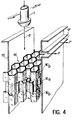
- the high-pressure fluid jet encounters a layer 16, of thickness e, of a metallic cellular material placed at the lower part of the neck 15 of the chute.
- the axis of the cells formed in the material 16 is parallel to the axis of the jet 2.
- the material 16 is composed of a fine mesh structure 16a sandwiched between two structures 16b with larger meshes. Given the pressure of the jets of fluid usually used, these jets do not cut metals, so that the energy of the jet is broken on the webs or walls of the cellular material.
- the vacuum device acting through the slot 17 can be adjusted in order to adjust the vacuum at the inlet of the neck of the chute according to the thickness of the material to be cut and according to the diameter of the nozzle used to perform the cut.
- the adjustment of the vacuum device communicating with the orifice 17 makes it possible in particular to increase the vacuum when the material to be cut is flexible.
- the slot 25 can thus be obstructed by this material, which limits the wetting of the top of the work surface.
- the depression has the effect of slightly pressing the first sheet or fold against the working surface at the level of the slot. The material to be cut is thus very little affected by cutting humidity.
- the jet travels a relatively large distance d 2 (fig. 2) relative to d i before encountering a liquid such as relatively cold running water 20 circulating in the bottom 12 from the chute.
- d 2 a relatively large distance relative to d i before encountering a liquid such as relatively cold running water 20 circulating in the bottom 12 from the chute.
- the circulation of water 20 in the bottom of the chute takes place between an inlet orifice 21 and an outlet orifice 22, under the effect of a slight inclination of the bottom 12 ( fig. 3). This inclination is small as well as the flow of water 20 which results therefrom, so that the height h of the water in the bottom of the chute is sufficient over the entire width of the device to ensure recovery anywhere. energy efficient of the jet.
- the internal wall of the chute is provided with two deflectors 18 having a section in an arc extending the wall of the bottom 12 of the chute.
- the deflectors 18 are arranged opposite one another and symmetrically with respect to the cutting plane generated by the axis of the nozzle 1 when the latter moves transversely to the device under the action of control means of a known type (not shown).
- the ends of the deflectors 18 define between them a slot 19 the width of which is just sufficient to allow the residual jet leaving the cellular material 16 to pass.
- the water 20 is put in circular motion in the space thus formed in the bottom of the chute upon the impact of the jet 2.
- the jet thus breaks up on the water put in rotation.
- the shape of the bottom of the chute and the deflectors makes it possible to avoid the rising of liquid which can alter, the quality of the cut material, in particular when it is a composite material. It also makes it possible to avoid the vibrations of the chute which may arise during the absorption of energy from the jet, due to its symmetry of construction.
- the circulation of water in the bottom of the chute makes it possible to evacuate the thermal energy of dissipation of the jet.
- the cutting apparatus makes it possible to absorb the mechanical energy of the jet, to dissipate the thermal energy originating from this absorption and to avoid liquid rising or splashing which could affect the quality of the cut material.
- a significant noise is produced.
- the reduction of this noise to an acceptable value for those present is obtained both thanks to the depression created in the upper part of the neck 15 through the orifice 17, thanks to the thickness e of the cellular material 16 and thanks at the height h of the water in the bottom of the chute.
- a layer 24 of sound-absorbing material such as a plastic material can be placed on the external wall of the chute.
- the energy recovery system 10 is perfectly suited to recovering a jet which is not never symmetrical due to the dispersion which it undergoes under the effect of the cutting movement which takes place as we have seen along a plane parallel to the direction of movement of the nozzle and perpendicular to the part to be cut.
- the structure of the device according to the invention is such that the first layer 16b of cellular material can be easily replaced when the latter is damaged.
- deterioration only occurs after a significant number of hours of cutting, due to the distance d i which separates the cellular material from the material to be cut.
- the device according to the invention makes it possible, if necessary, to recover the water used for cutting, to reinject it into the circuit of the device after filtration. .
Landscapes
- Life Sciences & Earth Sciences (AREA)
- Forests & Forestry (AREA)
- Engineering & Computer Science (AREA)
- Mechanical Engineering (AREA)
- Perforating, Stamping-Out Or Severing By Means Other Than Cutting (AREA)
Claims (8)
Applications Claiming Priority (2)
| Application Number | Priority Date | Filing Date | Title |
|---|---|---|---|
| FR8217473A FR2534516B1 (fr) | 1982-10-19 | 1982-10-19 | Appareil de decoupe par jet de fluide haute pression |
| FR8217473 | 1982-10-19 |
Publications (2)
| Publication Number | Publication Date |
|---|---|
| EP0107573A1 EP0107573A1 (de) | 1984-05-02 |
| EP0107573B1 true EP0107573B1 (de) | 1987-01-07 |
Family
ID=9278387
Family Applications (1)
| Application Number | Title | Priority Date | Filing Date |
|---|---|---|---|
| EP83401987A Expired EP0107573B1 (de) | 1982-10-19 | 1983-10-12 | Hochdruckflüssigkeitsstrahlschneidegerät |
Country Status (4)
| Country | Link |
|---|---|
| US (1) | US4501182A (de) |
| EP (1) | EP0107573B1 (de) |
| DE (1) | DE3368887D1 (de) |
| FR (1) | FR2534516B1 (de) |
Families Citing this family (35)
| Publication number | Priority date | Publication date | Assignee | Title |
|---|---|---|---|---|
| FR2553330B1 (fr) * | 1983-10-17 | 1988-04-22 | Aerospatiale | Machine de decoupe de matiere en bande par jet fluide haute pression |
| DE3339320C2 (de) * | 1983-10-29 | 1986-10-16 | VEGLA Vereinigte Glaswerke GmbH, 5100 Aachen | Verfahren zur Herstellung einer Verbundglasscheibe |
| US4669229A (en) * | 1985-07-10 | 1987-06-02 | Flow Systems, Inc. | Energy dissipating receptacle for high-velocity fluid jet |
| US4964244A (en) * | 1985-07-10 | 1990-10-23 | Flow Systems, Inc. | Energy dissipating receptacle for high-velocity fluid jet |
| KR930008692B1 (ko) * | 1986-02-20 | 1993-09-13 | 가와사끼 쥬고교 가부시기가이샤 | 어브레시브 워터 제트 절단방법 및 장치 |
| US4651476A (en) * | 1986-05-07 | 1987-03-24 | Flow Systems, Inc. | Compact receptacle with automatic feed for dissipating a high-velocity fluid jet |
| JPS6487199A (en) * | 1986-12-04 | 1989-03-31 | Ingersoll Rand Co | Receiving tank for spent liquid jet cutting liquid |
| JPS63232999A (ja) * | 1987-03-20 | 1988-09-28 | 北川工業株式会社 | 裁断装置 |
| US4787178A (en) * | 1987-04-13 | 1988-11-29 | Creative Glassworks International, Inc. | Fluid-jet cutting apparatus |
| US4790224A (en) * | 1987-08-20 | 1988-12-13 | Belcan Corporation | Travelling gap conveyor cutting method and apparatus |
| AU2399288A (en) * | 1987-11-30 | 1989-06-01 | Flow Systems Inc. | Energy-dissipating receptacle for high velocity fluid jet |
| FR2649925B1 (fr) * | 1989-07-18 | 1993-12-10 | Aerospatiale Ste Nationale Indle | Receptacle de jet de coupe pour une machine de decoupage par jet fluide |
| US5349788A (en) * | 1992-10-17 | 1994-09-27 | Saechsishe Werkzeug Und Sondermaschinen Gmbh | Apparatus for catching residual water jet in water jet cutting apparatus |
| DE4235090C2 (de) * | 1992-10-17 | 1998-09-03 | Saechsische Werkzeug Und Sonde | Flächenüberstreichender Liniencatcher (Fangeinrichtung) für eine Fluidstrahlschneidanlage |
| DE4235091C2 (de) * | 1992-10-17 | 2001-09-06 | Trumpf Sachsen Gmbh | Flüssigkeits- und Abrasivmittelzuführung für eine Fluidstrahlschneidanlage |
| FR2713130B1 (fr) * | 1993-12-06 | 1996-03-01 | Isin | Machine de découpe à dispositif de support de la matière en cours de découpe, notamment pour la découpe par jet d'eau. |
| US5831224A (en) * | 1995-04-07 | 1998-11-03 | Design Systems, Inc. | Noise reduction system for fluid cutting jets |
| IT1288656B1 (it) * | 1996-09-13 | 1998-09-23 | For El Base Di Vianello Fortun | Procedimento per il taglio di lastre di vetro e di lastre di vetro stratificato non blindato |
| IT1288675B1 (it) * | 1996-10-17 | 1998-09-23 | For El Base Di Vianello Fortun | Procedimento e macchina automatici per il taglio delle lastre di vetro stratificato e blindato |
| US5980372A (en) * | 1997-11-25 | 1999-11-09 | The Boeing Company | Compact catcher for abrasive waterjets |
| EP0983827A1 (de) * | 1998-08-31 | 2000-03-08 | Bystronic Laser AG | Wasserstrahl-Schneideanlage |
| GB9821024D0 (en) * | 1998-09-29 | 1998-11-18 | British Nuclear Fuels Plc | Improvements in and relating to fluid jet cutting |
| AT407742B (de) * | 1999-12-23 | 2001-05-25 | Lisec Peter | Verfahren und vorrichtung zum schneiden von glasscheiben |
| RU2170661C1 (ru) * | 2000-05-29 | 2001-07-20 | Орловский государственный технический университет | Установка для раскроя текстильных материалов сверхзвуковой струей жидкости |
| CA2370242A1 (en) | 2001-03-07 | 2002-09-07 | Dieter H. Hilker | Water jet edge cutter with integral trim chute |
| US20040043704A1 (en) * | 2002-08-30 | 2004-03-04 | Mark Saberton | Method and apparatus for high speed cutting |
| US20060180579A1 (en) * | 2005-02-11 | 2006-08-17 | Towa Intercon Technology, Inc. | Multidirectional cutting chuck |
| EP1926569B1 (de) * | 2005-09-06 | 2009-02-25 | Trumpf Werkzeugmaschinen GmbH + Co. KG | Vorrichtung zur aufnahme von plattenförmigen materialien für zumindest einen trennvorgang |
| ES2372727T3 (es) * | 2008-01-10 | 2012-01-25 | Alstom Technology Ltd | Dispositivo de recogida móvil para el chorro de agua de alta presión de una herramienta de chorro de agua así como procedimiento para hacerlo funcionar. |
| EP2636495A1 (de) * | 2012-03-08 | 2013-09-11 | Marel Iceland EHF | Schneidevorrichtung zum Schneiden von Lebensmittelartikeln, die auf einer Förderanlage mit mindestens einem Förderband befördert werden, sowie eine solche Vorrichtung enthaltendes System zur Behandlung von Nahrungsmitteln |
| NL2011299C2 (en) * | 2013-08-13 | 2015-02-16 | Bruijne Delden Holding B V De | Transport apparatus and cutting device. |
| ITVE20130063A1 (it) * | 2013-12-02 | 2015-06-03 | Dallan Spa | Apparecchiatura per la movimentazione di un nastro o foglio di lamiera sottoposto a taglio laser.- |
| DE102015003690B4 (de) * | 2015-03-24 | 2017-01-12 | Capex Invest GmbH | Wasserstrahlschneidevorrichtung und Schneideverfahren |
| ES2734498B2 (es) * | 2018-05-07 | 2021-12-16 | Goiti S Coop | Maquina para corte de laminas por proyeccion de fluidos |
| US11518058B2 (en) * | 2019-12-16 | 2022-12-06 | Nienstedt Gmbh | Collecting and discharging device for the cutting jet of a liquid cutting system |
Family Cites Families (8)
| Publication number | Priority date | Publication date | Assignee | Title |
|---|---|---|---|---|
| FR567908A (fr) * | 1923-06-27 | 1924-03-12 | Pare-boue circulaire amovible pour bandages pneumatiques | |
| NL6406916A (de) * | 1964-06-17 | 1965-12-20 | ||
| US3730040A (en) * | 1971-08-17 | 1973-05-01 | Bendix Corp | Energy absorber for high pressure fluid jets |
| US3877334A (en) * | 1973-11-23 | 1975-04-15 | Gerber Garment Technology Inc | Method and apparatus for cutting sheet material with a fluid jet |
| US4137804A (en) * | 1974-07-12 | 1979-02-06 | Gerber Garment Technology, Inc. | Fluid cutting jet receiver |
| US4092889A (en) * | 1975-04-09 | 1978-06-06 | The British Hydromechanics Research Association | Slotted worktable |
| US4112797A (en) * | 1977-10-07 | 1978-09-12 | Gerber Garment Technology, Inc. | Fluid jet cutting apparatus |
| US4312254A (en) * | 1977-10-07 | 1982-01-26 | Gerber Garment Technology, Inc. | Fluid jet apparatus for cutting sheet material |
-
1982
- 1982-10-19 FR FR8217473A patent/FR2534516B1/fr not_active Expired
-
1983
- 1983-10-12 EP EP83401987A patent/EP0107573B1/de not_active Expired
- 1983-10-12 US US06/541,137 patent/US4501182A/en not_active Expired - Lifetime
- 1983-10-12 DE DE8383401987T patent/DE3368887D1/de not_active Expired
Also Published As
| Publication number | Publication date |
|---|---|
| FR2534516A1 (fr) | 1984-04-20 |
| DE3368887D1 (en) | 1987-02-12 |
| FR2534516B1 (fr) | 1986-08-08 |
| EP0107573A1 (de) | 1984-05-02 |
| US4501182A (en) | 1985-02-26 |
Similar Documents
| Publication | Publication Date | Title |
|---|---|---|
| EP0107573B1 (de) | Hochdruckflüssigkeitsstrahlschneidegerät | |
| FR2570636A1 (fr) | Appareil et procede pour supporter une feuille dans une installation de decoupe par jet de fluide | |
| EP0006385B1 (de) | Apparate mit biegsamen Paletten zum Einsammeln schwimmender Materialien | |
| FR2528994A1 (fr) | Positionneur de recepteur de jet de fluide, pour un appareil a decouper des matieres en feuilles au moyen de jets de fluide de coupe | |
| EP1380027A1 (de) | Lärmdämpfungsplatte mit widerstandschicht mit verstärktem strukturteil | |
| FR2536432A1 (fr) | Procede pour la fabrication d'etoffes non tissees portant des motifs en creux ou en relief, et etoffes non tissees ainsi obtenues | |
| EP2571823A1 (de) | Alveoläre biegeform | |
| EP0193075A1 (de) | Verfahren zum Endlosmachen eines mehrlagigen Entwässerungsbandes, insbesondere eines Papiermachernassfilzes | |
| EP1205604B1 (de) | Verfahren und Vorrichtung zum Aufnehmen einer Schwimmschicht von einer Flüssigkeit | |
| EP0319416B1 (de) | Verfahren und Vorrichtung zum Beschichten einer Glasscherbe mit einer weichen Kunststoffolie | |
| WO2021260320A1 (fr) | Convoyeur de coupe a aspiration pour une machine de coupe automatique par lame de materiaux en feuilles | |
| FR2570637A1 (fr) | Procede de decoupe de verre de diverses epaisseurs | |
| FR2726288A1 (fr) | Dispositif a lame d'air pour le reglage de l'epaisseur d'un depot | |
| FR2719610A1 (fr) | Dispositif de récupération de produits polluants répandus sur l'eau ou sur le sol. | |
| WO2006134271A1 (fr) | Procede de realisation d'un renfort pour materiau composite a profil de resistance variable, renfort obtenu | |
| WO1980000721A1 (fr) | Engin de prelevement selectif d'une couche de liquide leger a la surface d'une nappe d'eau | |
| WO1995015837A1 (fr) | Machine de decoupe a dispositif de support de la matiere en cours de decoupe, notamment pour la decoupe par jet d'eau | |
| EP0079824A1 (de) | Markieren von zusammengesetzten durch Glasfäden bewehrten Gipsprodukten | |
| WO1999040993A1 (fr) | Separateur pour melange triphasique destine a etre utilise sous le niveau de la mer | |
| BE1009193A3 (fr) | Procede destine a neutraliser des inclusions chaudes situees dans une nappe de laine minerale ainsi que dispositif de mise en oeuvre dudit procede. | |
| FR2622140A1 (fr) | Dispositif pour decouper des materiaux | |
| CA1029908A (en) | Installation for the continuous manufacture of synthetic material panels | |
| EP1573147A1 (de) | Platte für thermoakustische wandisolierung | |
| WO2007057609A1 (fr) | Machine de coupe automatique de materiaux en feuille a caisson de depression bombe | |
| EP0363282B1 (de) | Verwendung einer Düse mit convergent-divergenten Profil in einer Ausstossvorrichtung eines Wurzelschneiders |
Legal Events
| Date | Code | Title | Description |
|---|---|---|---|
| PUAI | Public reference made under article 153(3) epc to a published international application that has entered the european phase |
Free format text: ORIGINAL CODE: 0009012 |
|
| AK | Designated contracting states |
Designated state(s): DE GB IT NL |
|
| 17P | Request for examination filed |
Effective date: 19841015 |
|
| GRAA | (expected) grant |
Free format text: ORIGINAL CODE: 0009210 |
|
| AK | Designated contracting states |
Kind code of ref document: B1 Designated state(s): DE GB IT NL |
|
| ITF | It: translation for a ep patent filed | ||
| REF | Corresponds to: |
Ref document number: 3368887 Country of ref document: DE Date of ref document: 19870212 |
|
| PLBE | No opposition filed within time limit |
Free format text: ORIGINAL CODE: 0009261 |
|
| STAA | Information on the status of an ep patent application or granted ep patent |
Free format text: STATUS: NO OPPOSITION FILED WITHIN TIME LIMIT |
|
| 26N | No opposition filed | ||
| ITTA | It: last paid annual fee | ||
| REG | Reference to a national code |
Ref country code: GB Ref legal event code: IF02 |
|
| PGFP | Annual fee paid to national office [announced via postgrant information from national office to epo] |
Ref country code: GB Payment date: 20021009 Year of fee payment: 20 |
|
| PGFP | Annual fee paid to national office [announced via postgrant information from national office to epo] |
Ref country code: DE Payment date: 20021023 Year of fee payment: 20 |
|
| PGFP | Annual fee paid to national office [announced via postgrant information from national office to epo] |
Ref country code: NL Payment date: 20021031 Year of fee payment: 20 |
|
| PG25 | Lapsed in a contracting state [announced via postgrant information from national office to epo] |
Ref country code: GB Free format text: LAPSE BECAUSE OF EXPIRATION OF PROTECTION Effective date: 20031011 |
|
| PG25 | Lapsed in a contracting state [announced via postgrant information from national office to epo] |
Ref country code: NL Free format text: LAPSE BECAUSE OF EXPIRATION OF PROTECTION Effective date: 20031012 |
|
| REG | Reference to a national code |
Ref country code: GB Ref legal event code: PE20 |
|
| NLV7 | Nl: ceased due to reaching the maximum lifetime of a patent |
Effective date: 20031012 |