EP0106661A2 - Verfahren und Gerät zum Nachlaufsteuern eines Plattenlaufwerks - Google Patents
Verfahren und Gerät zum Nachlaufsteuern eines Plattenlaufwerks Download PDFInfo
- Publication number
- EP0106661A2 EP0106661A2 EP83306177A EP83306177A EP0106661A2 EP 0106661 A2 EP0106661 A2 EP 0106661A2 EP 83306177 A EP83306177 A EP 83306177A EP 83306177 A EP83306177 A EP 83306177A EP 0106661 A2 EP0106661 A2 EP 0106661A2
- Authority
- EP
- European Patent Office
- Prior art keywords
- track
- disk
- tracks
- offset
- diagnostic
- Prior art date
- Legal status (The legal status is an assumption and is not a legal conclusion. Google has not performed a legal analysis and makes no representation as to the accuracy of the status listed.)
- Withdrawn
Links
- 238000000034 method Methods 0.000 title claims abstract description 13
- 238000012360 testing method Methods 0.000 claims abstract description 24
- 230000007246 mechanism Effects 0.000 claims abstract description 13
- 230000004044 response Effects 0.000 claims abstract description 3
- 230000000750 progressive effect Effects 0.000 claims description 45
- 230000000977 initiatory effect Effects 0.000 claims 1
- 238000005259 measurement Methods 0.000 abstract description 5
- 230000007704 transition Effects 0.000 abstract 1
- 238000010586 diagram Methods 0.000 description 8
- 230000006870 function Effects 0.000 description 2
- 238000011056 performance test Methods 0.000 description 2
- 238000010276 construction Methods 0.000 description 1
- 238000013500 data storage Methods 0.000 description 1
- 230000000694 effects Effects 0.000 description 1
- 230000007613 environmental effect Effects 0.000 description 1
- 238000012986 modification Methods 0.000 description 1
- 230000004048 modification Effects 0.000 description 1
- 238000012544 monitoring process Methods 0.000 description 1
- 230000002093 peripheral effect Effects 0.000 description 1
- 229920000728 polyester Polymers 0.000 description 1
- 230000009467 reduction Effects 0.000 description 1
- 238000009987 spinning Methods 0.000 description 1
- 239000000758 substrate Substances 0.000 description 1
- 238000012549 training Methods 0.000 description 1
Images
Classifications
-
- G—PHYSICS
- G11—INFORMATION STORAGE
- G11B—INFORMATION STORAGE BASED ON RELATIVE MOVEMENT BETWEEN RECORD CARRIER AND TRANSDUCER
- G11B5/00—Recording by magnetisation or demagnetisation of a record carrier; Reproducing by magnetic means; Record carriers therefor
- G11B5/012—Recording on, or reproducing or erasing from, magnetic disks
- G11B5/016—Recording on, or reproducing or erasing from, magnetic disks using magnetic foils
-
- G—PHYSICS
- G11—INFORMATION STORAGE
- G11B—INFORMATION STORAGE BASED ON RELATIVE MOVEMENT BETWEEN RECORD CARRIER AND TRANSDUCER
- G11B23/00—Record carriers not specific to the method of recording or reproducing; Accessories, e.g. containers, specially adapted for co-operation with the recording or reproducing apparatus ; Intermediate mediums; Apparatus or processes specially adapted for their manufacture
- G11B23/30—Record carriers not specific to the method of recording or reproducing; Accessories, e.g. containers, specially adapted for co-operation with the recording or reproducing apparatus ; Intermediate mediums; Apparatus or processes specially adapted for their manufacture with provision for auxiliary signals
- G11B23/36—Signals on record carriers or on containers and recorded by the same method as the main recording
-
- G—PHYSICS
- G11—INFORMATION STORAGE
- G11B—INFORMATION STORAGE BASED ON RELATIVE MOVEMENT BETWEEN RECORD CARRIER AND TRANSDUCER
- G11B27/00—Editing; Indexing; Addressing; Timing or synchronising; Monitoring; Measuring tape travel
- G11B27/10—Indexing; Addressing; Timing or synchronising; Measuring tape travel
- G11B27/19—Indexing; Addressing; Timing or synchronising; Measuring tape travel by using information detectable on the record carrier
- G11B27/28—Indexing; Addressing; Timing or synchronising; Measuring tape travel by using information detectable on the record carrier by using information signals recorded by the same method as the main recording
- G11B27/32—Indexing; Addressing; Timing or synchronising; Measuring tape travel by using information detectable on the record carrier by using information signals recorded by the same method as the main recording on separate auxiliary tracks of the same or an auxiliary record carrier
-
- G—PHYSICS
- G11—INFORMATION STORAGE
- G11B—INFORMATION STORAGE BASED ON RELATIVE MOVEMENT BETWEEN RECORD CARRIER AND TRANSDUCER
- G11B5/00—Recording by magnetisation or demagnetisation of a record carrier; Reproducing by magnetic means; Record carriers therefor
- G11B5/48—Disposition or mounting of heads or head supports relative to record carriers ; arrangements of heads, e.g. for scanning the record carrier to increase the relative speed
- G11B5/58—Disposition or mounting of heads or head supports relative to record carriers ; arrangements of heads, e.g. for scanning the record carrier to increase the relative speed with provision for moving the head for the purpose of maintaining alignment of the head relative to the record carrier during transducing operation, e.g. to compensate for surface irregularities of the latter or for track following
- G11B5/596—Disposition or mounting of heads or head supports relative to record carriers ; arrangements of heads, e.g. for scanning the record carrier to increase the relative speed with provision for moving the head for the purpose of maintaining alignment of the head relative to the record carrier during transducing operation, e.g. to compensate for surface irregularities of the latter or for track following for track following on disks
- G11B5/59627—Aligning for runout, eccentricity or offset compensation
Definitions
- This invention relates to the field of disk drives designed for use with diskettes (floppy disks), and particularly to techniques for checking the alignment and performance of such disk drives.
- Disk drives are known which are designed for use with flexible recording media popularly known as diskettes or floppy disks.
- such disk drives include a motor driven drive spindle and associated clamping mechanism for receiving and rotating a floppy disk at a predetermined constant speed, a transducer positioning assembly for radially positioning a read/ write transducer in response to track position commands, and electronic circuitry for operating the motor, the transducer positioning mechanism and also for furnishing data to and reading data from the floppy disk.
- Some disk drives are designed with only one read/write transducer,,while others are designed with a pair of such transducers for enabling data to be written on to and read from both sides of the floppy disk.
- Data is organized on a floppy disk using a series of ideally concentric tracks, with each track being divided into a plurality of sectors formatted in a predetermined standard manner, such as an IBM 3740 format or an IBM System 34 format.
- the format specifies the sequence and location of certain types of information, such as track number, sector number, data field, etc.
- Floppy disk recording capacity is also specified as the number of tracks per inch, with forty-eight tracks per inch and ninety-six tracks per inch being popular recording densities, the former requiring a track width in the radial direction of 12 mils., the latter requiring a track width of 6 mils.
- the actual data is recorded onto a track using conventional magnetic recording techniques for binary data.
- the positioner mechanism should ideally locate the transducer symmetrically over the center line of the circular data track, with the transducer gap perpendicular to the track center line (zero Azimuth).
- the transducer is moved from track to track, such movement should ideally be precisely along a radius of the diskette and not skewed at an angle to the radius (zero skew).
- the transducer is moved to the same track . radially inwardly and radially outwardly, the final position over the track should be the same (zero hysteresis).
- the angular rotational position of the floppy disk must be precisely known to insure that data is stored or retrieved at a particular location in a given sector of a particular track: for this reason, each floppy disk is provided with an index hole as a zero angle reference, and the passage of this hole past an index transducer mounted in the disk drive acts as a zero reference point. Misalignment of the index transducer in the disk drive can cause erroneous data storage and retrieval. In addition, since the data is recorded in ideally concentric tracks on the floppy disk, any eccentricity of the disk drive spindle/ clamp assembly will cause read and write errors.
- An alternate offset track is usually arranged as a sector identification number followed by a sector data field offset either radially inwardly or radially outwardly by a predetermined distance.
- the offset sector data field is followed by the next sector identification number and another sector data field offset in the opposite radial direction by the same predetermined distance. The sequence continues around the entire track.
- a progressively offset track is similar to an alternate offset track with the exception that the sector data fields are progressively offset from track center line by an increasing value: thus, for example, in one such implementation, the first two sector data fields are recorded directly on center, the sector three data field is recorded with a four milli-inch offset in the direction of the center of the disk, the sector four data field is recorded with a four milli-inch offset in the direction of the outer periphery of the floppy disk, the sector five data field is recorded with an offset of five milliinches towards the hub, the sector six data field is recorded with a five milli-inch offset in the peripheral direction, etc.
- the Azimuth track is recorded using the sector ID followed by the sector data field sequence, but with each data field being recorded at an Azimuthal angle with respect to the track center line, with alternate data fields being recorded at positive and negative angles.
- the alternate offset track has been employed to check the eccentricity of the disk drive spindle/clamp assembly by determining the readability of a sector, which is influenced by the reduction in amplitude due to the offset: for a perfectly concentric track, the amplitudes should be equal, while for an eccentric track the amplitudes will vary.
- a single alternate offset track has been used for checking eccentricity.
- the progressively offset tracks have been used to measure the radial alignment and hysteresis of the disk drive positioner mechanism: the former is checked by monitoring the electrical output signal to determine the point at which the sector data field is so far displaced from the track center line that the signals fall below the acceptable readability level.
- the first two sectors for which a read failure is observed should be equally displaced on either side of track center line, while a misaligned disk drive is signified by a nonsymmetrical maximum read pattern.
- the latter is checked by first positioning the transducer to the progressive alignment track by approaching the track along a first direction, followed by positioning the transducer to the same track from the opposite radial direction: the difference in the two radial alignments signifies the drive hysteresis error.
- the Azimuth track is used to check the head Azimuth alignment in a manner similar to the use of the progressive offset tracks to check radial alignment: for a perfectly aligned drive, the read/write transducer will fail to read sectors that are equally rotated clockwise and counterclockwise, while a misaligned head will produce nonsymmetrical maximum read patterns.
- timing tracks consisting of circumferential data bits precisely placed on the track relative to the photo index pulse to measure alignment of the index transducer and rotational speed.
- Diagnostic diskettes of the above type have been found useful in measuring disk drive alignment and performance for a number of reasons. Firstly, the variety of tests noted above can be performed in a relatively short period of time, on the order of five minutes, under actual disk drive operating conditions. Since the tests are performed using software routines incorporated into the associated computer with which the disk drive under test is actually employed, no special equipment is required, and thus no special technical training is necessary (provided that the user understands the operation of his own computer). Further, since the diagnostic diskette has the same physical characteristics as an ordinary user diskette, any errors due to unusual environmental temperature and humidity conditions in the environment of the disk drive will be exhibited by errors in the alignment performance.
- the invention comprises a diagnostic apparatus and method which affords all of the advantages noted above for the known diagnostic diskette while at the same time providing additional advantages enabling a more accurate analysis of the disk drive alignment and performance characteristics.
- the invention comprises a digital prerecorded diagnostic diskette having a plurality of alternate offset, progressive offset and timing tracks each arranged in a predetermined configuration to provide improved radial alignment, index timing, skew and eccentricity tests.
- the progressive offset tracks include an inner track, an outer track and at least one intermediate track in which the data sector field offset distances guarantee a read failure at the upper end of the offset range in all but the worst alignment conditions.
- the radial position of the plurality of progressive offset tracks is selected to ensure that, for disk drives employing a multiphase stepper motor, the radial alignment characteristic is tested for each phase of the stepper motor.
- the alternate offset tracks provide an improved eccentricity alignment test by using offsets of different values for different tracks, with the magnitude of the offset being greater for inner tracks than for outer tracks.
- An improved index timing test is afforded by an index timing track which provides a first sector identification a fixed distance after the index hole. By computing the time period between the generation of the index pulse and the reading of the first sector identification byte, the positional accuracy of the index transducer can be exactly measured.
- An improved skew test is afforded by providing both an inner and an outer index- timing track, and by simply performing an index timing test on the inner track and outer track, and noting differences therebetween.
- an inner and an outer timing track each having a sector ID written at predetermined time increments in each track and beginning that same predetermined time period after the index position provides a head-media compliance test for measuring the time required for valid data to first be generated (head-load time). The speed of the rotation of the diskette is measured by noting the average time between generation of-successive index pulses.
- transducer positioner linearity is checked by using the progressive offset tracks distributed across the entire radial surface of the diskette and the resulting electrical output signals are compared to determine the deviation therebetween.
- positional accuracy of each of the phases of a multiphase stepper motor are specifically checked by operating the transducer positioning mechanism to position the transducer over each of the progressive offset tracks and noting the sector ID number of the first pair of read failures.
- the existence of eccentricity of the drive spindle/clamp assembly can be determined and different degrees of eccentricity can be tested by using different ones of the alternate offset tracks each alternate offset track having a different amount of offset.
- the index timing of the disk drive can be accurately checked by noting the elapsed time between generation of the index pulse and reading of the first sector identification.
- the skew of the transducer head is measured by performing the index timing test on the inner and outer index timing tracks and comparing the two time values.
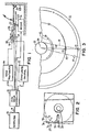
- Fig. 1 is a schematic block diagram illustrating the major components of a computer system incorporating a disk drive for a floppy disk.
- a computer.10 generates address, data and.control signals which are communicated over one or more data buses 11 to a disk drive controller 12.
- the disk drive controller is coupled to a head positioner unit 14, a read/write control unit 15, a motor 16, and an index pulse generator consisting of a light source 18 and a photo transducer 19:
- head positioner 14 is mechanically coupled to a carrier member 21 on which the read/write transducer 22 is mounted for linear motion radially inwardly and outwardly of a disk 25.
- Disk 25 is removably mounted on a motor spindle 26 for rotation in a plane perpendicular to the page of Fig. 1, the disk 25 being held on the spindle by means of a clamp assembly 27 pivotally mounted to a fixed reference 28 and tensioned by a bias mechanism 29.
- Transducer 22 receives read/write control signals from control unit 15 and is capable of recording data digitally on the recording surface of disk 25 and reading data from the recording surface of disk 25.
- Index transducer 19 provides an index pulse per revolution of disk 25 which is used to provide an angular positional starting reference.
- Fig. 2 illustrates a typical diskette 25, and as seen in this Fig. the diskette includes an outer jacket 31 containing an inner annular recording element 3 2 typically consisting of a pair of magnetic recording surfaces formed on a flexible polyester substrate.
- Jacket 31 has an elongated aperture 33 for enabling transducer 22 to gain access to the recording surface, .and a small circular aperture 35 positioned for alignment with a corresponding aperture 36 formed in the recording disk 32 once per revolution to provide an unblocked light path for source 18 and index transducer 19.
- Fig. 3 is a partial plan view illustrating difference types of misalignment which can occur with a disk drive system of the type shown in Fig. 1 when a diskette of the type shown in Fig. 2 is inserted.
- Fig. which is representative of ⁇ a five inch diskette arranged for a recording density of ninety six tracks per inch
- data is digitally recorded ideally along a plurality of closely packed concentric circular tracks, only three of which are illustrated by showing the center lines of the tracks (track 0, track. 32 and track 79).
- a first type of misalignment which can occur is termed radial misalignment and three different conditions of radial alignment are illustrated: with transducer 22 positioned as shown on track 32, the transducer is perfectly centered radially with respect to the track center line; on track 0, transducer 22 is radially misaligned in the radial outward direction (negative offset); while on track 79 transducer 22 is radially misaligned in the radially inward direction (positive offset).
- Dashed line 41 illustrates a condition of skew: dashed line 41 represents the linear path taken by transducer 22 when translated by a carrier member 21 whose path is skewed with respect to the radius 40 of the diskette. As illustrated by broken line 41, the transducer alignment progressively deviates from the radius 40 as the transducer 22 is moved in the radially inward direction.
- Phantom segment 43 illustrates eccentricity: ideally, the geometrical center of the diskette 32 coincides with the central axis of the spindle 26, and both the spindle aperture - 37 of diskette 32 and the circumference of spindle 26 are perfectly circular. In reality, this is not always the case and the circular tracks recorded on a diskette can be radially offset with respect to the axis of rotation of the spindle 26, so that the circular tracks deviate from the perfect concentric circular path as illustrated by phantom segment 43.
- Phantom line 45 illustrates index timing misalignment which can occur if the index transducer 19 is misaligned with respect to the predetermined home position of the jacket aperture 35 (it being remembered that this member is fixed in position when inserted into the drive unit).
- the angle subtended between phantom 45 and radius 40 illustrates the index timing error.
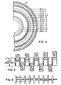
- Fig. 4 is a partial schematic plan view of a diagnostic diskette fabricated according to the teachings of the invention.
- the diskette 50 is provided with a number of prerecorded tracks which are precisely positioned on the surface of the diskette and which contain special alignment information to be used for the several tests described below.
- the numbered tracks shown in Fig. 4 follow the following format:
- the above format is specifically provided for a five inch diskette having a 96 tracks per inch recording density.
- the individual track formats are as follows:
- PROGRESSIVE OFFSET
- Tracks are written with track and sector ID fields on track centerline. Data fields are radially displaced from the track centerline as shown below. Positive value indicates an offset toward the spindle, negative value indicates away from the spindle.
- First sector ID header (#1) occurs at 1 ms after photo index and at 1 ms increments thereafter.
- Sectors 1 and 2 of all recorded tracks except 6 the timing tracks are recorded with the diskette revision, serial number, part number, format type, tracks per . inch, bytes per sector and side identifier. Also, there is a block identifying tracklocations and functions along with the range and increment of each track. This information appears as follows:
- Fig. 5 illustrates in schematic form a linearized version of the first nine sectors of a progressive offset track, such as track 0, track 6, etc.
- each sector ID is followed by a fixed block of sector data, with each sector data block being progressively offset in alternating -positive and negative directions.
- the sector data block for sector number 13 will be completely outside the range of a perfectly aligned read/write transducer.
- the effect on the output signal of the progressive misalignment is illustrated in Fig. 6 for the first nine sectors and following data blocks for a perfectly aligned transducer.
- read failures should occur prior to reaching the sixteenth sector data block.
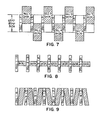
- Fig. 7 is a schematic diagram illustrating a highly linearized version of an alternate offset track, such as track 44. As seen in this Fig., each sector ID is followed by a block of data offset by a predetermined value from the track center line.
- Fig. 8 illustrates the play back signal received from a perfectly aligned transducer from an alternate offset track such as that shown in Fig. 7.
- Another example of a digitally prerecorded diagnostic diskette suitable for use in a five inch diskette with a track density of one hundred tracks per inch is as follows:
- PROGRESSIVE OFFSET
- Tracks are written with track and sector ID fields on track centerline. Data fields are radially displaced from the track centerline as shown below. Positive value indicates an offset toward the spindle, negative value indicates away from the spindle.
- First sector ID header (#1) occurs at 1 ms after photo index and at 1 ms increments thereafter.
- a comparison of the two above formats illustrates the similarities and differences between a five inch diskette with ninety six tracks per inch and a five inch diskette with one hundred tracks per inch.
- the value of the progressive offsets and the three alternate offsets are identical, and both diskettes have the same number of prerecorded tracks.
- the central and inner track numbers are different and the innermost progressive offset and timing tracks are reversed in order (i.e. in the case of the ninety six tracks per inch diskette the innermost progressive offset track is recorded outwardly of the inner most timing track, while in the one hundred tracks per inch version that order is reversed).
- PROGRESSIVE OFFSET
- Tracks are written with track and sector ID fields on track centerline. Data fields are radially displaced from the track centerline as shown below. Positive value indicates an offset toward the spindle, negative value indicates away from the spindle.
- First sector ID header (#1) occurs at 1 ms after photo index and at 1 ms incrments thereafter.
- Track and sector ID fields are written at zero azimuth.
- Data fields are written with the head azimuth angle shown below.
- Sectors 1 and 2 of all recorded tracks except the timing tracks are recorded with the diskette revision, serial number, part number, format type, tracks per inch, bytes per sector and side identifier. Also, there is a block identifying track locations and functions along with the range and increment of each track. This information appears as follows:
- PROGRESSIVE OFFSET
- Tracks are written with track and sector ID fields on tra ⁇ centerline. Data fields are radially displaced from the track centerline as shown below. Positive value indicateg an offset toward the spindle, negative value indicates awa from the spindle.
- First sector ID header (#1) occurs at 1 ms after photo index and at 1 ms increments thereafter.
- Track and sector ID fields are written at zero azimuth.
- Data fields are written with the head azimuth angle shown below.
- FIG. 9 shows the first eight sectors of an Azimuth rotation track, which is seen to include a series of sector ID blocks interspersed with data blocks, with successive pairs of data blocks being recorded at the same Azimuthal angle with respect to the track center line, and with the Azimuthal angle of each pair increasing along the track.
- This track is used to determine the Azimuthal read margins of the recording gap of the transducer 22 with respect to the track center line. If the head is perfectly aligned asamu- thally, the first pair of read failures should occur at the same angle in the positive and negative directions.
- a comparison of the two forty eight track per inch prerecorded diskettes shows the similarities and differences therebetween.
- the two formats use the same number of prerecorded tracks, and the same number of progressive offset tracks, index format tracks, timing tracks, alternate offset tracks and a single Azimuth rotation track combined with an index format track. With the exception of the first three tracks, the track numbers are different and the sequence of tracks varies in the manner indicated.
- the specific track location and sequence of the different types of prerecorded digital tracks are selected on the basis of a number of criteria. Firstly, since radial alignment should be checked entirely across the recording surface of the disk, progressive offset tracks should be provided at least near the innermost track, the outermost track and a center track. Further, to ensure that each phase of a stepper motor shaft position will be tested for both three phase and four phase stepper motors, six progressive offset tracks are employed, with the specific locations selected to accomplish this purpose. Each diskette should be provided with a separate timing track near the outermost track and the innermost track in order to test head-media compliance at both extreme transducer position. Similarly, the index timing tracks are provided adjacent the innermost and outermost track locations in order to provide a skew measurement reference.
- the amount of the progressive offset is selected to match the head width for which the disk drive is designed so that a read failure is guaranteed at some point along each progressive offset track. For example, for the forty eight track per inch versions, which are designed for use with 12 mil heads, the progressive offset begins at 6 mils and extends to 13 mils, representing a transducer completely off track.
- the alternate offset track values are selected to. providing three different levels of criteria for judging the eccentricity of the drive.
- the diagnostic diskettes are used in conjunction with a diagnostic program loaded into computer 10 to perform the various alignment and performance tests of the disk drive.
- the alternate offset tracks are used to measure the eccentricity of the drive. For a properly aligned drive all sectors around a given track should be read equally, and this should be true for all three offset tracks. This test ensures that the drive spindle is spinning properly and further that the disk is centered on the spindle.
- the index timing tracks each incorporate sector identification.information precisely written so as to be spaced at a multiple of an exact time period from the leading edge of the index pulse. For a double density MFM recorded eight inch disk, this time period is approximately 320 microseconds; while for a single density FM recorded eight inch disk the time period is 640 microseconds.
- a timer in the computer is started and stopped after the first sector ID has been read. The time value achieved by the counter provides an indication of the alignment of the index transducer 19.
- the index timing tracks are also used to measure positioner skew by performing the index timing test on the outer most track and the inner most track and comparing the two values obtained.
- Head positioner linearity is measured using the progressive offset tracks: each progressive offset track is read and the read failures are used to indicate the linearity.
- Head load time is measured by means of the two timing tracks provided on each diskette. Beginning with the generation of a read command, the number of ID blocks written at approximately one millisecond increments on a timing track are scanned until a valid read is obtained from the timing track. The ID number of the first valid read directly indicates the time required by the drive to achieve proper head loading. If desired, a timer may be used to provide a digital indication of the head load time.
- either timing track may be used to measure the spindle speed.
- Azimuthal margin rotation is measured (in the case of forty eight tracks per inch disk drives) using the Azimuthal rotation track provided on each diskette. As noted above, a read failure should be obtained for a pair of data blocks recorded at the positive and nega. tive values of the same Azimuthal angle.
- the invention affords a degree of flexibility and a testing accuracy absent from the known diagnostic diskettes described supra. For example, by providing progressive offsets sufficiently great to guarantee read failures when performing a radial alignment test, the user is assured that even a disk drive with superior performance characteristics and perfect alignment can have its maximum margins determined. Further, the progressive offset tracks serve the additional purpose of testing the hysteresis performance of the transducer positioning mechanism. In addition, by careful selection of the number and location of the progressive offset tracks, the alignment of all phases of multiphase stepping motors can be checked regardless of whether the motor is a three phase or a four phase motor.
- the timing track has been found to provide a highly accurate measurement of the head-load time; and the use of an inner and outer pair of identical index timing tracks provides a measurement of the index transducer alignment and also enables a different alignment measurement to be obtained by simply repeating the same test twice using the different tracks.
- a separate set of eccentricity tracks i.e. the three alternate offset tracks
- different degrees of spindle eccentricity can be determined in a relatively simple manner.
Landscapes
- Adjustment Of The Magnetic Head Position Track Following On Tapes (AREA)
- Moving Of The Head To Find And Align With The Track (AREA)
- Signal Processing For Digital Recording And Reproducing (AREA)
Applications Claiming Priority (2)
| Application Number | Priority Date | Filing Date | Title |
|---|---|---|---|
| US06/433,950 US4513331A (en) | 1982-10-12 | 1982-10-12 | Method and apparatus for disk drive alignment |
| US433950 | 1982-10-12 |
Publications (2)
| Publication Number | Publication Date |
|---|---|
| EP0106661A2 true EP0106661A2 (de) | 1984-04-25 |
| EP0106661A3 EP0106661A3 (de) | 1985-08-07 |
Family
ID=23722218
Family Applications (1)
| Application Number | Title | Priority Date | Filing Date |
|---|---|---|---|
| EP83306177A Withdrawn EP0106661A3 (de) | 1982-10-12 | 1983-10-12 | Verfahren und Gerät zum Nachlaufsteuern eines Plattenlaufwerks |
Country Status (4)
| Country | Link |
|---|---|
| US (1) | US4513331A (de) |
| EP (1) | EP0106661A3 (de) |
| JP (1) | JPS59132465A (de) |
| CA (1) | CA1205189A (de) |
Cited By (7)
| Publication number | Priority date | Publication date | Assignee | Title |
|---|---|---|---|---|
| EP0162407A1 (de) * | 1984-05-18 | 1985-11-27 | BASF Aktiengesellschaft | Verfahren und Anordnung zur Fehlersignalermittlung in einem Magnetplattenspeicher und Testmagnetplatte dafür |
| EP0162689A2 (de) * | 1984-05-21 | 1985-11-27 | Sony Corporation | Magnetische Plattenwiedergabevorrichtung |
| EP0179299A2 (de) * | 1984-10-25 | 1986-04-30 | Verbatim Corporation | Justierplatte und Verfahren zu ihrer Herstellung |
| GB2174530A (en) * | 1985-03-29 | 1986-11-05 | Canon Kk | Optical record medium (card) recording/reproduction |
| EP0310250A2 (de) * | 1987-10-02 | 1989-04-05 | International Business Machines Corporation | Gerät für eine entfernbare Platte mit Regelung der Position der Rotation |
| EP0347881A2 (de) * | 1988-06-21 | 1989-12-27 | Matsushita Electric Industrial Co., Ltd. | Speichermedium-Verwaltungssystem |
| EP0562758A2 (de) * | 1992-03-25 | 1993-09-29 | International Business Machines Corporation | Positionsidentifizierung und Fehlerbehandlung in einer Datenaufnahmeplatteneinheit |
Families Citing this family (14)
| Publication number | Priority date | Publication date | Assignee | Title |
|---|---|---|---|---|
| US4562494A (en) * | 1983-04-07 | 1985-12-31 | Verbatim Corporation | Disk drive alignment analyzer |
| US4694359A (en) * | 1985-02-08 | 1987-09-15 | Nec Corporation | Diagnostic disk for checking the head alignment of magnetic disk drives |
| JPS62175974A (ja) * | 1986-01-29 | 1987-08-01 | Hitachi Ltd | 磁気ヘツド調整方法 |
| US4992893A (en) * | 1986-02-19 | 1991-02-12 | Hitachi, Ltd. | Alignment disk for magnetic disk driving apparatus and method and apparatus for verifying tracking error of the magnetic disk driving apparatus |
| JPS62195714A (ja) * | 1986-02-21 | 1987-08-28 | Fuji Photo Film Co Ltd | ヘツド位置検出媒体 |
| JPS62201005U (de) * | 1986-06-12 | 1987-12-22 | ||
| KR930007932B1 (ko) * | 1986-10-31 | 1993-08-21 | 가부시기가이샤 도시바 | 플로피 디스크 장치의 자기헤드의 아지머스를 보정하는 시스템 |
| JP2662595B2 (ja) * | 1988-03-14 | 1997-10-15 | チノン株式会社 | オフトラックチェック用ディスクおよびオフトラックチェック方法 |
| EP0419239B1 (de) * | 1989-09-22 | 1995-11-15 | Sony Corporation | Informationsaufzeichnungsmethode und Medium dafür |
| US5383070A (en) * | 1990-11-21 | 1995-01-17 | Bond; Charles R. | Method and device for measuring disk drive alignment |
| US5257149A (en) * | 1991-02-13 | 1993-10-26 | Seagate Technology, Inc. | Disc drive with offset address field |
| WO1995005659A1 (en) * | 1993-08-17 | 1995-02-23 | Trace Mountain Products, Inc. | Disk chucking failure detection system |
| KR100269169B1 (ko) * | 1995-08-25 | 2000-10-16 | 윤종용 | 하드 디스크 드라이브에서의 스큐 최적화 방법 |
| US6873488B2 (en) * | 2002-10-24 | 2005-03-29 | Seagate Technology Llc | Enhanced MR offset with dynamic tuning range |
Citations (5)
| Publication number | Priority date | Publication date | Assignee | Title |
|---|---|---|---|---|
| US3593331A (en) * | 1969-01-31 | 1971-07-13 | Ncr Co | Magnetic disc calibration track with diminishing apertures |
| US4084201A (en) * | 1975-12-02 | 1978-04-11 | Basf Aktiengesellschaft | Magnetic disc, especially a flexible magnetic disc, for track adjustment and amplitude control |
| US4097908A (en) * | 1976-09-17 | 1978-06-27 | Shugart Associates | Method for inspecting the skew of a magnetic head, for selectively locating a lead screw and an apparatus therefor |
| US4157577A (en) * | 1977-11-14 | 1979-06-05 | International Business Machines Corporation | Rotatable storage apparatus with digitally responsive circuitry for track selection |
| EP0035915A1 (de) * | 1980-03-11 | 1981-09-16 | OLIVETTI TECNOST, S.p.A. | Verfahren und Vorrichtung zum Testen von Geräten zum Abspielen von Magnetplatten, Spezielle Platte und Aufzeichnungsgerät hierfür |
Family Cites Families (10)
| Publication number | Priority date | Publication date | Assignee | Title |
|---|---|---|---|---|
| NL7314267A (nl) * | 1973-10-17 | 1975-04-21 | Philips Nv | Registratiedrager waarop informatie is aangebracht in een optisch uitleesbare struktuur. |
| JPS6011374B2 (ja) * | 1975-02-05 | 1985-03-25 | 株式会社日立製作所 | 情報再生方法及びその装置 |
| DE2554083C2 (de) * | 1975-12-02 | 1985-03-28 | Basf Ag, 6700 Ludwigshafen | Magnetplatte, insbesondere flexible Magnetplatte, zur Einstellung und Kontrolle eines Aufzeichnungs- und/oder Wiedergabegeräts |
| GB1549439A (en) * | 1976-07-06 | 1979-08-08 | Data Recording Instr Co | Magnetic disc storage devices |
| GB1549440A (en) * | 1976-07-06 | 1979-08-08 | Data Recording Instr Co | Magnetic storage devices |
| US4237502A (en) * | 1979-07-10 | 1980-12-02 | Per Sci, Inc. | Disk drive system |
| US4321636A (en) * | 1980-03-17 | 1982-03-23 | Magnetic Peripherals Inc. | Cateye-signal intercept detector for aligning a read-write head above a computer data storage disk |
| US4419701A (en) * | 1981-09-21 | 1983-12-06 | Quantum Corporation | Data transducer position control system for rotating disk data storage equipment |
| US4445144A (en) * | 1981-12-21 | 1984-04-24 | Discovision Associates | Method for detecting eccentricity in a video disc and in a video disc player |
| US4458274A (en) * | 1982-06-22 | 1984-07-03 | International Business Machines Corporation | Manufacturing method and apparatus for adjusting the position of a magnetic head in a flexible disk drive |
-
1982
- 1982-10-12 US US06/433,950 patent/US4513331A/en not_active Expired - Fee Related
-
1983
- 1983-10-12 JP JP58190624A patent/JPS59132465A/ja active Granted
- 1983-10-12 EP EP83306177A patent/EP0106661A3/de not_active Withdrawn
- 1983-10-12 CA CA000438855A patent/CA1205189A/en not_active Expired
Patent Citations (5)
| Publication number | Priority date | Publication date | Assignee | Title |
|---|---|---|---|---|
| US3593331A (en) * | 1969-01-31 | 1971-07-13 | Ncr Co | Magnetic disc calibration track with diminishing apertures |
| US4084201A (en) * | 1975-12-02 | 1978-04-11 | Basf Aktiengesellschaft | Magnetic disc, especially a flexible magnetic disc, for track adjustment and amplitude control |
| US4097908A (en) * | 1976-09-17 | 1978-06-27 | Shugart Associates | Method for inspecting the skew of a magnetic head, for selectively locating a lead screw and an apparatus therefor |
| US4157577A (en) * | 1977-11-14 | 1979-06-05 | International Business Machines Corporation | Rotatable storage apparatus with digitally responsive circuitry for track selection |
| EP0035915A1 (de) * | 1980-03-11 | 1981-09-16 | OLIVETTI TECNOST, S.p.A. | Verfahren und Vorrichtung zum Testen von Geräten zum Abspielen von Magnetplatten, Spezielle Platte und Aufzeichnungsgerät hierfür |
Non-Patent Citations (2)
| Title |
|---|
| IBM TECHNICAL DISCLOSURE BULLETIN, vol. 16, no. 4, September 1973, pages 1338-1340, New York, US; N.B. TAYLOR: "Magnetic head position sensing" * |
| IBM TECHNICAL DISCLOSURE BULLETIN, vol. 17, no. 11, April 1975, pages 3415,3416, New York, US; D.E. SIBBERS: "Eccentricity tolerant head alignment check" * |
Cited By (16)
| Publication number | Priority date | Publication date | Assignee | Title |
|---|---|---|---|---|
| EP0162407A1 (de) * | 1984-05-18 | 1985-11-27 | BASF Aktiengesellschaft | Verfahren und Anordnung zur Fehlersignalermittlung in einem Magnetplattenspeicher und Testmagnetplatte dafür |
| EP0162689A2 (de) * | 1984-05-21 | 1985-11-27 | Sony Corporation | Magnetische Plattenwiedergabevorrichtung |
| EP0162689A3 (en) * | 1984-05-21 | 1987-05-27 | Sony Corporation | Magnetic disc reproducing apparatus |
| EP0179299A2 (de) * | 1984-10-25 | 1986-04-30 | Verbatim Corporation | Justierplatte und Verfahren zu ihrer Herstellung |
| EP0179299B1 (de) * | 1984-10-25 | 1989-08-02 | Verbatim Corporation | Justierplatte und Verfahren zu ihrer Herstellung |
| GB2174530A (en) * | 1985-03-29 | 1986-11-05 | Canon Kk | Optical record medium (card) recording/reproduction |
| GB2174530B (en) * | 1985-03-29 | 1989-06-28 | Canon Kk | Optical information recording medium and method for recording information on said medium and reproducing information therefrom |
| US5018123A (en) * | 1985-03-29 | 1991-05-21 | Canon Kabushiki Kaisha | Optical information recording medium and method for recording information on said medium and reproducing information therefrom |
| EP0310250A3 (de) * | 1987-10-02 | 1992-04-15 | International Business Machines Corporation | Gerät für eine entfernbare Platte mit Regelung der Position der Rotation |
| EP0310250A2 (de) * | 1987-10-02 | 1989-04-05 | International Business Machines Corporation | Gerät für eine entfernbare Platte mit Regelung der Position der Rotation |
| EP0347881A2 (de) * | 1988-06-21 | 1989-12-27 | Matsushita Electric Industrial Co., Ltd. | Speichermedium-Verwaltungssystem |
| EP0347881A3 (de) * | 1988-06-21 | 1991-10-16 | Matsushita Electric Industrial Co., Ltd. | Speichermedium-Verwaltungssystem |
| US5113512A (en) * | 1988-06-21 | 1992-05-12 | Matsushita Electric Industrial Co., Ltd. | System for managing a storage medium reducing physical space needed |
| EP0562758A2 (de) * | 1992-03-25 | 1993-09-29 | International Business Machines Corporation | Positionsidentifizierung und Fehlerbehandlung in einer Datenaufnahmeplatteneinheit |
| EP0562758A3 (de) * | 1992-03-25 | 1993-10-13 | International Business Machines Corporation | Positionsidentifizierung und Fehlerbehandlung in einer Datenaufnahmeplatteneinheit |
| US5369535A (en) * | 1992-03-25 | 1994-11-29 | International Business Machines Corporation | Fixed block architecture disk file with improved position identification and error handling |
Also Published As
| Publication number | Publication date |
|---|---|
| EP0106661A3 (de) | 1985-08-07 |
| US4513331A (en) | 1985-04-23 |
| JPH0237024B2 (de) | 1990-08-22 |
| JPS59132465A (ja) | 1984-07-30 |
| CA1205189A (en) | 1986-05-27 |
Similar Documents
| Publication | Publication Date | Title |
|---|---|---|
| US4513331A (en) | Method and apparatus for disk drive alignment | |
| US4016603A (en) | Disk storage apparatus having signals recorded in a specific format | |
| US4562494A (en) | Disk drive alignment analyzer | |
| KR100713271B1 (ko) | 위치 에러 신호 보정 정보를 인코딩하는 방법 및 장치 | |
| US4977472A (en) | Servo address system | |
| US6429989B1 (en) | Method for self-servowriting timing propagation | |
| US4097908A (en) | Method for inspecting the skew of a magnetic head, for selectively locating a lead screw and an apparatus therefor | |
| US5185681A (en) | Thermal offset compensation for high density disk drives | |
| US4764914A (en) | Least squares method and apparatus for determining track eccentricity of a disk | |
| US4823212A (en) | Sampled servo code format and system for a disc drive | |
| US4485418A (en) | System and method of locating the center of a track on a magnetic storage disk | |
| KR900003761B1 (ko) | 디스크 드라이브 장치 | |
| EP0042931A2 (de) | Verfahren zur Initialisierung von Magnetplatten | |
| US5270886A (en) | Two motor servo system for a removable disk drive | |
| US4608618A (en) | Digital alignment diagnostic disk | |
| US5091808A (en) | Two-motor servo mechanism system for a magnetic disk drive | |
| US4620244A (en) | Compensation method to correct thermally induced off-track errors in disc drives | |
| EP0447460B1 (de) | System mit doppelter referenzschiene | |
| US4633343A (en) | Method of and apparatus for writing data on a recording medium and the medium so produced | |
| US4839753A (en) | Information recording disk | |
| US6421199B1 (en) | Method and apparatus for minimizing once per revolution positional errors in a disc drive | |
| JPS597142B2 (ja) | 調整兼コントロ−ル用磁気記録円盤 | |
| US6934112B2 (en) | Method for obtaining head positions in magnetic data writing apparatus | |
| WO1986006202A1 (en) | Encoder output phase selection system for magnetic disk memory | |
| US5383070A (en) | Method and device for measuring disk drive alignment |
Legal Events
| Date | Code | Title | Description |
|---|---|---|---|
| PUAI | Public reference made under article 153(3) epc to a published international application that has entered the european phase |
Free format text: ORIGINAL CODE: 0009012 |
|
| AK | Designated contracting states |
Designated state(s): DE FR GB |
|
| PUAL | Search report despatched |
Free format text: ORIGINAL CODE: 0009013 |
|
| AK | Designated contracting states |
Designated state(s): DE FR GB |
|
| 17P | Request for examination filed |
Effective date: 19860130 |
|
| STAA | Information on the status of an ep patent application or granted ep patent |
Free format text: STATUS: THE APPLICATION IS DEEMED TO BE WITHDRAWN |
|
| 18D | Application deemed to be withdrawn |
Effective date: 19870607 |
|
| RIN1 | Information on inventor provided before grant (corrected) |
Inventor name: BAKER, BRADLEY DONALD Inventor name: KELLY, RICHARD LAWRENCE |