EP0105502A1 - Aufzeichnungsverfahren bei senkrechter Magnetisierung - Google Patents
Aufzeichnungsverfahren bei senkrechter Magnetisierung Download PDFInfo
- Publication number
- EP0105502A1 EP0105502A1 EP83109821A EP83109821A EP0105502A1 EP 0105502 A1 EP0105502 A1 EP 0105502A1 EP 83109821 A EP83109821 A EP 83109821A EP 83109821 A EP83109821 A EP 83109821A EP 0105502 A1 EP0105502 A1 EP 0105502A1
- Authority
- EP
- European Patent Office
- Prior art keywords
- signal
- recording
- recorded
- signals
- perpendicular magnetic
- Prior art date
- Legal status (The legal status is an assumption and is not a legal conclusion. Google has not performed a legal analysis and makes no representation as to the accuracy of the status listed.)
- Granted
Links
Images


Classifications
-
- G—PHYSICS
- G11—INFORMATION STORAGE
- G11B—INFORMATION STORAGE BASED ON RELATIVE MOVEMENT BETWEEN RECORD CARRIER AND TRANSDUCER
- G11B5/00—Recording by magnetisation or demagnetisation of a record carrier; Reproducing by magnetic means; Record carriers therefor
- G11B5/48—Disposition or mounting of heads or head supports relative to record carriers ; arrangements of heads, e.g. for scanning the record carrier to increase the relative speed
- G11B5/58—Disposition or mounting of heads or head supports relative to record carriers ; arrangements of heads, e.g. for scanning the record carrier to increase the relative speed with provision for moving the head for the purpose of maintaining alignment of the head relative to the record carrier during transducing operation, e.g. to compensate for surface irregularities of the latter or for track following
-
- G—PHYSICS
- G11—INFORMATION STORAGE
- G11B—INFORMATION STORAGE BASED ON RELATIVE MOVEMENT BETWEEN RECORD CARRIER AND TRANSDUCER
- G11B27/00—Editing; Indexing; Addressing; Timing or synchronising; Monitoring; Measuring tape travel
- G11B27/10—Indexing; Addressing; Timing or synchronising; Measuring tape travel
- G11B27/19—Indexing; Addressing; Timing or synchronising; Measuring tape travel by using information detectable on the record carrier
- G11B27/28—Indexing; Addressing; Timing or synchronising; Measuring tape travel by using information detectable on the record carrier by using information signals recorded by the same method as the main recording
- G11B27/30—Indexing; Addressing; Timing or synchronising; Measuring tape travel by using information detectable on the record carrier by using information signals recorded by the same method as the main recording on the same track as the main recording
-
- G—PHYSICS
- G11—INFORMATION STORAGE
- G11B—INFORMATION STORAGE BASED ON RELATIVE MOVEMENT BETWEEN RECORD CARRIER AND TRANSDUCER
- G11B5/00—Recording by magnetisation or demagnetisation of a record carrier; Reproducing by magnetic means; Record carriers therefor
-
- G—PHYSICS
- G11—INFORMATION STORAGE
- G11B—INFORMATION STORAGE BASED ON RELATIVE MOVEMENT BETWEEN RECORD CARRIER AND TRANSDUCER
- G11B5/00—Recording by magnetisation or demagnetisation of a record carrier; Reproducing by magnetic means; Record carriers therefor
- G11B5/008—Recording on, or reproducing or erasing from, magnetic tapes, sheets, e.g. cards, or wires
-
- G—PHYSICS
- G11—INFORMATION STORAGE
- G11B—INFORMATION STORAGE BASED ON RELATIVE MOVEMENT BETWEEN RECORD CARRIER AND TRANSDUCER
- G11B5/00—Recording by magnetisation or demagnetisation of a record carrier; Reproducing by magnetic means; Record carriers therefor
- G11B5/02—Recording, reproducing, or erasing methods; Read, write or erase circuits therefor
Definitions
- the present invention relates to a perpendicular magnetic recording method and, more particularly, to a perpendicular magnetic recording method by which two or more kinds of signals can be superimposed on a recording medium.
- the so-called longitudinal magnetic recording method is intended to lay magnetization in-plane and longitudinal direction of the recording medium and this method had been widely employed.
- high track density is made possible by using the tracking servo mechanism of high accuracy, etc.
- This method has a limit in increasing linear recording density, because the demagnetizing field inside the recording medium increases, when the linear recording density is increased, to thereby weaken the magnetization amplitude making it impossible to achieve a high quality recording. Therefore, the recording density or area recording density (recording amount per unit area of the recording medium) can not be increased dramatically.
- the so-called perpendicular magnetic recording method is designed to use a recording medium which has an easy axis of magnetization in the depth (or perpendicular) direction, i-.e. perpendicular magnetic anisotropy and to magnetize this recording medium in the depth (or perpendicular) direction thereof.
- This perpendicular magnetic recording method enables the linear recording density to be increased since the demagnetizing field inside the recording medium decreases as the linear recording density increases.
- This method however, exibits different recording characteristics, from those for the longitudinal recording. Therefore, the perpendicular magnetic recording method can not employ the conventional track following servo techniques, ex.
- the perpendicular magnetic recording method can easily achieve a higher recording density but has a track density limit.
- An object of the present invention is therefore to provide a perpendicular magnetic recording method by which two or more kinds of signals can be superimposed on each other.
- Another object of the present invention is to provide a perpendicular magnetic recording method by which a high track density can be attained to drastically increase area recording density.
- a perpendicular magnetic recording method by which two or more kinds of signals can be recorded with different linear recording densities on a magnetic recording medium which has perpendicular magnetic anisotropy.
- the first kind of signal is recorded with a first linear recording density on the recording medium, and the second kind of signal is then recorded with a second linear recording density which is 15 or more kilobits per inch (kBPI) lower than the first linear density.
- kBPI kilobits per inch
- a third kind of signal is recorded with a linear recording density which is 15 or more kBPI lower than the second linear recording density.
- Fourth, fifth --- kinds of signals are thus recorded successively, each having a linear recording density which is 15 or more kBPI lower than that of the preceding kind of signal.
- the reproduction output level of the preceding (or first) kind of signal which has been already recorded is not substantially lowered by the magnetic field in which the following (or second) kind of signal is recorded, but held high enough to be reproduced with high quality. Therefore, the preceding (or first) kind of signal can be held even when the following (or second) kind of signal is recorded.
- the present invention therefore, two or more kinds of signals are recorded on the same recording track by being superposed on each other, enabling the recording track density to be practically duplicated.
- the area recording density can therefore. be increased dramatically, taking advantage of the perpendicular magnetic recording method high in linear recording density.
- a signal previously recorded is neither erased nor is its reproduction output level lowered by a signal later recorded when those areas where two or more kinds of signals are recorded are, partially or all, overlapped with one another because of recording timing lag, tracking error or the like, thus allowing increased reliability in both recording and reproducing processes.
- Figs. 1 through 3 are graphs showing the results of tests conducted by the inventors of the present invention.
- Figs. 1 through 3 Test results shown in Figs. 1 through 3 were obtained using a perpendicular magnetic recording medium which had a layer of Co-Cr magnetic material and perpendicular magnetic anisotropy.
- film thickness (t) was 1 ⁇ m
- coercive force He 600 Oe was 1 ⁇ m
- saturation magnetization M s 350G Digital signals were recorded on the recording medium, using a magnetic head of ring shape whose gap length was 0.25 ⁇ m.
- F ig. 1 shows reproduced output levels where a signal is recorded with a low linear recording density of 35 kBPI and another kind of signal is then recorded with a high linear recording density of 70 kBPI on that track on which the preceding kind of signal had been recorded.
- Fig. 2 shows reproduced output levels in another case where a signal is recorded with the high linear recording density of 70 kBPI and another kind of signal is then recorded with the low linear recording density of 35 kBPI on the same track.
- Reproduced output levels of the signal recorded later with 35 kBPI increase as the recording current of the signal becomes larger, and when the recording current exceeds 30 mA, reproduced output levels are saturated.
- reproduced output levels of the signal previously recorded with 70 kBPI show no large drop but is lowered a little in spite of the signal superimposed with 35 kBPI.
- the solid line in Fig. 3 connects remaining reproduced output levels of a signal previously recorded where the signal is recorded with a linear recording density ranging from 20 to 90 kBPI, as seen from the axis of abscissas in Fig. 3, whereupon kind of signal is recorded with a linear recording density of 15 kBPI, at a certain recording current value on that track on which the preceding signal has been recorded.
- These remaining reproduced output levels are obtained in such a way that reproduced output levels after the signal is recorded with 15 kBPI are normalized by those obtained prior to the recording. Accordingly, the extent to which reproduced output levels of the previously-recorded signal are lowred due to the signal recorded with 15 kBPI is apparent.
- the SN ratio of the servo-signal should be more than 30 dB. It is therefore preferable that the servo-signal be recorded with more than 50 kBPI or that both signals are recorded in such a way that the difference between linear recording densities of both signals is more than 30 kBPI.
- Numerals 1, 2 and 3 in Fig. 3 show remaining reproduced output levels of the previously-recorded signal in those cases where recording with 50 kBPI is followed by recording with 25 kBPI (the difference between linear recording densities is 25 kBPI), where recording with 70 kBPI is followed by. recording with 35 kBPI (the difference between linear recording densities is 35 kBPI), and where recording with 100 k B PI is followed by recording with 50 kBPI (the difference between linear recording densities is 50 kBPI).
- Data shown by numerals 4, 5 and 6 in Fig. 3, which are opposite to those 1, 2 and 3 show the remaining reproduced output levels of the previously-recorded signal where recording with 25 kBPI is followed by recording with 50 kBPI, recording with 35 kPBI is followed by recording with 70 kBPI, and recording with 50 kBPI is followed by recording with 100 kBPI.
- These data 4, 5 and 6 show the low remaining reproduced output levels in any of those cases where the data 4, 5 and 6 are compared with other data when the difference between their linear recording densities is equalized and when linear recording densities of the previously-recorded signal are also equalized.
- test results were obtained using the magnetic head of ring shape, identical to those often used for longitudinal magnetic recording. Even when various kinds of magnetic heads developed exclusively for use in the perpendicular magnetic recording are employed, linear recording densities and remaining reproduced output level characteristics are identical.
- the above-mentioned test results were obtained using . digital signals as recording signals. Even when analog signals are employed as the recording signals, however, the characteristics are identical.
- the present invention has been completed based on the above-described test results.
- the present invention is characterized in that the linear recording density of the previously-recorded signal is made higher than that of later-recorded signal, and that the linear recording density of the previously-recorded signal is made higher than 30 kBPI, preferably higher than 50 kBPI, or that the difference between linear recording densities of both signals is made larger than 15 kBPI, preferably larger than 30 kBPI, in the case of perpendicular magnetic recording where two kinds of signals are superimposed on each other in an area that is under the influence of magnetic field generated from the magnetic head.
- the decrease or deterioration of reproduced output levels of the previously-recorded signal can be suppressed to less than 20 dB and both kinds of signals superimposed on each other can be reproduced with high quality.
- Fig. 4 shows an embodiment of the present invention wherein the second kind of signal is recorded on a track on which the first kind of signal has been recorded.
- Numeral 10 represents a perpendicular magnetic recording medium of tape, disc or sheet shape.
- the recording medium 10 is linearly moved or rotated in a direction shown by an arrow 12.
- the first kind of signal 22 has been recorded with high linear recording density on recording tracks 14, 16 and 18 of the recording medium 10, using a magnetic head 20 or other magnetic head (not shown).
- the area where the first kind of signal has been recorded is denoted by thin solid lines.
- the second kind of signal 24 has been recorded with low linear recording density on the whole of the recording track 14 and on half of the recording track 16, using the magnetic head 20.
- the area where the second kind of signal 24 has been recorded is represented by thin, broken lines.
- the magnetic field generated from the magnetic head 20 to record the second kind of signal acts on the recording track 14 and 16 where the first kind of signal 22 has already been recorded. Since the first kind of signal has been recorded with high linear recording density, however, it is neither erased nor is its reproduction output level lowered significantly by this magnetic field, but its reproduced output level remains sufficiently high.
- the first and second kinds of signals thus recorded are detected at the same time by a magnetic head, and frequency-separated to be individually reproduced using a reproduced signals processing circuit which is provided with a high-pass filter and a low-pass filter, each having a certain cut-off frequency. Therefore, signals of two channels can be recorded on a same track and separated to be reproduced, thus enabling area recording density to be practically duplicated when compared with that achieved by the conventional perpendicular magnetic recording method.
- Signals perpendicularly and magnetically recorded on the recording medium include signals (or data signals) relating to information such as various kinds of digital signals, audio signals, and video signals, and signals (or servo-signals) relating to recording and reproducing processes and excluding information signals such as various kinds of.servo-control signals for use to tracking or random access.
- the first and second kinds of signals may be data signals, or servo-signals or one kind of signal may be a data signal while the other kind of signal is a servo-signal.
- Fig. 5 shows another embodiment of the present invention wherein the first and second kinds of signals are alternately recorded on a recording track.
- the recording track of a magnetic disc 26 which is rotated in the direction shown by the arrow is divided into an area 28 where the first-kind of signal (or servo-signal such as sector address signal, for example) is to be recorded, and an area 30 where the second kind of signal (or data signal, for example) is to be recorded.
- the first kind of signal is recorded initially in the areas 28 with high linear recording density.
- the second kind of signal is then recorded in the area 30 with low linear recording density.
- the linear recording density of the first kind of signal previously recorded is made higher than that of the second kind of signal later recorded, thus the first kind of signal is not erased but can be reproduced with high quality even when a part of the second kind of signal is recorded, because of a lag or a lead or a lead in recording timing, on the area 28 where the first kind of signal has been recorded. This enhances the reliability of recording and reproducing devices.
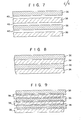
- Fig. 6 shows a further embodiment of the present invention wherein the first and second kinds of signals are recorded on two tracks adjacent to each other. More specifically, a magnetic disc 26 has a recording track 32 on which the first kind of signal is recorded, and another recording track 34 on which the second kind of signal is recorded, and these recording tracks 32 and 34 are arranged alternately on the magnetic disc 26 in the radial direction thereof. The first kind of signal is recorded on the track 32 with high linear recording density, and the second kind of signal is then recorded on the track 34 with low linear recording density.
- the recording medium is not limited to the magnetic disc but may be a magnetic sheet or a magnetic tape.
- Figs. 7 through 9 show various kinds of track arrangements. More specifically, Fig. 7 shows a track 36 on which the first kind of signal is recorded, and a track 38 on which the second kind of signal is recorded, alternately arranged with a non-recording area 40 interposed therebetween. Fig. 8 shows both sides of the track 36 in contact with those of the track 38. F ig. 9 shows both sides of the track 36 overlapping those of the track 38.
- the first kind of signal is recorded with a linear recording density higher than that of the second kind of signal recorded later, and the reproduced output level of the first kind of signal is not decreased significantly by the recording of the second kind of signal but both kinds of signals can be reproduced with high quality, even in those cases where a space occurs between tracks 36 and 38 (Fig. 7), where both sides of the track 36 are in contact with those of the track 38 (Fig. 8), and where both sides of the track 36 overlap with those of the track 38 (Fig. 9).
- the linear recording density of the later-recorded signal may be lower than that of the previously-recorded signal. Both of the signals can be reproduced with high quality in this manner. Therefore, the track density can be enhanced and the area recording density can be increased.
- One embodiment of the invention provides a perpendicular magnetic recording method for recording signals on a magnetic recording medium which has perpendicular magnetic anisotropy, comprising steps of:
- the method is characterized in that the second linear recording density is 15 or more kilobits per inch lower than the first linear recording density, and the first signal 22 has been recorded on an area which is under the influence of a magnetic field generated at the time of recording the second signal 24.
- the first signal may be recorded on a first recording track 36 and the second signal on a second recording track 38, the first recording track being partly overlapped with the second recording track.
- the first kind of signal may be recorded on a first recording track 36 and the second kind of signal on a second recording track 38, both sideedges of the first and the second recording tracks being in contact with each other.
- the first signal may be recorded on a first recording track 36 and the second signal on a second recording track 38, a non-recording area 40 being interposed between the first and the second recording tracks.
Landscapes
- Digital Magnetic Recording (AREA)
- Recording Or Reproducing By Magnetic Means (AREA)
Applications Claiming Priority (2)
| Application Number | Priority Date | Filing Date | Title |
|---|---|---|---|
| JP57174307A JPS5963005A (ja) | 1982-10-04 | 1982-10-04 | 磁気記録方式 |
| JP174307/82 | 1982-10-04 |
Publications (2)
| Publication Number | Publication Date |
|---|---|
| EP0105502A1 true EP0105502A1 (de) | 1984-04-18 |
| EP0105502B1 EP0105502B1 (de) | 1987-04-08 |
Family
ID=15976365
Family Applications (1)
| Application Number | Title | Priority Date | Filing Date |
|---|---|---|---|
| EP83109821A Expired EP0105502B1 (de) | 1982-10-04 | 1983-09-30 | Aufzeichnungsverfahren bei senkrechter Magnetisierung |
Country Status (4)
| Country | Link |
|---|---|
| US (1) | US4646168A (de) |
| EP (1) | EP0105502B1 (de) |
| JP (1) | JPS5963005A (de) |
| DE (1) | DE3370891D1 (de) |
Cited By (1)
| Publication number | Priority date | Publication date | Assignee | Title |
|---|---|---|---|---|
| EP0161875A2 (de) * | 1984-05-10 | 1985-11-21 | Kabushiki Kaisha Toshiba | Senkrechte Magnetaufzeichnungsmethode und Gerät |
Families Citing this family (17)
| Publication number | Priority date | Publication date | Assignee | Title |
|---|---|---|---|---|
| US6873482B1 (en) * | 1999-03-05 | 2005-03-29 | Yung-Chieh Hsieh | Magnetic recording drive with continuous magnetic servo system |
| US6999279B2 (en) * | 2002-10-29 | 2006-02-14 | Imation Corp. | Perpendicular patterned magnetic media |
| US20150049401A1 (en) * | 2010-12-09 | 2015-02-19 | Matthew P. Dugas | Perpendicular timing-based servo heads |
| US9324362B1 (en) | 2014-11-24 | 2016-04-26 | Seagate Technology Llc | Post-write scan operations for interlaced magnetic recording |
| US9773517B2 (en) | 2014-11-24 | 2017-09-26 | Seagate Technology Llc | Dual writer head design |
| US9524743B2 (en) | 2014-11-24 | 2016-12-20 | Seagate Technology Llc | Heat assisted magnetic recording for bit-patterned media |
| US9601154B2 (en) | 2014-11-24 | 2017-03-21 | Seagate Technology Llc | Prioritized random access for magnetic recording |
| US9728206B2 (en) | 2014-11-24 | 2017-08-08 | Seagate Technology Llc | Interlaced magnetic recording |
| US9747942B2 (en) | 2014-11-24 | 2017-08-29 | Seagate Technology Llc | Variable written track widths for attribute-based storage |
| US9842047B2 (en) * | 2014-11-24 | 2017-12-12 | Seagate Technology Llc | Non-sequential write for sequential read back |
| US9818445B2 (en) | 2016-01-12 | 2017-11-14 | Seagate Technology Llc | Magnetic storage device readers |
| US10210891B1 (en) | 2016-01-28 | 2019-02-19 | Seagate Technology Llc | Dual writer head design utilizing two writers of different sizes for writing interlaced data tracks |
| US9805741B1 (en) | 2016-01-29 | 2017-10-31 | Seagate Technology Llc | Write current parameter selection for magnetic recording |
| US9805744B1 (en) | 2016-04-01 | 2017-10-31 | Seagate Technology Llc | Dual writer design in interlaced magnetic recording |
| US9672851B1 (en) | 2016-05-04 | 2017-06-06 | Seagate Technology Llc | Single writer interlaced magnetic recording |
| US9830940B1 (en) | 2016-05-13 | 2017-11-28 | Seagate Technology Llc | Heat-assisted shingled magnetic recording with variable track widths |
| US10199066B1 (en) | 2018-03-01 | 2019-02-05 | Seagate Technology Llc | Write management of physically coupled storage areas |
Citations (5)
| Publication number | Priority date | Publication date | Assignee | Title |
|---|---|---|---|---|
| US3188615A (en) * | 1961-05-29 | 1965-06-08 | Ampex | Recording and reproducing system |
| US3732364A (en) * | 1971-04-21 | 1973-05-08 | Hitachi Ltd | Magnetic tape recording and reproducing system |
| US3945035A (en) * | 1972-09-25 | 1976-03-16 | Douglas Goldman | Method and means for filtering and amplifying signal components of desired frequency |
| DE2916473A1 (de) * | 1978-04-25 | 1979-10-31 | Cii Honeywell Bull | Regelverfahren fuer das auslesesignal eines informationstraegers und vorrichtung zur durchfuehrung des verfahrens |
| DE3229811A1 (de) * | 1981-08-17 | 1983-02-24 | N.V. Philips' Gloeilampenfabrieken, 5621 Eindhoven | Verfahren zum schreiben bzw. wiedergeben stereophonischer information in einem magnetischen aufzeichnungstraeger, vorrichtung zum durchfuehren des verfahrens, magnetischer aufzeichnungstraeger und verstaerkerschaltung zur anwendung in einer vorrichtung zum durchfuehren des verfahrens |
Family Cites Families (5)
| Publication number | Priority date | Publication date | Assignee | Title |
|---|---|---|---|---|
| DE1130899B (de) * | 1958-12-12 | 1962-06-07 | Siemens Ag | Verfahren und Anordnung zum Aufzeichnen und Abtasten von Magnetogrammen |
| US4318141A (en) * | 1979-12-07 | 1982-03-02 | International Business Machines Corp. | Buried servo recording systems and methods |
| US4313140A (en) * | 1979-12-07 | 1982-01-26 | International Business Machines Corporation | Buried control signal recording systems and method |
| JPS56134303A (en) * | 1980-03-25 | 1981-10-21 | Matsushita Electric Ind Co Ltd | Signal recording system |
| JPS5760506A (en) * | 1980-09-26 | 1982-04-12 | Hitachi Ltd | Magnetic recording and reproducing method |
-
1982
- 1982-10-04 JP JP57174307A patent/JPS5963005A/ja active Granted
-
1983
- 1983-09-30 DE DE8383109821T patent/DE3370891D1/de not_active Expired
- 1983-09-30 EP EP83109821A patent/EP0105502B1/de not_active Expired
-
1986
- 1986-03-28 US US06/845,488 patent/US4646168A/en not_active Expired - Lifetime
Patent Citations (5)
| Publication number | Priority date | Publication date | Assignee | Title |
|---|---|---|---|---|
| US3188615A (en) * | 1961-05-29 | 1965-06-08 | Ampex | Recording and reproducing system |
| US3732364A (en) * | 1971-04-21 | 1973-05-08 | Hitachi Ltd | Magnetic tape recording and reproducing system |
| US3945035A (en) * | 1972-09-25 | 1976-03-16 | Douglas Goldman | Method and means for filtering and amplifying signal components of desired frequency |
| DE2916473A1 (de) * | 1978-04-25 | 1979-10-31 | Cii Honeywell Bull | Regelverfahren fuer das auslesesignal eines informationstraegers und vorrichtung zur durchfuehrung des verfahrens |
| DE3229811A1 (de) * | 1981-08-17 | 1983-02-24 | N.V. Philips' Gloeilampenfabrieken, 5621 Eindhoven | Verfahren zum schreiben bzw. wiedergeben stereophonischer information in einem magnetischen aufzeichnungstraeger, vorrichtung zum durchfuehren des verfahrens, magnetischer aufzeichnungstraeger und verstaerkerschaltung zur anwendung in einer vorrichtung zum durchfuehren des verfahrens |
Cited By (3)
| Publication number | Priority date | Publication date | Assignee | Title |
|---|---|---|---|---|
| EP0161875A2 (de) * | 1984-05-10 | 1985-11-21 | Kabushiki Kaisha Toshiba | Senkrechte Magnetaufzeichnungsmethode und Gerät |
| EP0161875A3 (en) * | 1984-05-10 | 1987-10-28 | Kabushiki Kaisha Toshiba | Perpendicular magnetic recording method & apparatus |
| US4719520A (en) * | 1984-05-10 | 1988-01-12 | Kabushiki Kaisha Toshiba | Method and apparatus for setting recording current in perpendicular magnetic recording apparatus |
Also Published As
| Publication number | Publication date |
|---|---|
| JPS5963005A (ja) | 1984-04-10 |
| US4646168A (en) | 1987-02-24 |
| DE3370891D1 (en) | 1987-05-14 |
| EP0105502B1 (de) | 1987-04-08 |
| JPH0415521B2 (de) | 1992-03-18 |
Similar Documents
| Publication | Publication Date | Title |
|---|---|---|
| US4646168A (en) | Perpendicular magnetic recording method | |
| US7436611B2 (en) | Method of servo writing for magnetic recording system, magnetic recording system | |
| US5568331A (en) | Method of head positioning and magnetic recording disk drive using the same | |
| US5138511A (en) | Magnetic recording disk in which the level of the surface of the data tracks, and servo tracks is higher than that of the guardbands | |
| US4652945A (en) | Flux sensitive tracking | |
| KR20010041116A (ko) | 자기디스크장치 | |
| US4786991A (en) | Magnetic recording/reproduction apparatus | |
| US4939608A (en) | Low-noise magnetic read/write head | |
| EP0064099B1 (de) | Signaltrennung in magnetischen Aufzeichnungssystemen mit Servosignalen auf einer unterliegenden Spur | |
| US6091566A (en) | Magnetoresistive head and hard drive system having offsets from center of the servo area to minimize microjogging | |
| JPS62121917A (ja) | ベリ−ドサ−ボ方式用薄膜磁気ヘツド | |
| JPS60263313A (ja) | 磁気記録媒体 | |
| JPS62185212A (ja) | 磁気記録ヘツド | |
| JP2002015420A (ja) | ディスクリート・トラック型磁気ディスク媒体の欠陥検査方法 | |
| JPH073448Y2 (ja) | 磁気ヘツド | |
| JPH0740381B2 (ja) | 光記録媒体 | |
| JPH0125124B2 (de) | ||
| JPS5918770B2 (ja) | 磁気デイスク装置 | |
| JPS61202388A (ja) | ベリ−ドサ−ボ方式用磁気2重層デイスク | |
| JPS59129904A (ja) | 磁気記録再生方式 | |
| JPS6220121A (ja) | 信号再生装置 | |
| JPS59113519A (ja) | 磁気円盤用の磁気ヘツド | |
| JPS6028013A (ja) | 磁気ヘツド | |
| JPH0217844B2 (de) | ||
| JPS62185214A (ja) | 磁気ヘツド装置 |
Legal Events
| Date | Code | Title | Description |
|---|---|---|---|
| PUAI | Public reference made under article 153(3) epc to a published international application that has entered the european phase |
Free format text: ORIGINAL CODE: 0009012 |
|
| 17P | Request for examination filed |
Effective date: 19830930 |
|
| AK | Designated contracting states |
Designated state(s): DE FR GB IT NL |
|
| RAP1 | Party data changed (applicant data changed or rights of an application transferred) |
Owner name: KABUSHIKI KAISHA TOSHIBA |
|
| GRAA | (expected) grant |
Free format text: ORIGINAL CODE: 0009210 |
|
| AK | Designated contracting states |
Kind code of ref document: B1 Designated state(s): DE FR GB NL |
|
| REF | Corresponds to: |
Ref document number: 3370891 Country of ref document: DE Date of ref document: 19870514 |
|
| ET | Fr: translation filed | ||
| PLBE | No opposition filed within time limit |
Free format text: ORIGINAL CODE: 0009261 |
|
| STAA | Information on the status of an ep patent application or granted ep patent |
Free format text: STATUS: NO OPPOSITION FILED WITHIN TIME LIMIT |
|
| 26N | No opposition filed | ||
| PGFP | Annual fee paid to national office [announced via postgrant information from national office to epo] |
Ref country code: FR Payment date: 19970909 Year of fee payment: 15 |
|
| PGFP | Annual fee paid to national office [announced via postgrant information from national office to epo] |
Ref country code: GB Payment date: 19970922 Year of fee payment: 15 |
|
| PGFP | Annual fee paid to national office [announced via postgrant information from national office to epo] |
Ref country code: NL Payment date: 19970929 Year of fee payment: 15 |
|
| PGFP | Annual fee paid to national office [announced via postgrant information from national office to epo] |
Ref country code: DE Payment date: 19971010 Year of fee payment: 15 |
|
| PG25 | Lapsed in a contracting state [announced via postgrant information from national office to epo] |
Ref country code: GB Free format text: LAPSE BECAUSE OF NON-PAYMENT OF DUE FEES Effective date: 19980930 |
|
| PG25 | Lapsed in a contracting state [announced via postgrant information from national office to epo] |
Ref country code: NL Free format text: LAPSE BECAUSE OF NON-PAYMENT OF DUE FEES Effective date: 19990401 |
|
| GBPC | Gb: european patent ceased through non-payment of renewal fee |
Effective date: 19980930 |
|
| PG25 | Lapsed in a contracting state [announced via postgrant information from national office to epo] |
Ref country code: FR Free format text: LAPSE BECAUSE OF NON-PAYMENT OF DUE FEES Effective date: 19990531 |
|
| NLV4 | Nl: lapsed or anulled due to non-payment of the annual fee |
Effective date: 19990401 |
|
| PG25 | Lapsed in a contracting state [announced via postgrant information from national office to epo] |
Ref country code: DE Free format text: LAPSE BECAUSE OF NON-PAYMENT OF DUE FEES Effective date: 19990701 |
|
| REG | Reference to a national code |
Ref country code: FR Ref legal event code: ST |