EP0104845A2 - Vorrichtung zum Steuern von Prozessen - Google Patents
Vorrichtung zum Steuern von Prozessen Download PDFInfo
- Publication number
- EP0104845A2 EP0104845A2 EP83305430A EP83305430A EP0104845A2 EP 0104845 A2 EP0104845 A2 EP 0104845A2 EP 83305430 A EP83305430 A EP 83305430A EP 83305430 A EP83305430 A EP 83305430A EP 0104845 A2 EP0104845 A2 EP 0104845A2
- Authority
- EP
- European Patent Office
- Prior art keywords
- transfer function
- output
- input
- accordance
- signal
- Prior art date
- Legal status (The legal status is an assumption and is not a legal conclusion. Google has not performed a legal analysis and makes no representation as to the accuracy of the status listed.)
- Granted
Links
Images
Classifications
-
- G—PHYSICS
- G05—CONTROLLING; REGULATING
- G05B—CONTROL OR REGULATING SYSTEMS IN GENERAL; FUNCTIONAL ELEMENTS OF SUCH SYSTEMS; MONITORING OR TESTING ARRANGEMENTS FOR SUCH SYSTEMS OR ELEMENTS
- G05B13/00—Adaptive control systems, i.e. systems automatically adjusting themselves to have a performance which is optimum according to some preassigned criterion
- G05B13/02—Adaptive control systems, i.e. systems automatically adjusting themselves to have a performance which is optimum according to some preassigned criterion electric
- G05B13/04—Adaptive control systems, i.e. systems automatically adjusting themselves to have a performance which is optimum according to some preassigned criterion electric involving the use of models or simulators
- G05B13/042—Adaptive control systems, i.e. systems automatically adjusting themselves to have a performance which is optimum according to some preassigned criterion electric involving the use of models or simulators in which a parameter or coefficient is automatically adjusted to optimise the performance
- G05B13/045—Adaptive control systems, i.e. systems automatically adjusting themselves to have a performance which is optimum according to some preassigned criterion electric involving the use of models or simulators in which a parameter or coefficient is automatically adjusted to optimise the performance using a perturbation signal
Definitions
- the present invention relates to a process control apparatus for digitally controlling a process.
- a transfer function of a process is identified in accordance with an input signal (control variable) to the process and an output signal (controlled variable) therefrom.
- PID parameters are then determined in accordance with an identified transfer function, thereby controlling the process by using PID parameters.
- the process is assumed to be a single input/output process when the transfer function is identified.
- the conventional process control apparatus serves only as a single loop controller having a single control loop.
- many processes function as multi-input/output processes.
- a process control apparatus for an N- (where N is any natural number) input/output process, comprising a PID controller for controlling said process in accordance with PID parameters and control errors respectively as differences between N outputs from said process and set-point values for the N outputs, a signal generator for superposing N persistently exciting identification signals respectively on the N inputs to said process, a pulse transfer function identifying circuit for identifying Z-transfer functions corresponding to all input-to-output combinations in accordance with the N inputs to said process and the N outputs from said process while the N persistently exciting identification signals are respectively superposed on the N inputs, an S-transfer function calculator for calculating an S-transfer function of said process in accordance with identified Z-transfer functions, and a circuit for matching an S-transfer function between a set-point value of a process control system and a process output which is obtained from a calculated S-transfer function with an S-transfer function between a set-point value and the process
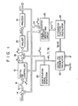
- Fig. 1 is a block diagram showing the overall configuration of the process control system.
- the process control system comprises a closed loop control system having a multi-input/output process 10 and a digital PID controller 12.
- the process 10 has a plurality of controlled variables (process outputs) such as temperature, humidity, pressure, flow rate, etc., and a plurality of control variables (process inputs).
- Each controlled variable is influenced by the corresponding control variable. However, each controlled variable may be influenced by other control variables in some cases.
- the closed loop control system has N control loops. All signals of the control system comprise N-dimensional vectors, respectively.
- a set-point signal r i (t) and the process output signal y i (t) are respectively supplied to a (+) input terminal and a (-) input terminal of an adder 14.
- the control error signal e i (t) is sampled to produce a discrete-time control error signal e i *(k) by a sampler 16.
- the signal e i *(k) is supplied to the digital PID controller 12.
- a sampling period ⁇ i may vary between loops.
- k t/ T ..
- the controller 12 produces a control variable u 0i *(k) for controlling each variable to be controlled.
- the control system receives a persistently exciting identification signal. More particularly, the output u oi *(k) from the controller 12 and an output v i *(k) from an identification signal generator 20 are added by an adder 18 to produce a control signal u. * (k). A control signal u i (t) along a continuous time base is obtained from the control signal u i *(k) through a Oth-order holder 22. The control variable u i (t) is then supplied to the process 10.
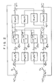
- Fig. 2 shows a closed loop control system of a 2-input/output process.
- This process has an interference between the inputs and the outputs, and has four transfer functions: transfer functions Gp ll (s) and Gp 22 (s) of the two main loops and interference transfer functions Gp 21 (s) and Gp 12 (s).
- Gp ij (s) indicates a transfer function between a process input signal u j (t) and a process output signal y i (t). Since the process is controlled by four transfer functions, the controller is also controlled by four transfer functions.
- sampling periods of the sampler are given as T1 and T 2 for the respective loops. Therefore, holders having the periods ⁇ 1 and ⁇ 2 are used, and identification signals v 1 *(k) and v 2 * (k) are used for the respective loops.
- the process output signal y i (t) from the process 10 is supplied to a sampler 24 which is operated in synchronism with the sampler 16.
- the sampler 24 samples the process output signal y i (t) and produces a signal y i * (k).
- the signal u i *(k) and the signal y i * (k) are supplied to a pulse transfer function identifying circuit 26.
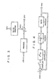
- the identified Z-transfer function i G ij (z i -1 ) is supplied to an S-transfer function calcu- lator 28 . .
- the Z-transfer function G ij (z i -1 ) is converted to an S-transfer function Gp ij (s).
- the S-transfer function Gp ij (s) is supplied to a digital PID parameter calculator 30.
- the parameter calculator 30 receives a mode signal PID/PI for determining the operating mode of the controller 12 and a response shape parameter ⁇ of the reference model.
- the parameter calculator 30 matches the S-transfer function of the closed loop control system 10 with the S-transfer function of the reference model to obtain the digital PID parameters Kc ij , Ti ij and Td... These parameters are supplied to the controller 12.
- the identification signal v i * (k) is superposed on the signal u oi *(k) of each loop.
- a maximum period sequence (M-sequence) signal is selected as an identification signal.
- the dynamic characteristics of the process during the closed loop control can be identified.
- the Z-transfer function of the process is identified in accordance with the discrete-time process inputs and outputs.
- equation (3) is substituted into equation (2), and equation (2) is represented by its components, the following is obtained:
- Equation (4) for the ith process output y i (k) may be rewritten in the following manner:
- Equation (5) indicates a model for an N-input/one- output process. Therefore, the N-input/N-output process can be represented by a combination of the N-input/one- output processes. Reducing fractions to a common denomination in equation (5), the following equation is obtained: for
- a parameter prediction technique used for identification of the one-input/output system can also be used for identification of the dynamic characteristics of the multi-input/output system.
- the Z-transfer function G(z -1 ) of the process is identified by a recursive least square (RLS) algorithm.
- the Z-transfer function can be identified by identifying unknown parameters a 1 *,..., a na*' b 11 *,..., b lnbl *,.., b Nl *,..., b NnbN *, and C 1 *,..., C nc * .
- the process model can be expressed in accordance with the RLS algorithm.
- T denotes the transpose.
- the RLS algorithm can be given as follows: where X(k) is the forgetting factor.
- the Z-transfer functions G il (z i -1 ),..., G iN (z i -1 ) for one process output y i *(k) are obtained.
- the identifying circuit 26 repeats the algorithm N times to identify the Z-transfer functions for all process outputs.
- a recursive extended least square (RELS) algorithm, a recursive maximum likelihood or the like may be used as an unknown parameter prediction technique instead of the RLS algorithm.
- the vectors ⁇ (k) and 6 of the RELS algorithm are given as follows:
- the dynamic characteristics of process can be identified as the Z-transfer function.
- the PID control parameters are obtained from the S-transfer function in a manner to be described later.
- a Z-transfer function G(z -1 ) of the subprocess is defined as follows:
- the step response x n is approximated by an m-order polynomial as a function of t, so that for n ⁇ ⁇ t ⁇ (n+1) ⁇
- the S-transfer function calculator 28 transforms each Z-transfer function G ij (z -1 ) to the S-transfer function Gp ij (s) by the above means.
- denominator polynomials of the transfer functions Gp ij (s) differ from each other.
- the denominator polynomials are then reduced to a common denominator to obtain the general transfer function for the multi-input/output processes.
- the transfer function Gp(s) for the multi-input/output process 10 is obtained as follows: for a i ⁇ R 1 , a 0 ⁇ 0, B i ⁇ R NXN , and B 0 ⁇ 0
- the operation of the digital PID parameter calculator 30 will be described wherein the PI D parameters Kc, Ti and Td for the digital PID controller 12 are tuned in accordance with the identified transfer function Gp(s).
- ⁇ i in equation (39) is a difference operator and corresponds to the well-known differential operator s for a continuous time system.
- T . is decreased to zero
- k/ ⁇ i becomes k/s
- k ⁇ i becomes ks.
- the approximate expression of the PID controller 12 is obtained along a continuous time base as follows. For example, the controller performs the P operation and the sampler and holder are operated with a period of T. .
- the controller can be approximated by the expression k(l - z i -1 )/ ⁇ i s.
- the sampling frequencies differ in accordance with the loops, so that the following matrices are given:
- the response shape of the reference model can be easily changed in accordance with the response shape parameter ⁇ i .
- the response shape parameter ⁇ i can be set independently for each loop, so that the reference model can be set independently for each loop.
- This parameter ⁇ i is selected in the range between 0 and 1.0.
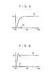
- Figs. 5 and 6 show step responses of the designed closed loop control system when the response shape parameters ⁇ i are given as
- Fig. 5 shows process outputs y, and y 2 when the set-point signal r 1 changes in a stepwise manner. The output y 1 has substantially no overshoot.
- Fig. 6 shows process outputs y 1 and y 2 when the set-point signal r 2 changes in a stepwise manner. The output y 2 has about 10% overshoot.
- Equations (55), (50) and (45) are substituted into equation (43) to obtain the following equation: -
- a process control apparatus wherein the dynamic characteristics of the multi-input/output process are identified during the closed loop control, and model matching is performed using the identified dynamic characteristics, thereby automatically tuning the digital PID parameters of the controller. Therefore, the period required for tuning the controller can be shortened, so that the process can be effectively operated. Furthermore, the decoupled reference model is selected in model matching, so that the multi-input/output process having an interference between the inputs and the outputs can be properly controlled since the loops are independently controlled. In addition to these advantages, the response shape of the reference model can be changed in accordance with a change in parameter for each loop. Therefore, a process control apparatus can be applied to all types of process. In the above embodiment, one-input/output processes and a multi-input/output process having no interference are included, so that the apparatus according to the present invention can be readily applied to any type of process.
Landscapes
- Engineering & Computer Science (AREA)
- Health & Medical Sciences (AREA)
- Artificial Intelligence (AREA)
- Computer Vision & Pattern Recognition (AREA)
- Evolutionary Computation (AREA)
- Medical Informatics (AREA)
- Software Systems (AREA)
- Physics & Mathematics (AREA)
- General Physics & Mathematics (AREA)
- Automation & Control Theory (AREA)
- Feedback Control In General (AREA)
Applications Claiming Priority (2)
| Application Number | Priority Date | Filing Date | Title |
|---|---|---|---|
| JP166040/82 | 1982-09-25 | ||
| JP57166040A JP2563894B2 (ja) | 1982-09-25 | 1982-09-25 | 多入出力サンプル値pid制御装置 |
Publications (3)
| Publication Number | Publication Date |
|---|---|
| EP0104845A2 true EP0104845A2 (de) | 1984-04-04 |
| EP0104845A3 EP0104845A3 (en) | 1985-01-23 |
| EP0104845B1 EP0104845B1 (de) | 1989-12-13 |
Family
ID=15823832
Family Applications (1)
| Application Number | Title | Priority Date | Filing Date |
|---|---|---|---|
| EP83305430A Expired EP0104845B1 (de) | 1982-09-25 | 1983-09-15 | Vorrichtung zum Steuern von Prozessen |
Country Status (6)
| Country | Link |
|---|---|
| US (1) | US4563734A (de) |
| EP (1) | EP0104845B1 (de) |
| JP (1) | JP2563894B2 (de) |
| AU (1) | AU543196B2 (de) |
| CA (1) | CA1213020A (de) |
| DE (1) | DE3380971D1 (de) |
Cited By (11)
| Publication number | Priority date | Publication date | Assignee | Title |
|---|---|---|---|---|
| EP0228813A3 (en) * | 1985-11-27 | 1988-12-14 | Nippondenso Co., Ltd. | Air conditioner for automobiles |
| EP0558179A3 (en) * | 1992-02-28 | 1994-07-06 | Hewlett Packard Co | Determination of open loop responses from closed loop measurements |
| US5479356A (en) * | 1990-10-18 | 1995-12-26 | Hewlett-Packard Company | Computer-aided method of designing a carry-lookahead adder |
| SG96542A1 (en) * | 1997-08-30 | 2003-06-16 | Univ Singapore | Apparatus for relay based multiple point process frequency response estimation and control tuning |
| RU2243584C2 (ru) * | 2003-03-24 | 2004-12-27 | Шубладзе Александр Михайлович | Способ оптимальной автоматической настройки системы управления |
| RU2304298C2 (ru) * | 2005-10-05 | 2007-08-10 | Закрытое акционерное общество "ЭлеСи" | Способ самонастройки системы управления объектом и устройство для его реализации |
| RU2327196C1 (ru) * | 2006-12-05 | 2008-06-20 | Открытое Акционерное Общество "Научно-Исследовательский И Проектный Институт Карбамида И Продуктов Органического Синтеза" (Оао Ниик) | Каскадная двухканальная самонастраивающаяся система комбинированного управления |
| RU2435187C2 (ru) * | 2010-02-02 | 2011-11-27 | Виктор Иванович Соловьев | Интеллектуальная система управления сложными организованными объектами |
| RU2522032C1 (ru) * | 2010-05-25 | 2014-07-10 | АйЭйчАй КОРПОРЕЙШН | Способ и устройство автоматической регулировки составляющей прямой связи для подавления избыточного отклика на ступенчатое воздействие во время ступенчатого слежения |
| RU2522033C1 (ru) * | 2010-05-25 | 2014-07-10 | АйЭйчАй КОРПОРЕЙШН | Способ и устройство автоматической регулировки составляющей прямой связи для подавления избыточного отклика на ступенчатое воздействие во время ступенчатого слежения |
| US10700605B1 (en) | 2018-12-12 | 2020-06-30 | Infineon Technologies Austria Ag | Electrical power converter with predictor |
Families Citing this family (40)
| Publication number | Priority date | Publication date | Assignee | Title |
|---|---|---|---|---|
| US4646226A (en) * | 1983-01-28 | 1987-02-24 | Measurex Corporation | System and process for identifying and updating tuning constants |
| JPS59167706A (ja) * | 1983-03-14 | 1984-09-21 | Toshiba Corp | 多入出力サンプル値i−pd制御装置 |
| JPH07104715B2 (ja) * | 1984-01-18 | 1995-11-13 | 株式会社日立製作所 | パラメ−タの同定方法 |
| DE3408551A1 (de) * | 1984-03-08 | 1985-09-12 | Siemens AG, 1000 Berlin und 8000 München | Verfahren zum verringern von bahnfehlern bei rechnergesteuerten werkzeugmaschinen oder industrierobotern |
| DE3572740D1 (en) * | 1984-04-13 | 1989-10-05 | Toshiba Kk | Process control apparatus |
| DE3576314D1 (de) * | 1984-10-19 | 1990-04-12 | Nippon Denso Co | Kraftfahrzeugklimaanlage. |
| DE3518383C1 (de) * | 1985-05-22 | 1986-12-04 | Boge Gmbh, 5208 Eitorf | Beschleunigungsmesser |
| DE3518382C1 (de) * | 1985-05-22 | 1986-12-04 | Boge Gmbh, 5208 Eitorf | Vorrichtung zur Messung der Beschleunigung von Fahrzeugteilen |
| JPS6314202A (ja) * | 1986-07-04 | 1988-01-21 | Hitachi Ltd | プラント制御方法 |
| US4893480A (en) * | 1987-03-13 | 1990-01-16 | Nippondenso Co., Ltd. | Refrigeration cycle control apparatus |
| JPH0298701A (ja) * | 1988-10-05 | 1990-04-11 | Toshiba Corp | 制御装置 |
| JP2882586B2 (ja) * | 1989-01-13 | 1999-04-12 | 株式会社東芝 | 適応制御装置 |
| JP2835061B2 (ja) * | 1989-02-23 | 1998-12-14 | 株式会社東芝 | 適応制御装置 |
| WO1991005293A1 (en) * | 1989-10-02 | 1991-04-18 | Rosemount Inc. | Field-mounted control unit |
| US5126933A (en) * | 1990-02-07 | 1992-06-30 | White Iii Charles A | Self-learning memory unit for process controller and self-updating function generator |
| JPH0580810A (ja) * | 1991-09-20 | 1993-04-02 | Hitachi Ltd | サーボ制御方法及び装置 |
| US5278775A (en) * | 1991-09-30 | 1994-01-11 | The University Of Akron | Method of tightening threaded fasteners |
| US5691896A (en) * | 1995-08-15 | 1997-11-25 | Rosemount, Inc. | Field based process control system with auto-tuning |
| CA2229937A1 (en) * | 1995-09-22 | 1997-03-27 | Rosemount Inc. | Adaptive bias controller |
| US5818714A (en) * | 1996-08-01 | 1998-10-06 | Rosemount, Inc. | Process control system with asymptotic auto-tuning |
| US6185468B1 (en) * | 1998-02-20 | 2001-02-06 | Impact Systems, Inc. | Decoupling controller for use with a process having two input variables and two output variables |
| US6442445B1 (en) | 1999-03-19 | 2002-08-27 | International Business Machines Corporation, | User configurable multivariate time series reduction tool control method |
| WO2001098844A2 (en) * | 2000-06-20 | 2001-12-27 | Liu D | Methods of designing optimal pid controllers |
| US20050065621A1 (en) * | 2000-06-20 | 2005-03-24 | Danyang Liu | Methods of designing optimal linear controllers |
| WO2002044573A1 (de) * | 2000-12-02 | 2002-06-06 | Ina-Schaeffler Kg | Verschiebegelenk |
| DE102004040774B3 (de) * | 2004-08-23 | 2006-04-27 | Siemens Ag | Verfahren und Anordnung zur Online-Regelung eines Batch-Prozesses in einem Bioreaktor |
| JP4520819B2 (ja) * | 2004-10-25 | 2010-08-11 | 大陽日酸株式会社 | プラントの故障予測方法 |
| US20090195224A1 (en) * | 2008-01-31 | 2009-08-06 | Basler Electric Company | Digital Excitation Control System Utilizing Self-Tuning PID Gains and an Associated Method of Use |
| US8866626B2 (en) | 2008-01-31 | 2014-10-21 | Basler Electric Company | System and method for detecting generator incipient failures |
| US8275488B2 (en) * | 2008-01-31 | 2012-09-25 | Basler Electric Co. | Digital excitation control system utilizing swarm intelligence and an associated method of use |
| US20100039884A1 (en) * | 2008-08-13 | 2010-02-18 | Southern Pump & Tank Company, Llc | Fuel mixing system |
| WO2011032252A1 (en) * | 2009-09-15 | 2011-03-24 | Consortium De Recherche Brp - Université De Sherbrooke S.E.N.C. | Method of controlling a hydraulic continuously variable transmission |
| US8798882B2 (en) | 2009-09-15 | 2014-08-05 | Consortium de Recherche BRP—Universite de Sherbrooke S.E.N.C. | Method of controlling a hydraulic continuously variable transmission |
| RU2444040C2 (ru) * | 2010-05-31 | 2012-02-27 | Государственное образовательное учреждение высшего профессионального образования "Тамбовский государственный технический университет" (ГОУ ВПО ТГТУ) | Способ и система оптимального управления объектами двойного интегрирования |
| US9574511B2 (en) | 2014-07-24 | 2017-02-21 | Basler Electric Company | System and method for a load anticipation feature and its tuning method for a generating set |
| US10126053B2 (en) | 2016-09-02 | 2018-11-13 | International Business Machines Corporation | Precision dual annealing apparatus |
| US10570015B2 (en) | 2016-09-02 | 2020-02-25 | International Business Machines Corporation | Minimizing tin loss during thermal processing of kesterite films |
| WO2018112174A1 (en) * | 2016-12-15 | 2018-06-21 | Hansen Peter D | Multivariable process control-diagonal matrix controller cascaded with a decoupling matrix |
| CN109270839B (zh) * | 2018-09-26 | 2021-09-14 | 沈阳工业大学 | 一种无自平衡能力对象的串联控制方法 |
| CN112421083A (zh) * | 2020-11-19 | 2021-02-26 | 苏州智检通联技术有限公司 | 质子交换膜燃料电池阳极氢气解耦控制方法、系统及装置 |
Family Cites Families (8)
| Publication number | Priority date | Publication date | Assignee | Title |
|---|---|---|---|---|
| US3718813A (en) * | 1972-01-19 | 1973-02-27 | O Williams | Technique for correlation method of determining system impulse response |
| US4067060A (en) * | 1976-07-06 | 1978-01-03 | Canadian Patents And Development Limited | Transfer function measurement |
| GB1603825A (en) * | 1977-05-17 | 1981-12-02 | Jones K R | Three term (pid) controllers |
| US4232364A (en) * | 1978-12-18 | 1980-11-04 | Honeywell Inc. | Adaptive sampled-data controller |
| JPS5723108A (en) * | 1980-07-18 | 1982-02-06 | Toshiba Corp | Sampled-value pid controller |
| AU528431B2 (en) * | 1980-07-18 | 1983-04-28 | Tokyo Shibaura Denki Kabushiki Kaisha | Process control |
| US4407013A (en) * | 1980-10-20 | 1983-09-27 | Leeds & Northrup Company | Self tuning of P-I-D controller by conversion of discrete time model identification parameters |
| US4539633A (en) * | 1982-06-16 | 1985-09-03 | Tokyo Shibaura Denki Kabushiki Kaisha | Digital PID process control apparatus |
-
1982
- 1982-09-25 JP JP57166040A patent/JP2563894B2/ja not_active Expired - Lifetime
-
1983
- 1983-09-13 US US06/531,649 patent/US4563734A/en not_active Expired - Lifetime
- 1983-09-13 AU AU19087/83A patent/AU543196B2/en not_active Ceased
- 1983-09-15 DE DE8383305430T patent/DE3380971D1/de not_active Expired - Lifetime
- 1983-09-15 EP EP83305430A patent/EP0104845B1/de not_active Expired
- 1983-09-23 CA CA000437446A patent/CA1213020A/en not_active Expired
Cited By (12)
| Publication number | Priority date | Publication date | Assignee | Title |
|---|---|---|---|---|
| EP0228813A3 (en) * | 1985-11-27 | 1988-12-14 | Nippondenso Co., Ltd. | Air conditioner for automobiles |
| US5479356A (en) * | 1990-10-18 | 1995-12-26 | Hewlett-Packard Company | Computer-aided method of designing a carry-lookahead adder |
| EP0558179A3 (en) * | 1992-02-28 | 1994-07-06 | Hewlett Packard Co | Determination of open loop responses from closed loop measurements |
| SG96542A1 (en) * | 1997-08-30 | 2003-06-16 | Univ Singapore | Apparatus for relay based multiple point process frequency response estimation and control tuning |
| RU2243584C2 (ru) * | 2003-03-24 | 2004-12-27 | Шубладзе Александр Михайлович | Способ оптимальной автоматической настройки системы управления |
| RU2304298C2 (ru) * | 2005-10-05 | 2007-08-10 | Закрытое акционерное общество "ЭлеСи" | Способ самонастройки системы управления объектом и устройство для его реализации |
| RU2327196C1 (ru) * | 2006-12-05 | 2008-06-20 | Открытое Акционерное Общество "Научно-Исследовательский И Проектный Институт Карбамида И Продуктов Органического Синтеза" (Оао Ниик) | Каскадная двухканальная самонастраивающаяся система комбинированного управления |
| RU2435187C2 (ru) * | 2010-02-02 | 2011-11-27 | Виктор Иванович Соловьев | Интеллектуальная система управления сложными организованными объектами |
| RU2522032C1 (ru) * | 2010-05-25 | 2014-07-10 | АйЭйчАй КОРПОРЕЙШН | Способ и устройство автоматической регулировки составляющей прямой связи для подавления избыточного отклика на ступенчатое воздействие во время ступенчатого слежения |
| RU2522033C1 (ru) * | 2010-05-25 | 2014-07-10 | АйЭйчАй КОРПОРЕЙШН | Способ и устройство автоматической регулировки составляющей прямой связи для подавления избыточного отклика на ступенчатое воздействие во время ступенчатого слежения |
| US10700605B1 (en) | 2018-12-12 | 2020-06-30 | Infineon Technologies Austria Ag | Electrical power converter with predictor |
| US11575322B2 (en) | 2018-12-12 | 2023-02-07 | Infineon Technologies Austria Ag | Electrical power converter |
Also Published As
| Publication number | Publication date |
|---|---|
| EP0104845B1 (de) | 1989-12-13 |
| JPS5955503A (ja) | 1984-03-30 |
| AU1908783A (en) | 1984-03-29 |
| JP2563894B2 (ja) | 1996-12-18 |
| DE3380971D1 (de) | 1990-01-18 |
| AU543196B2 (en) | 1985-04-04 |
| EP0104845A3 (en) | 1985-01-23 |
| US4563734A (en) | 1986-01-07 |
| CA1213020A (en) | 1986-10-21 |
Similar Documents
| Publication | Publication Date | Title |
|---|---|---|
| EP0104845A2 (de) | Vorrichtung zum Steuern von Prozessen | |
| EP0119765B1 (de) | 1-PD Regelvorrichtung mit getasteten Daten | |
| EP0139243B1 (de) | Prozesssteuerapparat | |
| EP0045857B1 (de) | Prozess-Steuerungsapparat | |
| Athans | The role and use of the stochastic linear-quadratic-Gaussian problem in control system design | |
| EP0379215B1 (de) | Entwurfsverfahren eines Steuerungssystems und Entwurfsunterstützungsgerät | |
| EP0099362B1 (de) | Verfahren und vorrichtung zum abstimmen eines pid-reglers | |
| EP0066785A1 (de) | Prozessregelungsapparat | |
| US5404289A (en) | Controller apparatus having improved transient response speed by means of self-tuning variable set point weighting | |
| EP0378093B1 (de) | Verfahren und Vorrichtung zur Gewinnung von Parametern in der Prozesssteuerung | |
| EP0037579A2 (de) | Verfahren zur selbstanpassenden, prädiktiven Regelung und selbstanpassendes prädiktives Regelungssystem | |
| JP2009510606A (ja) | プラント制御システム用オンディマンドの自動チューナ | |
| JPH0610761B2 (ja) | 調節計 | |
| EP0483364A1 (de) | Diskretes wiederholungssteuerverfahren und vorrichtung dafür | |
| JP2643506B2 (ja) | 工業用プロセスの予測制御装置 | |
| US20020022948A1 (en) | Method of adjusting characteristics of electronic part | |
| Haseyama et al. | An adaptive ARMA four-line lattice filter for spectral estimation with frequency weighting | |
| Toivonen | Multivariable adaptive control | |
| JPH04256102A (ja) | モデル予測制御装置 | |
| JPS6148163B2 (de) | ||
| EP0290190A2 (de) | Anordnung zum Vergleichen von Mustern | |
| JP3278459B2 (ja) | 適応型制御方法及び装置 | |
| Unbehauen | System identification methods using parameter estimation/a survey | |
| Haseyama et al. | A Method for realization of an ARMAX Lattice Filter | |
| Kamoun et al. | Implicit self-tuning control for a class of large-scale systems |
Legal Events
| Date | Code | Title | Description |
|---|---|---|---|
| PUAI | Public reference made under article 153(3) epc to a published international application that has entered the european phase |
Free format text: ORIGINAL CODE: 0009012 |
|
| 17P | Request for examination filed |
Effective date: 19830927 |
|
| AK | Designated contracting states |
Designated state(s): DE FR GB NL |
|
| RAP1 | Party data changed (applicant data changed or rights of an application transferred) |
Owner name: KABUSHIKI KAISHA TOSHIBA |
|
| PUAL | Search report despatched |
Free format text: ORIGINAL CODE: 0009013 |
|
| AK | Designated contracting states |
Designated state(s): DE FR GB NL |
|
| 17Q | First examination report despatched |
Effective date: 19870128 |
|
| GRAA | (expected) grant |
Free format text: ORIGINAL CODE: 0009210 |
|
| AK | Designated contracting states |
Kind code of ref document: B1 Designated state(s): DE FR GB NL |
|
| REF | Corresponds to: |
Ref document number: 3380971 Country of ref document: DE Date of ref document: 19900118 |
|
| ET | Fr: translation filed | ||
| PLBE | No opposition filed within time limit |
Free format text: ORIGINAL CODE: 0009261 |
|
| STAA | Information on the status of an ep patent application or granted ep patent |
Free format text: STATUS: NO OPPOSITION FILED WITHIN TIME LIMIT |
|
| 26N | No opposition filed | ||
| PGFP | Annual fee paid to national office [announced via postgrant information from national office to epo] |
Ref country code: FR Payment date: 19980909 Year of fee payment: 16 |
|
| PGFP | Annual fee paid to national office [announced via postgrant information from national office to epo] |
Ref country code: DE Payment date: 19980921 Year of fee payment: 16 |
|
| PGFP | Annual fee paid to national office [announced via postgrant information from national office to epo] |
Ref country code: NL Payment date: 19980929 Year of fee payment: 16 |
|
| REG | Reference to a national code |
Ref country code: GB Ref legal event code: 746 Effective date: 19981126 |
|
| REG | Reference to a national code |
Ref country code: FR Ref legal event code: D6 |
|
| PG25 | Lapsed in a contracting state [announced via postgrant information from national office to epo] |
Ref country code: NL Free format text: LAPSE BECAUSE OF NON-PAYMENT OF DUE FEES Effective date: 20000401 |
|
| PG25 | Lapsed in a contracting state [announced via postgrant information from national office to epo] |
Ref country code: FR Free format text: LAPSE BECAUSE OF NON-PAYMENT OF DUE FEES Effective date: 20000531 |
|
| NLV4 | Nl: lapsed or anulled due to non-payment of the annual fee |
Effective date: 20000401 |
|
| PG25 | Lapsed in a contracting state [announced via postgrant information from national office to epo] |
Ref country code: DE Free format text: LAPSE BECAUSE OF NON-PAYMENT OF DUE FEES Effective date: 20000701 |
|
| REG | Reference to a national code |
Ref country code: FR Ref legal event code: ST |
|
| PGFP | Annual fee paid to national office [announced via postgrant information from national office to epo] |
Ref country code: GB Payment date: 20000913 Year of fee payment: 18 |
|
| PG25 | Lapsed in a contracting state [announced via postgrant information from national office to epo] |
Ref country code: GB Free format text: LAPSE BECAUSE OF NON-PAYMENT OF DUE FEES Effective date: 20010915 |
|
| REG | Reference to a national code |
Ref country code: GB Ref legal event code: IF02 |
|
| GBPC | Gb: european patent ceased through non-payment of renewal fee |
Effective date: 20010915 |