EP0104591A2 - Befestigungsanordnung für Zubehöre für eine Patientenliege - Google Patents
Befestigungsanordnung für Zubehöre für eine Patientenliege Download PDFInfo
- Publication number
- EP0104591A2 EP0104591A2 EP83109335A EP83109335A EP0104591A2 EP 0104591 A2 EP0104591 A2 EP 0104591A2 EP 83109335 A EP83109335 A EP 83109335A EP 83109335 A EP83109335 A EP 83109335A EP 0104591 A2 EP0104591 A2 EP 0104591A2
- Authority
- EP
- European Patent Office
- Prior art keywords
- plate
- accessories
- bracket
- fastening arrangement
- area
- Prior art date
- Legal status (The legal status is an assumption and is not a legal conclusion. Google has not performed a legal analysis and makes no representation as to the accuracy of the status listed.)
- Granted
Links
- 239000012780 transparent material Substances 0.000 claims 1
- 239000000463 material Substances 0.000 description 2
- 241001046947 Ectropis obliqua Species 0.000 description 1
- FAPWRFPIFSIZLT-UHFFFAOYSA-M Sodium chloride Chemical compound [Na+].[Cl-] FAPWRFPIFSIZLT-UHFFFAOYSA-M 0.000 description 1
- 210000001015 abdomen Anatomy 0.000 description 1
- 238000010276 construction Methods 0.000 description 1
- 239000011780 sodium chloride Substances 0.000 description 1
Images

Classifications
-
- A—HUMAN NECESSITIES
- A61—MEDICAL OR VETERINARY SCIENCE; HYGIENE
- A61G—TRANSPORT, PERSONAL CONVEYANCES, OR ACCOMMODATION SPECIALLY ADAPTED FOR PATIENTS OR DISABLED PERSONS; OPERATING TABLES OR CHAIRS; CHAIRS FOR DENTISTRY; FUNERAL DEVICES
- A61G13/00—Operating tables; Auxiliary appliances therefor
- A61G13/10—Parts, details or accessories
- A61G13/101—Clamping means for connecting accessories to the operating table
-
- A—HUMAN NECESSITIES
- A61—MEDICAL OR VETERINARY SCIENCE; HYGIENE
- A61B—DIAGNOSIS; SURGERY; IDENTIFICATION
- A61B6/00—Apparatus or devices for radiation diagnosis; Apparatus or devices for radiation diagnosis combined with radiation therapy equipment
- A61B6/04—Positioning of patients; Tiltable beds or the like
- A61B6/0407—Supports, e.g. tables or beds, for the body or parts of the body
- A61B6/0442—Supports, e.g. tables or beds, for the body or parts of the body made of non-metallic materials
-
- A—HUMAN NECESSITIES
- A61—MEDICAL OR VETERINARY SCIENCE; HYGIENE
- A61G—TRANSPORT, PERSONAL CONVEYANCES, OR ACCOMMODATION SPECIALLY ADAPTED FOR PATIENTS OR DISABLED PERSONS; OPERATING TABLES OR CHAIRS; CHAIRS FOR DENTISTRY; FUNERAL DEVICES
- A61G2210/00—Devices for specific treatment or diagnosis
- A61G2210/50—Devices for specific treatment or diagnosis for radiography
Definitions
- the invention relates to a mounting arrangement for accessories for a patient bed with a frameless, X-ray transparent plate.
- Such a fastening arrangement which is applied to the head end of the patient bed, is known from the SIEMENS brochure "KOORDINAT 3D".
- This mounting arrangement is used when multidirectional recordings, i.e. Oblique shots from several directions. In the case of such an X-ray examination, no accessories may be present in the area, since they would deteriorate the images and would interfere with the handling of the devices.
- the known mounting arrangement consists of a wooden plate and has rails that can be pushed onto the X-ray transparent plate. This mounting arrangement also has holes for applying accessories such as Arm rests, handles, controls, pressure receptors and saline containers.
- the invention has for its object to provide a fastening arrangement of the type mentioned, to which accessories are applied with standard fastenings and, moreover, X-rays can also be taken in this area in the case of applied fastening arrangements.
- a bracket adapted to the outer contour of an area of the plate, which at least partially encompasses it in the edge area, at least one tensioning device for locking the bracket to the plate and at least one rail for fastening the accessories. Because the bracket runs in the edge area of the patient couch, the area spanned by the bracket can also be received without interference. Furthermore, accessories with standard fastenings can be applied through the rail or the rails.
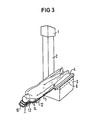
- FIG. 3 shows an X-ray examination table which has a telescopic column 1, on the extendable arm 2 of which a base frame 3 with a patient bed made of a frameless, X-ray-permeable plate 4 for a patient 5 is mounted who carry rails, not shown here, for attaching accessories.
- the bars 6 are shown in their parking positions. If X-rays, in particular oblique images, are to be taken in the area of the head or shoulders of the patient, the bars 6 are pulled out of the underframe 3 with their rails, so that the necessary accessories can be attached to them. This does not affect the recordings.
- FIG. 1 it is shown that the fastening arrangement 7 from one of the contour of the head region of the plate U on fitted bracket exists.
- the bracket has two side parts 8, 9 which are rigidly connected at one end and connected to the other via a tensioning device, for example a flange screw 10.
- the rigid connection which forms a continuation of the bracket, consists of a strip 11 made of a radiopaque material.
- the strip 11 runs in the applied position of the fastening arrangement 7 below the plate 4 and has a shape that corresponds to the plate profile.
- clips 14 are fastened for gripping around the plate 4 (FIG. 2).
- rails 12 for attaching accessories are attached to the side parts.
- the distance between the side parts 8, 9 is dimensioned such that the bracket can be easily pushed onto the head part of the plate 4.
- the flange screw 10 which engages with the side parts 8, 9 via threaded bolts 13, these are pressed against the outer contour of the plate 4, as a result of which the bracket is fastened to the latter.
- the cap screw 10 is rotated in the opposite direction, the side parts 8, 9 diverging.
- the shape of the fastening arrangement leaves the area of the plate 4 which is permeable to X-rays transparent and which is enclosed by the bracket free of materials which interfere with an X-ray image.
- 7 x-ray recordings can be made without any problems in the area of the shoulders or the head of the patient, even when an attachment arrangement is applied.
Landscapes
- Health & Medical Sciences (AREA)
- Life Sciences & Earth Sciences (AREA)
- Engineering & Computer Science (AREA)
- Biomedical Technology (AREA)
- Veterinary Medicine (AREA)
- Public Health (AREA)
- Medical Informatics (AREA)
- General Health & Medical Sciences (AREA)
- Animal Behavior & Ethology (AREA)
- High Energy & Nuclear Physics (AREA)
- Radiology & Medical Imaging (AREA)
- Pathology (AREA)
- Heart & Thoracic Surgery (AREA)
- Molecular Biology (AREA)
- Surgery (AREA)
- Optics & Photonics (AREA)
- Nuclear Medicine, Radiotherapy & Molecular Imaging (AREA)
- Physics & Mathematics (AREA)
- Biophysics (AREA)
- Apparatus For Radiation Diagnosis (AREA)
- Accommodation For Nursing Or Treatment Tables (AREA)
Abstract
Description
- Die Erfindung betrifft eine Befestigungsanordnung für Zubehöre für eine Patientenliege mit einer rahmenlosen, röntgenstrahlendurchlässigen Platte.
- Eine solche Befestigungsanordnung, die an das Kopfende der Patientenliege appliziert ist,ist durch den SIEMENS-Prospekt "KOORDINAT 3D" bekannt. Diese Befestigungsanordnung wird verwendet, wenn im Brust- und Bauchbereich multidirektionale Aufnahmen, d.h. Schrägaufnahmen aus mehreren Richtungen, gemacht werden sollen. Bei einer solchen Rötgenuntersuchung dürfen in dem Bereich keine Zubehöre vorhanden sein, da sie die Aufnahmen verschlechtern und die Handhabung der Geräte stören würden. Die bekannte Befestigungsansordnung besteht aus einer Holzplatte und weist Schienen auf, die auf die röntgenstrahlendurchlässige Platte aufgeschoben werden können. Diese Befestigungsanordnung besitzt auch Löcher zum Applizieren von Zubehören wie z.B. Armstützen, Handgriffen, Steuervorrichtungen, Druckrezeptoren und Behältern für Kochsalzlösung.
- Der Nachteil dieser Befestigungsanordnung besteht. dain, dass sie keine Standardschienen zum Befestigen von Zubehören besitzt. Die ansonsten auf den Standardschienen applizierten Zubehöre müssen daher teilweise neu konstruiert werden, damit sie in den Löchern befestigt werden können. Weiterhin verläuft die bekannte Platte unter dem röntgenstrahlentransparenten Kopfteil der Patientenliege, so dass dieser Bereich bei einer applizierten Platte nicht störungsfrei aufgenommen werden kann.
- Der Erfindung liegt die Aufgabe zugrunde, eine Befestigungsanordnung der eingangs genannten Art zu schaffen, an der Zubehöre mit Standard-Befestigungen appliziert werden und ausserdem auch bei applizierten Befestigungsanordnungen Röntgenaufnahmen in diesem Bereich gemacht werden können.
- Diese Aufgabe ist erfindungsgemäss durch einen der Aussenkontur eines Bereiches der Platte angepassten Bügel, der diese im Randbereich zumindest teilweise umgreift, mindestens eine Spannvorrichtung zum Arretieren des Bügels an der Platte sowie mindestens eine Schiene zur Befestigung des Zubehörs gelöst. Dadurch, dass der Bügel im Randbereich der Patientenliege verläuft, kann auch der vom Bügel umspannte Bereich störungsfrei aufgenommen werden. Ferner können durch die Schiene bzw. die Schienen Zubehöre mit Standardbefestigungen appliziert werden.
- Weitere Vorteile und Einzelheiten der Erfindung ergeben sich aus den Unteransprüchen.
- Die Erfindung ist nachfolgend anhand eines in der Zeichnung dargestellten Ausführungsbeispieles näher erläutert. Es zeigen:
- Fig.1 eine Befestigungsanordnung nach der Erfindung
- Fig.2 einen Schnitt durch eine Befestigungsanordnung gemäss der Schnittlinie II-II von Fig.1 1 und
- Fig.3 eine Perspektivansicht eines Röntgenuntersuchungsgerätes mit einer Befestigungsanordnung nach Fig.1.
- In Fig.3 ist ein Röntgenuntersuchungstisch gezeigt, der eine Teleskopsäule 1 besitzt, an derem ausfahrbaren Arm 2 ein Untergestell 3 mit einer Patientenliege aus einer rahmenlosen, röntgenstrahlendurchlässigen Platte 4 für einen Patienten 5 gelagert ist.Das Untergestell 3 weist in Tischlängsrichtung verschiebbare Balken 6 auf, die hier nicht dargestellte Schienen für die Befestigung von Zubehören tragen. In dieser Figur sind die Balken 6 in ihren Parklagen dargestellt. Wenn im Bereich des Kopfes oder der Schultern des Patienten Röntgenaufnahmen, insbesondere Schrägaufnahmen gemacht werden sollen, werden die Balken 6 mit ihren Schienen aus dem Untergestell 3 herausgezogen, so dass die notwendigen Zubehöre darauf befestigt werden können. Die Aufnahmen werden hierdurch nicht beeinflusst.
- Wenn multidirektionale Aufnahmen im Brust- oder Baubereich des Patienten vorgenommen werden sollen, werden die Balken 6 in das Untergestell 3 hineingeschoben. Die bekannten und daher nicht dargestellten Zubehöre werden nun auf Standardschienen 12 einer später näher beschriebenen Befestigungsanordnung 7, die am Kopfende angebracht wird, befestigt. Der Brust- und Bauchbereich ist nun frei von Balken und Zubehören, so dass einwandfreie Röntgenaufnahmen in beliebigen Winkeln gemacht werden können.
- In Fig.1 ist gezeigt, dass die Befestigungsanordnung 7 aus einem der Kontur des Kopfbereiches der Platte U angepassten Bügel besteht. Der Bügel weist zwei Seitenteile 8,9 auf, die an einem Ende starr und am anderen über eine Spannvorrichtung, z.B. eine Wantschraube 10 miteinander verbunden sind. Die starre Verbindung, die eine Fortsetzung des Bügels bildet, besteht aus einer Leiste 11 aus einem röntgendurchlässigen Material. Die Leiste 11 verläuft in applizierter Lage der Befestigungsanordnung 7 unterhalb der Platte 4 und weist eine Form auf, die dem Plattenprofil entspricht. An den Seitenteilen 8,9 des Bügels sind Klammern 14 zum Umgreifen der Platte 4 befestigt (Fig.2). Ferner sind an den Seitenteilen Schienen 12 für die Befestigung von Zubehören angebracht.
- Der Abstand zwischen den Seitenteilen 8,9 ist so bemessen, dass der Bügel mühelos auf den Kopfteil der Platte 4 aufgeschoben werden kann. Beim Drehen der Wantschraube 10, die über Gewindebolzen 13 mit den Seitenteilen 8,9 in Eingriff steht, werden diese an die Aussenkontur der Platte 4 gedrückt, wodurch der Bügel an dieser befestigt wird. Beim Lösen des Bügels von der Platte 4 wird die Wantschraube 10 in die entgegengesetzte Richtung gedreht, wobei die Seitenteile 8,9 auseinander gehen.
- Die Form der Befestigungsanordnung lässt den vom Bügel umfassten Bereich der röntgenstrahlendurchlässigen Platte 4 frei von eine Röntgenaufnahme störenden Materialien. Dadurch können im Bereich der Schultern bzw. des Kopfes des Patienten auch bei einer applizierten Befestigungsanordnung 7 Röntgenaufnahmen einwandfrei vorgenommen werden.
Claims (7)
Applications Claiming Priority (3)
| Application Number | Priority Date | Filing Date | Title |
|---|---|---|---|
| DE19823236135 DE3236135A1 (de) | 1982-09-29 | 1982-09-29 | Befestigungsanordnung fuer zubehoere fuer eine patientenliege |
| DE3236135 | 1982-09-29 | ||
| DE8227385U DE8227385U1 (de) | 1982-09-29 | 1982-09-29 | Befestigungsanordnung für Zubehöre für eine Patientenliege |
Publications (3)
| Publication Number | Publication Date |
|---|---|
| EP0104591A2 true EP0104591A2 (de) | 1984-04-04 |
| EP0104591A3 EP0104591A3 (en) | 1985-05-15 |
| EP0104591B1 EP0104591B1 (de) | 1988-05-18 |
Family
ID=40130573
Family Applications (1)
| Application Number | Title | Priority Date | Filing Date |
|---|---|---|---|
| EP83109335A Expired EP0104591B1 (de) | 1982-09-29 | 1983-09-20 | Befestigungsanordnung für Zubehöre für eine Patientenliege |
Country Status (3)
| Country | Link |
|---|---|
| US (1) | US4506872A (de) |
| EP (1) | EP0104591B1 (de) |
| DE (2) | DE3236135A1 (de) |
Cited By (7)
| Publication number | Priority date | Publication date | Assignee | Title |
|---|---|---|---|---|
| WO1999011176A1 (en) * | 1997-09-03 | 1999-03-11 | Ohio Medical Instrument Company, Inc. | Radiolucent table extension assembly |
| US6003174A (en) * | 1997-09-03 | 1999-12-21 | Kantrowitz; Allen | Radiolucent table extension and method |
| US6557195B2 (en) | 1999-02-11 | 2003-05-06 | Ohio Medical Instruments Company, Inc. | Hinged adaptor assembly for radiolucent table extension |
| US6584630B1 (en) | 2000-04-06 | 2003-07-01 | Ohio Medical Instrument Company, Inc. | Radiolucent surgical table extension assembly and method |
| US6813788B2 (en) | 2000-04-06 | 2004-11-09 | Schaerer Mayfield Usa, Inc. | Variable length radiolucent surgical table extension |
| WO2021165331A1 (en) * | 2020-02-19 | 2021-08-26 | Koninklijke Philips N.V. | Temporarily attachment of medical equipment to a subject support |
| EP3936051A1 (de) * | 2020-07-07 | 2022-01-12 | Koninklijke Philips N.V. | Vorübergehende befestigung von medizinischen geräten an einer personentrage |
Families Citing this family (53)
| Publication number | Priority date | Publication date | Assignee | Title |
|---|---|---|---|---|
| JPS6041955A (ja) * | 1983-08-19 | 1985-03-05 | 株式会社東芝 | Ct用寝台昇降装置 |
| EP0221325B1 (de) * | 1985-10-09 | 1990-07-25 | Siemens Aktiengesellschaft | Lithotripsie-Einheit |
| US4715591A (en) * | 1986-04-10 | 1987-12-29 | Picker International, Inc. | Patient support for radiation imaging |
| US4880222A (en) * | 1986-04-10 | 1989-11-14 | Picker International, Inc. | Patient support for radiation imaging |
| US4768241A (en) * | 1987-02-24 | 1988-09-06 | Beney Daniel R | Self contained, mobile intensive care bed structure |
| JP3577114B2 (ja) * | 1994-09-20 | 2004-10-13 | 株式会社東芝 | シンチレーションカメラ |
| US6076208A (en) * | 1997-07-14 | 2000-06-20 | Hill-Rom, Inc. | Surgical stretcher |
| US6199233B1 (en) * | 1998-04-24 | 2001-03-13 | Allen Kantrowitz | Radiolucent table extension assembly |
| US6456684B1 (en) | 1999-07-23 | 2002-09-24 | Inki Mun | Surgical scanning system and process for use thereof |
| DE19955363C2 (de) * | 1999-11-17 | 2002-10-24 | Maquet Gmbh & Co Kg | Befestigungssystem für Zubehörteile an einem Operationstisch |
| DE20016235U1 (de) * | 2000-09-18 | 2000-12-14 | Siemens AG, 80333 München | Patientenlagerungstisch für chirurgische und angiographische Anwendungen |
| US6578215B1 (en) | 2000-09-29 | 2003-06-17 | Hill-Rom Services, Inc. | Surgery stretcher |
| US7020917B1 (en) * | 2001-03-12 | 2006-04-04 | Steris Corporation | Radiolucent surgical table with low shadow accessory interface profile |
| USD461900S1 (en) | 2001-06-19 | 2002-08-20 | The Brewer Company, Llc | Top for a medical examination table |
| USD458780S1 (en) | 2001-06-19 | 2002-06-18 | The Brewer Company, Llc | Drawer front face |
| US6550084B2 (en) | 2001-06-19 | 2003-04-22 | The Brewer Company, Llc | Medical examination table step |
| USD463861S1 (en) | 2001-06-19 | 2002-10-01 | The Brewer Company, Llc | Stirrup for a medical examination table |
| USD461899S1 (en) | 2001-06-19 | 2002-08-20 | The Brewer Company, Llc | Medical examination table |
| USD462674S1 (en) | 2001-06-19 | 2002-09-10 | The Brewer Company, Llc | Medical examination table cabinet |
| USD507905S1 (en) | 2003-09-29 | 2005-08-02 | The Brewer Company, Llc | Lifting column |
| USD496462S1 (en) | 2003-09-29 | 2004-09-21 | The Brewer Company, Llc | Medical examination table |
| US20050066861A1 (en) * | 2003-09-29 | 2005-03-31 | The Brewer Company, Llc | Lifting column for a medical examination table |
| US7093313B2 (en) * | 2003-09-29 | 2006-08-22 | The Brewer Company, Llc | Headrest linkage |
| US7083355B2 (en) * | 2003-09-29 | 2006-08-01 | The Brewer Company, Llc | Stirrup support indexer for a medical examination table |
| US7350249B2 (en) * | 2003-09-29 | 2008-04-01 | The Brewer Company, Llc | Leg rest and kneeler assembly for a medical examination table |
| US7210180B2 (en) * | 2003-10-20 | 2007-05-01 | Malcolm Roger J | Surgical table width extension and angularly orientable attachment |
| US8905637B2 (en) * | 2004-07-30 | 2014-12-09 | Neurologica Corp. | X-ray transparent bed and gurney extender for use with mobile computerized tomography (CT) imaging systems |
| US7736056B2 (en) | 2004-07-30 | 2010-06-15 | Neurologica Corp. | X-ray transparent bed and gurney extender for use with mobile computerized tomography (CT) imaging systems |
| US20060054395A1 (en) * | 2004-08-17 | 2006-03-16 | Horizon Veterinary Services, Inc. | Telescoping motorized lift platform |
| USD535395S1 (en) * | 2004-09-15 | 2007-01-16 | Bionix Development Corporation | Patient positioning frame |
| USD535024S1 (en) * | 2004-09-15 | 2007-01-09 | Bionix Development Corporation | Patient positioning frame |
| USD536094S1 (en) * | 2004-09-15 | 2007-01-30 | Bionix Development Corporation | Patient positioning frame |
| US7520007B2 (en) * | 2004-11-10 | 2009-04-21 | Allen Medical Systems, Inc. | Accessory rail clamp with latch and lock mechanisms |
| US7520008B2 (en) * | 2004-11-10 | 2009-04-21 | Allen Medical Systems | Surgical table extension |
| US7669262B2 (en) * | 2004-11-10 | 2010-03-02 | Allen Medical Systems, Inc. | Accessory frame for spinal surgery |
| USD574960S1 (en) | 2005-07-28 | 2008-08-12 | Parrish Vanessa B | Medical examination table top |
| USD535544S1 (en) | 2005-07-28 | 2007-01-23 | The Brewer Company, Llc | Grab bar |
| USD569520S1 (en) | 2005-07-28 | 2008-05-20 | Debraal Jack A | Medical examination table cabinet |
| US9038216B2 (en) | 2005-07-28 | 2015-05-26 | The Brewer Company, Llc | Medical examination table |
| USD574959S1 (en) | 2005-07-28 | 2008-08-12 | Debraal Jack A | Medical examination table |
| US7513000B2 (en) | 2005-07-28 | 2009-04-07 | The Brewer Company, Llc | Medical examination table |
| US7386899B2 (en) * | 2005-09-14 | 2008-06-17 | Midmark Corporation | Medical examination table with pullout step |
| WO2007133723A2 (en) * | 2006-05-12 | 2007-11-22 | Neurologica Corp. | X-ray transparent bed and gurney extender for use with mobile computerized tomography (ct) imaging systems |
| JP2010536535A (ja) * | 2007-08-24 | 2010-12-02 | アレン メディカル システムズ インコーポレイテッド | 手術台アクセサリプラットフォーム |
| WO2010051303A1 (en) * | 2008-10-28 | 2010-05-06 | Allen Medical Systems, Inc. | Prone and laterally angled surgical device and method |
| US8833707B2 (en) | 2010-07-15 | 2014-09-16 | Allen Medical Systems, Inc. | Disposable urology drainage bag |
| US9498397B2 (en) | 2012-04-16 | 2016-11-22 | Allen Medical Systems, Inc. | Dual column surgical support system |
| US9161875B2 (en) | 2012-09-07 | 2015-10-20 | Allen Medical Systems, Inc. | Multi-axis joint for a spar of a limb holder |
| US9655793B2 (en) | 2015-04-09 | 2017-05-23 | Allen Medical Systems, Inc. | Brake release mechanism for surgical table |
| US10010460B2 (en) | 2015-06-01 | 2018-07-03 | The United States Of America, As Represented By The Secretary Of The Army | Surgical rail apparatus for litter |
| US10898394B2 (en) | 2015-06-01 | 2021-01-26 | The Government Of The United States, As Represented By The Secretary Of The Army | Surgical rail apparatus for litter |
| US11213448B2 (en) | 2017-07-31 | 2022-01-04 | Allen Medical Systems, Inc. | Rotation lockout for surgical support |
| US11202731B2 (en) | 2018-02-28 | 2021-12-21 | Allen Medical Systems, Inc. | Surgical patient support and methods thereof |
Family Cites Families (11)
| Publication number | Priority date | Publication date | Assignee | Title |
|---|---|---|---|---|
| US2465781A (en) * | 1946-04-12 | 1949-03-29 | Wallace B Creamer | Embalmer's aid |
| US2550306A (en) * | 1947-04-18 | 1951-04-24 | William J Soper | Conveyer service tray for operating tables |
| US2713530A (en) * | 1954-04-20 | 1955-07-19 | George E Chisholm | Attachment for tables |
| FR1150690A (fr) * | 1955-04-09 | 1958-01-16 | Portique d'accouchement et de gynécologie | |
| GB1143393A (en) * | 1965-04-01 | 1969-02-19 | Isaac Henry John Bourne | Headrest for car and like seats |
| US3381684A (en) * | 1965-09-29 | 1968-05-07 | Robert T. Anderson | Therapeutic apparatus for supporting portions of the body |
| FR2184165A5 (de) * | 1972-05-09 | 1973-12-21 | Veller Et Cie Ets | |
| US4064401A (en) * | 1976-02-04 | 1977-12-20 | Danny Alden Marden | Headholder assembly |
| DE2759079C2 (de) * | 1977-12-30 | 1983-04-07 | Siemens AG, 1000 Berlin und 8000 München | Untersuchungstisch für ein urologisches Röntgenuntersuchungsgerät |
| US4346298A (en) * | 1981-03-02 | 1982-08-24 | Dixit Jagannath K | Automatic air pillow for diagnostic X-ray machine |
| US4391438A (en) * | 1981-06-12 | 1983-07-05 | Heffington Jr Charles A | Patient support attachment for surgical tables |
-
1982
- 1982-09-29 DE DE19823236135 patent/DE3236135A1/de not_active Withdrawn
- 1982-09-29 DE DE8227385U patent/DE8227385U1/de not_active Expired
-
1983
- 1983-08-16 US US06/523,591 patent/US4506872A/en not_active Expired - Fee Related
- 1983-09-20 EP EP83109335A patent/EP0104591B1/de not_active Expired
Cited By (7)
| Publication number | Priority date | Publication date | Assignee | Title |
|---|---|---|---|---|
| WO1999011176A1 (en) * | 1997-09-03 | 1999-03-11 | Ohio Medical Instrument Company, Inc. | Radiolucent table extension assembly |
| US6003174A (en) * | 1997-09-03 | 1999-12-21 | Kantrowitz; Allen | Radiolucent table extension and method |
| US6557195B2 (en) | 1999-02-11 | 2003-05-06 | Ohio Medical Instruments Company, Inc. | Hinged adaptor assembly for radiolucent table extension |
| US6584630B1 (en) | 2000-04-06 | 2003-07-01 | Ohio Medical Instrument Company, Inc. | Radiolucent surgical table extension assembly and method |
| US6813788B2 (en) | 2000-04-06 | 2004-11-09 | Schaerer Mayfield Usa, Inc. | Variable length radiolucent surgical table extension |
| WO2021165331A1 (en) * | 2020-02-19 | 2021-08-26 | Koninklijke Philips N.V. | Temporarily attachment of medical equipment to a subject support |
| EP3936051A1 (de) * | 2020-07-07 | 2022-01-12 | Koninklijke Philips N.V. | Vorübergehende befestigung von medizinischen geräten an einer personentrage |
Also Published As
| Publication number | Publication date |
|---|---|
| EP0104591B1 (de) | 1988-05-18 |
| DE8227385U1 (de) | 1985-12-19 |
| DE3236135A1 (de) | 1984-03-29 |
| US4506872A (en) | 1985-03-26 |
| EP0104591A3 (en) | 1985-05-15 |
Similar Documents
| Publication | Publication Date | Title |
|---|---|---|
| EP0104591B1 (de) | Befestigungsanordnung für Zubehöre für eine Patientenliege | |
| DE69315220T2 (de) | Röntgenstrahldurchlässige kopfstütze | |
| EP0973476A1 (de) | Operationseinrichtung | |
| DE3218328A1 (de) | Operationstisch | |
| DE2352472B2 (de) | Schmutzfaenger | |
| DE102013111523A1 (de) | Röntgenoptimierte Vorrichtung zum Lagern eines Patienten | |
| DE3010421A1 (de) | Instrument zum halten und einsetzen der tibiaplateaus fuer eine kniegelenk-gleitflaechenprothese | |
| EP1335692B1 (de) | Anordnung zur halterung von zubehörteilen an einer patientenlagerfläche | |
| EP0592825A2 (de) | Höhenverstellbarer Tisch | |
| DE3114382A1 (de) | Schuettlerloser selbstfahrender maehdrescher | |
| EP0498255B1 (de) | Strahlenuntersuchungsgerät für Brustuntersuchungen | |
| DE3437203C2 (de) | ||
| DE69811567T2 (de) | An eine Eisenbahnschiene zu befestigende Vorrichtung, so dass Mittel um die Eisenbahn abzuschirmen mit einer Vielzahl von Vorrichtungen verbunden werden können | |
| DE8814203U1 (de) | Röntgenuntersuchungseinrichtung | |
| DE2342365A1 (de) | Schmutzfaenger | |
| DE4328852A1 (de) | Lösbar an einem Kraftfahrzeugdach festlegbare Tragstrebenhalterung | |
| DE2938261A1 (de) | Patienten-liegeplatte fuer roentgendiagnostische zwecke, insbesondere fuer angiografien | |
| DE102011051977A1 (de) | Board | |
| DE3222332A1 (de) | Roentgenuntersuchungstisch | |
| CH670200A5 (de) | ||
| DE29708363U1 (de) | Tragevorrichtung für medizinische Geräte | |
| DE29819028U1 (de) | Halteeinrichtung für Personen in Fahrzeugen des öffentlichen Personenverkehrs | |
| DE102004017849A1 (de) | Röntgendiagnostikgerät für Mammographieuntersuchungen | |
| DE10338051A1 (de) | Vergrößerungstisch und Röntgendiagnostikgerät für Mammographieuntersuchungen | |
| DE1922131U (de) | Stuetzgestell fuer krankentragen in retungsfahrzeugen. |
Legal Events
| Date | Code | Title | Description |
|---|---|---|---|
| PUAI | Public reference made under article 153(3) epc to a published international application that has entered the european phase |
Free format text: ORIGINAL CODE: 0009012 |
|
| AK | Designated contracting states |
Designated state(s): DE FR SE |
|
| 17P | Request for examination filed |
Effective date: 19841221 |
|
| PUAL | Search report despatched |
Free format text: ORIGINAL CODE: 0009013 |
|
| AK | Designated contracting states |
Designated state(s): DE FR SE |
|
| 17Q | First examination report despatched |
Effective date: 19870115 |
|
| GRAA | (expected) grant |
Free format text: ORIGINAL CODE: 0009210 |
|
| AK | Designated contracting states |
Kind code of ref document: B1 Designated state(s): DE FR SE |
|
| REF | Corresponds to: |
Ref document number: 3376622 Country of ref document: DE Date of ref document: 19880623 |
|
| ET | Fr: translation filed | ||
| PLBE | No opposition filed within time limit |
Free format text: ORIGINAL CODE: 0009261 |
|
| STAA | Information on the status of an ep patent application or granted ep patent |
Free format text: STATUS: NO OPPOSITION FILED WITHIN TIME LIMIT |
|
| 26N | No opposition filed | ||
| EAL | Se: european patent in force in sweden |
Ref document number: 83109335.6 |
|
| PGFP | Annual fee paid to national office [announced via postgrant information from national office to epo] |
Ref country code: SE Payment date: 19950912 Year of fee payment: 13 |
|
| PGFP | Annual fee paid to national office [announced via postgrant information from national office to epo] |
Ref country code: FR Payment date: 19950919 Year of fee payment: 13 |
|
| PGFP | Annual fee paid to national office [announced via postgrant information from national office to epo] |
Ref country code: DE Payment date: 19951116 Year of fee payment: 13 |
|
| PG25 | Lapsed in a contracting state [announced via postgrant information from national office to epo] |
Ref country code: SE Effective date: 19960921 |
|
| PG25 | Lapsed in a contracting state [announced via postgrant information from national office to epo] |
Ref country code: FR Effective date: 19960930 |
|
| PG25 | Lapsed in a contracting state [announced via postgrant information from national office to epo] |
Ref country code: DE Effective date: 19970603 |
|
| EUG | Se: european patent has lapsed |
Ref document number: 83109335.6 |
|
| REG | Reference to a national code |
Ref country code: FR Ref legal event code: ST |
|
| REG | Reference to a national code |
Ref country code: FR Ref legal event code: ST |