EP0103974B1 - Link and flight assembly for blast treatment apparatus - Google Patents
Link and flight assembly for blast treatment apparatus Download PDFInfo
- Publication number
- EP0103974B1 EP0103974B1 EP83304623A EP83304623A EP0103974B1 EP 0103974 B1 EP0103974 B1 EP 0103974B1 EP 83304623 A EP83304623 A EP 83304623A EP 83304623 A EP83304623 A EP 83304623A EP 0103974 B1 EP0103974 B1 EP 0103974B1
- Authority
- EP
- European Patent Office
- Prior art keywords
- flight
- link
- blast
- links
- backer bar
- Prior art date
- Legal status (The legal status is an assumption and is not a legal conclusion. Google has not performed a legal analysis and makes no representation as to the accuracy of the status listed.)
- Expired
Links
Images

Classifications
-
- B—PERFORMING OPERATIONS; TRANSPORTING
- B24—GRINDING; POLISHING
- B24C—ABRASIVE OR RELATED BLASTING WITH PARTICULATE MATERIAL
- B24C3/00—Abrasive blasting machines or devices; Plants
- B24C3/18—Abrasive blasting machines or devices; Plants essentially provided with means for moving workpieces into different working positions
- B24C3/26—Abrasive blasting machines or devices; Plants essentially provided with means for moving workpieces into different working positions the work being supported by barrel cages, i.e. tumblers; Gimbal mountings therefor
Definitions
- This invention relates to a machine for cleaning the surfaces of articles, such as metal castings and the like, by throwing abrasive at the surfaces of the articles as they are tumbled about in a cabinet. It relates more particularly to a means for conveying the articles into and out of the cabinet and for providing for a continuous tumbling action within the machine during operation.
- the invention is related to a centrifugal blasting machine of the type described in the Peik Patent No. 2,104,055.
- such machines comprise a housing completely enclosing a conveying means formed of a plurality of flights which extend crosswise between endless chains for travel about a predetermined path with the flights preferably in overlapping relation at their edges to form an endless, horizontally disposed belt on which the work or articles to be cleaned are supported.
- the flights of the belt travel between a driving sprocket and a guide roller spaced forwardly and below the sprocket.
- a pair of spaced circular drums mounted for rotational movement about a horizontal axis between the sprockets and rollers with a peripheral portion of the drum extending rearwardly and below the sprocket and rearwardly and below the roller whereby the upper flight of the belt travels horizontally and in a downward direction beyond the roller and upwardly and in a forwardly direction in advance of the sprocket.
- the area between the drums is substantially completely enclosed by the belt and other portions of the housing including a doorway through which access may be had to the top flight of the conveyor belt for loading and unloading the machine.
- One or more centrifugal blast wheels for throwing abrasive particles into the housing and onto the work are mounted on the housing with suitable attachments for feeding and driving the units. A detailed description thereof will not be made since they form no part of this invention and are adequately described in the aforementioned issued patent.
- Patent No. 3,079,735 to Freeman which provides a continuous conveyor which is free of openings between the flights by virtue of a flexible sealing element provided for that purpose.
- the flights are formed of relatively expensive materials, such as manganese, which are selected for their resistance to blast treatment. Such materials, of course, are relatively expensive and it is desirable, therefore to minimize the use of such material to the extent practical.
- the Freeman device employs a system for joining the link and flight in which mounting holes are provided in the blast resistant portion of the flight.
- a connecting mechanism in the form of a reinforcing bar attached to the link, is then secured to the flight bar by means of bolts which are received in the mounting holes in the blast resistant portion.
- the bolts used In-order to obtain maximum life from the flight, it is necessary that the bolts used also be of blast resistant material. Forming counter sunk holes in the blast resistant portion of the flight and providing blast resistant bolts significantly increases the cost of the flights.
- US-A-3691690 there is disclosed a link and flight assembly for a blast cabinet in which the light comprises a first element or slat capped with a wear resistant material such as cast manganese steel with a backer or stiffener bar secured to the rear of the first element or slat.
- a link and flight assembly for a blast cabinet conveyor comprising a flight having a first element thereof formed of material which is highly resistant to blast treatment and a backer bar secured to the rear of said first element; a pair of links including means for interengaging other links to form a conveyor belt of link and flight assemblies and means for securing said links to both ends of said flight characterised in that said backer bar is secured in perpendicular relation to said first element to define a generally T-configuration and is substantially longitudinally co-terminous with the first element with said securing means being connected only to said backer bar at the ends thereof, the links, backer bar and securing means being formed of lower cost, less blast resistant materials than said first element.
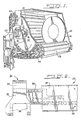
- FIG. 1 illustration is made of the conveyor and drum portion of the blast machine comprising a pair of spaced drums 10 and 12 having liner plates 14 secured onto the inner faces thereof for purposes of protecting the drums against wear by the abrasive materials thrown at high velocity into the space between the drums.
- the drums are mounted on shafts 16 which are secured at their ends in journals 18 fixed to the frame plate 20 of the machine for enabling rotational movement of the drums about a horizontal axis.
- the flight 23 is T-shaped in cross-section and includes a blast resistant surface 24 formed of a material such as manganese and a backer bar 26 formed of less expensive material, such as mild steel.
- the backer bar 26 is welded to the flight 24 to form the T-shaped configuration.
- the backer bar may be centrally located on the rear face of the blast surface 24 or offset somewhat from the center in order to provide clearance and proper sealing during operation. This aspect of the flight will vary according to the size and design requirements of the machine.
- the blast resistant surface 24 has provided therein a number of drain holes 28 which permit abrasive to exit from the blast cabinet to be recycled to the blasting wheels for further treatment.
- the backer bar 26 includes a number of mounting holes 29 which are drilled therethrough to permit the flight assembly 23 to be secured to a link assembly 30.
- the link assembly includes a link 32 having the usual apertures 34 and 36 at each end thereof dimensioned to interengage like elements of other flight and link assemblies by means of link pins, etc.
- a mounting arm 38 preferably integrally formed with the link element 32, extends transversely from the link and terminates in a generally rectangular mounting plate 40.
- the mounting plate is provided with holes corresponding to those provided on the backer bar 26 whereby bolts 42 can secure the assemblies together.
- the blast resistant surface 24, subjected to the abrasive treatment plays no part in securing the flight assembly 23 to the link assembly 30. Rather securing is accomplished by bolting mounting plate 40 of the arm 38 to the backer bar 26.
- This arrangement achieves a significant advantage in that mounting bolt heads have been eliminated on the face of the flight which have proven to be a point of high wear.
- Only the blast resistant surface 24 need be of manganese or similar material while the backer bar 26, which is not subjected to blast treatment, may be of less expensive mild steel or the like. Further, since the bolting occurs on the backer bar, long life fasteners, of manganese or similar materials, need not be used.
- the embodiment results in a link and flight assembly which has improved wear characteristics and which is significantly lower in cost because of the ability to use less costly bolts for joining the elements and the eliminating of mounting holes in blast resistant materials.
- Operation of the blast cabinet is via a driving motor which turns the sprocket 44.
- the lugs of the sprocket which are enmeshed with the undercuts in the links cause the link chain to travel about the sprocket 44 and the roller 46.
- the flights move with the links to provide a continuously travelling, substantially continuous support on which the work is carried.
Applications Claiming Priority (2)
| Application Number | Priority Date | Filing Date | Title |
|---|---|---|---|
| US06/410,619 US4476655A (en) | 1982-08-23 | 1982-08-23 | Link and flight assembly for blast treatment apparatus |
| US410619 | 1999-10-01 |
Publications (2)
| Publication Number | Publication Date |
|---|---|
| EP0103974A1 EP0103974A1 (en) | 1984-03-28 |
| EP0103974B1 true EP0103974B1 (en) | 1987-06-24 |
Family
ID=23625505
Family Applications (1)
| Application Number | Title | Priority Date | Filing Date |
|---|---|---|---|
| EP83304623A Expired EP0103974B1 (en) | 1982-08-23 | 1983-08-10 | Link and flight assembly for blast treatment apparatus |
Country Status (8)
| Country | Link |
|---|---|
| US (1) | US4476655A (ko) |
| EP (1) | EP0103974B1 (ko) |
| JP (1) | JPS5981062A (ko) |
| AU (1) | AU1802883A (ko) |
| BR (1) | BR8304528A (ko) |
| CA (1) | CA1217055A (ko) |
| DE (1) | DE3372187D1 (ko) |
| IN (1) | IN158704B (ko) |
Cited By (1)
| Publication number | Priority date | Publication date | Assignee | Title |
|---|---|---|---|---|
| DE102007027764B3 (de) * | 2007-06-16 | 2008-06-19 | Rösler, Matthias | Muldenband-Strahlanlage zum Strahlen von Werkstücken |
Families Citing this family (11)
| Publication number | Priority date | Publication date | Assignee | Title |
|---|---|---|---|---|
| DE3839380A1 (de) * | 1988-11-22 | 1990-05-23 | Linde Ag | Bandfoerderanlage mit einem als geflechtgurt ausgebildeten foerderband |
| US5107629A (en) * | 1989-11-09 | 1992-04-28 | The Celotex Corporation | Texturing of acoustical mineral fiberboard with wheel blast machine |
| US5782677A (en) * | 1997-01-14 | 1998-07-21 | Kanouse; Richard C. | Continuous process blast mill for finishing cast metal parts |
| US6983901B2 (en) * | 2003-09-09 | 2006-01-10 | House Of Metals Company Limited | Method for recycling aluminum alloy wheels |
| US20060157325A1 (en) * | 2005-01-12 | 2006-07-20 | Mat Loutzenheiser | Link and flight assembly for an abrasive blast machine |
| JP2014039960A (ja) * | 2010-12-22 | 2014-03-06 | Sintokogio Ltd | ショット処理装置 |
| US9242251B2 (en) | 2013-01-30 | 2016-01-26 | Wheelabrator Group, Inc. | Magnetic separator with dynamic baffle system |
| US10752446B2 (en) * | 2015-09-25 | 2020-08-25 | Habasit Ag | Hybrid modular belt |
| JP2022535252A (ja) * | 2019-06-04 | 2022-08-05 | ハウス オブ メタルズ カンパニー リミテッド | 表面組成と内部組成の差異を考慮して廃棄金属バッチ組成を決定するための方法およびシステム |
| WO2021003554A1 (en) | 2019-07-09 | 2021-01-14 | House Of Metals Company Limited | Method and system for estimating waste metal batch composition |
| US11761056B2 (en) | 2020-06-17 | 2023-09-19 | House Of Metals Company Limited | Systems and methods for recycling waste metal pieces using shot blasting and shot removal |
Citations (2)
| Publication number | Priority date | Publication date | Assignee | Title |
|---|---|---|---|---|
| US2204636A (en) * | 1938-09-24 | 1940-06-18 | American Foundry Equip Co | Apparatus for treating metal articles |
| US2716310A (en) * | 1952-11-28 | 1955-08-30 | Pangborn Corp | Blasting apparatus |
Family Cites Families (8)
| Publication number | Priority date | Publication date | Assignee | Title |
|---|---|---|---|---|
| US1882443A (en) * | 1929-05-28 | 1932-10-11 | American Foundry Equip Co | Tumbling mill |
| US2104055A (en) * | 1933-08-23 | 1938-01-04 | American Foundry Equip Co | Abrading apparatus |
| US2305451A (en) * | 1940-05-17 | 1942-12-15 | American Foundry Equip Co | Apparatus for treating metal articles |
| US2563084A (en) * | 1948-05-01 | 1951-08-07 | American Wheelabrator & Equipm | Continuous tumbling mill |
| US2909012A (en) * | 1957-01-28 | 1959-10-20 | Wheelabrator Corp | Link and flight bar assembly in a blasting machine |
| US3048947A (en) * | 1959-07-23 | 1962-08-14 | Pangborn Corp | Abrasive blasting apparatus |
| US3079735A (en) * | 1961-03-24 | 1963-03-05 | Bell Internat Corp | Link and flight bar assembly |
| US3691690A (en) * | 1970-10-16 | 1972-09-19 | Carborundum Co | Abrasive blast cleaning arrangement |
-
1982
- 1982-08-23 US US06/410,619 patent/US4476655A/en not_active Expired - Lifetime
-
1983
- 1983-08-10 EP EP83304623A patent/EP0103974B1/en not_active Expired
- 1983-08-10 DE DE8383304623T patent/DE3372187D1/de not_active Expired
- 1983-08-16 AU AU18028/83A patent/AU1802883A/en not_active Abandoned
- 1983-08-22 JP JP58151762A patent/JPS5981062A/ja active Pending
- 1983-08-22 BR BR8304528A patent/BR8304528A/pt unknown
- 1983-08-22 CA CA000435078A patent/CA1217055A/en not_active Expired
- 1983-08-23 IN IN1032/CAL/83A patent/IN158704B/en unknown
Patent Citations (2)
| Publication number | Priority date | Publication date | Assignee | Title |
|---|---|---|---|---|
| US2204636A (en) * | 1938-09-24 | 1940-06-18 | American Foundry Equip Co | Apparatus for treating metal articles |
| US2716310A (en) * | 1952-11-28 | 1955-08-30 | Pangborn Corp | Blasting apparatus |
Cited By (1)
| Publication number | Priority date | Publication date | Assignee | Title |
|---|---|---|---|---|
| DE102007027764B3 (de) * | 2007-06-16 | 2008-06-19 | Rösler, Matthias | Muldenband-Strahlanlage zum Strahlen von Werkstücken |
Also Published As
| Publication number | Publication date |
|---|---|
| DE3372187D1 (en) | 1987-07-30 |
| IN158704B (ko) | 1987-01-10 |
| BR8304528A (pt) | 1984-04-03 |
| US4476655A (en) | 1984-10-16 |
| CA1217055A (en) | 1987-01-27 |
| EP0103974A1 (en) | 1984-03-28 |
| JPS5981062A (ja) | 1984-05-10 |
| AU1802883A (en) | 1984-03-01 |
Similar Documents
| Publication | Publication Date | Title |
|---|---|---|
| EP0103974B1 (en) | Link and flight assembly for blast treatment apparatus | |
| AU2003204713B2 (en) | A self-propelled articulated conveyor system | |
| US5782677A (en) | Continuous process blast mill for finishing cast metal parts | |
| US2563084A (en) | Continuous tumbling mill | |
| KR100762438B1 (ko) | 부착물 자동제거식 버켓 엘리베이터 | |
| US2909012A (en) | Link and flight bar assembly in a blasting machine | |
| US3079735A (en) | Link and flight bar assembly | |
| Fruchtbaum | Bucket Elevators | |
| EP0683120B1 (en) | Conveyor for continuous haulage system | |
| US2724929A (en) | Work blasting equipment | |
| WO2006076429A1 (en) | Link and flight assembly for an abrasive blast machine | |
| JP4608067B2 (ja) | ベルト搬送装置 | |
| US4319624A (en) | Cleaning machine for castings | |
| US2806683A (en) | Dislodging and disintegrating mechanism for a continuous miner | |
| JP3647559B2 (ja) | 自走式ふるい機 | |
| US3691690A (en) | Abrasive blast cleaning arrangement | |
| US3286816A (en) | Bucket elevator | |
| CN211618965U (zh) | 一种矿用皮带输送装置 | |
| US3378133A (en) | Chain and flight assembly for self-loading scrapers | |
| GB865217A (en) | Improvements in or relating to machines for throwing abrasive particles at high velocity onto surfaces | |
| CN218017931U (zh) | 一种抛丸机防打滑钢塑履带 | |
| KR100391554B1 (ko) | 컨베이어 벨트 시스템 | |
| JPH08143137A (ja) | ベルトコンベア落鉱処理方法 | |
| CA2278620C (en) | Device for the controlled cooling of hot-briquetted directly reduced iron sponge | |
| JPH07102474B2 (ja) | 空缶の圧潰処理装置 |
Legal Events
| Date | Code | Title | Description |
|---|---|---|---|
| PUAI | Public reference made under article 153(3) epc to a published international application that has entered the european phase |
Free format text: ORIGINAL CODE: 0009012 |
|
| AK | Designated contracting states |
Designated state(s): BE DE FR GB |
|
| 17P | Request for examination filed |
Effective date: 19840601 |
|
| GRAA | (expected) grant |
Free format text: ORIGINAL CODE: 0009210 |
|
| AK | Designated contracting states |
Kind code of ref document: B1 Designated state(s): BE DE FR GB |
|
| REF | Corresponds to: |
Ref document number: 3372187 Country of ref document: DE Date of ref document: 19870730 |
|
| ET | Fr: translation filed | ||
| BECN | Be: change of holder's name |
Effective date: 19870624 |
|
| PLBE | No opposition filed within time limit |
Free format text: ORIGINAL CODE: 0009261 |
|
| STAA | Information on the status of an ep patent application or granted ep patent |
Free format text: STATUS: NO OPPOSITION FILED WITHIN TIME LIMIT |
|
| RAP2 | Party data changed (patent owner data changed or rights of a patent transferred) |
Owner name: SIGNAL APPLIED TECHNOLOGIES INC. |
|
| 26N | No opposition filed | ||
| REG | Reference to a national code |
Ref country code: GB Ref legal event code: 732 |
|
| REG | Reference to a national code |
Ref country code: FR Ref legal event code: TP |
|
| PGFP | Annual fee paid to national office [announced via postgrant information from national office to epo] |
Ref country code: GB Payment date: 19990804 Year of fee payment: 17 |
|
| PGFP | Annual fee paid to national office [announced via postgrant information from national office to epo] |
Ref country code: FR Payment date: 19990810 Year of fee payment: 17 |
|
| PGFP | Annual fee paid to national office [announced via postgrant information from national office to epo] |
Ref country code: DE Payment date: 19990816 Year of fee payment: 17 |
|
| PGFP | Annual fee paid to national office [announced via postgrant information from national office to epo] |
Ref country code: BE Payment date: 19991013 Year of fee payment: 17 |
|
| PG25 | Lapsed in a contracting state [announced via postgrant information from national office to epo] |
Ref country code: GB Free format text: LAPSE BECAUSE OF NON-PAYMENT OF DUE FEES Effective date: 20000810 |
|
| PG25 | Lapsed in a contracting state [announced via postgrant information from national office to epo] |
Ref country code: BE Free format text: LAPSE BECAUSE OF NON-PAYMENT OF DUE FEES Effective date: 20000831 |
|
| BERE | Be: lapsed |
Owner name: SIGNAL APPLIED TECHNOLOGIES INC. Effective date: 20000831 |
|
| GBPC | Gb: european patent ceased through non-payment of renewal fee |
Effective date: 20000810 |
|
| PG25 | Lapsed in a contracting state [announced via postgrant information from national office to epo] |
Ref country code: FR Free format text: LAPSE BECAUSE OF NON-PAYMENT OF DUE FEES Effective date: 20010430 |
|
| PG25 | Lapsed in a contracting state [announced via postgrant information from national office to epo] |
Ref country code: DE Free format text: LAPSE BECAUSE OF NON-PAYMENT OF DUE FEES Effective date: 20010501 |
|
| REG | Reference to a national code |
Ref country code: FR Ref legal event code: ST |