EP0103778A2 - Broyeur à marteaux - Google Patents
Broyeur à marteaux Download PDFInfo
- Publication number
- EP0103778A2 EP0103778A2 EP83108411A EP83108411A EP0103778A2 EP 0103778 A2 EP0103778 A2 EP 0103778A2 EP 83108411 A EP83108411 A EP 83108411A EP 83108411 A EP83108411 A EP 83108411A EP 0103778 A2 EP0103778 A2 EP 0103778A2
- Authority
- EP
- European Patent Office
- Prior art keywords
- grate
- hammer
- outlet
- rotor
- outlet grate
- Prior art date
- Legal status (The legal status is an assumption and is not a legal conclusion. Google has not performed a legal analysis and makes no representation as to the accuracy of the status listed.)
- Granted
Links
Images


Classifications
-
- B—PERFORMING OPERATIONS; TRANSPORTING
- B02—CRUSHING, PULVERISING, OR DISINTEGRATING; PREPARATORY TREATMENT OF GRAIN FOR MILLING
- B02C—CRUSHING, PULVERISING, OR DISINTEGRATING IN GENERAL; MILLING GRAIN
- B02C13/00—Disintegrating by mills having rotary beater elements ; Hammer mills
- B02C13/26—Details
- B02C13/282—Shape or inner surface of mill-housings
- B02C13/284—Built-in screens
Definitions
- the invention relates to a hammer crusher and to a method for its operation, in particular for crushing old material, consisting of a housing provided with a good inlet, in which a horizontally mounted hammer rotor rotates, and with an impact shaft located above the hammer rotor, which is tangential extends in the direction of rotation of the rotor, and with an outlet grate covering the impact shaft transversely to its axis as a good outlet.
- Hammer crushers are preferably used to process old scrap.
- a hammer crusher of the type mentioned is known from DE-PS 1 272 091.
- the shredded scrap is shredded by swinging impact hammers, which are attached to a rotor rotating at high speed and counter - - anvils arranged at a distance from the hammer's impact circle.
- the free end of each impact hammer strikes the material to be shredded within the housing and cuts, tears and shreds it.
- a car body or another voluminous sheet metal part is divided into a number of small pieces, which are further reduced in size and compressed by the blows of the hammers.
- the material to be comminuted is then thrown off by the hammer rotor or the hammers directly in the direction of an exchangeable classification grate which covers a shaft located above the hammer rotor and in alignment with a shaft running tangentially to the breaking tools. Due to the impact of the pieces on the walls of the impact shaft and possibly on the grating, the material pre-compressed by the impact hammers undergoes additional compression, so that fist-sized "nuggets" of high density are created. By exchanging the grate used for another with grate openings of a different size and / or shape, the piece size and density of the material supplied can be changed as far as possible.
- the baffle duct plays an important role here.
- the hammer crusher After commissioning the hammer crusher or after changing the tool, the hammer crusher initially works with relatively sharp crushing tools.
- new sharp-edged crushing tools comparatively small-sized material of approximately the same size is first continuously separated from the material fed in, so that a constant amount of material with a defined piece size is fed to the outlet grate at the top, which passes through the grate without dust formation without problems.
- shredded and worn-out shredding tools only separate or tear off large, coarse pieces from the material to be processed, which are only brought to the required size after repeated circulation in the hammer crusher and repeated compression on the walls of the impact shaft and the grate bars of the classifying grate to be able to pass through the grate openings.
- the invention has for its object to improve the above-mentioned hammer crusher so that it materials of different properties to a certain predetermined piece size with the best possible energy and time and the size of the pieces corresponding certain efficiency, with little wear on the crushing tools and the inner Can shred the lining without changing the grate.
- this object is achieved in that the outlet grate is movably mounted and connected to a drive.
- a manipulation with the adjustable, preferably pivotable outlet grate can be used to produce a state in various positions, through which crushed material with the desired piece sizes and required densities is achieved during operation without exchanging the grate.
- Whether the shredded material turns out to be more or less dense and smaller or larger is determined by the opening angle of the outlet grille and the projection of the grate openings that varies depending on the effective passage area.
- the grate openings are aligned with respect to the discharge direction of the rotor so that when the outlet grate is closed, the cross-section of the grate openings is largest; a crushed, coarse material of relatively low density then arises.
- the effective projection of the grate openings decreases to an increasing extent, ie at the same time that the resulting material is proportional to the reduction in the projection of the grate openings in the Dimensions is reduced while the density increases inversely proportional.
- the residence time of the materials in the hammer crusher can be changed and thus the production output can be adapted to the desired piece size, as a result of which material jam, such as can be caused by worn crushing tools in conventional hammer crushers, is completely avoided.
- Any crushable coarse parts that may be rotating in the crusher housing and which can significantly inhibit the workflow are ejected from the housing by tangential ejection from the impact circle of the hammers after the outlet grate has been completely opened.
- the region of the outlet grate that is adjacent to the pivot axis is designed as a grate part that can be pivoted by itself.
- the grate part of the outlet grate which is pivotable per se, lies in the tangential discharge region of the hammer impact circle.
- the coarse parts thrown up by the hammer rotor, to be separated, thereby hit precisely the area of the outlet grate, which is pivotally mounted and can be opened if necessary, without the comminuted material unintentionally leaving the impact shaft.
- This type of separation of the coarse parts is only a relatively small opening angle and a smaller one in comparison with the swiveling of the complete outlet grate for the separation of the coarse parts Time required for pivoting.
- the outlet grate covers the shaft at an angle from above - which, for example, can be achieved by an arc-shaped grate - so that it is ensured that the number or the negative effects of ricochets of reflected material parts are reduced compared to the horizontal arrangement of the grate, which already helps to reduce the risk of an occasional material jam. Due to the higher output and production output, a performance increase of approx. 10-15% compared to conventional hammer crushers is achieved in an advantageous manner.
- the hammer crusher designated as a whole by 1, has a housing 2 which is fastened on a base plate 3.
- a hammer rotor 4 rotates in the direction of rotation R, the shaft 5 of which is mounted on both sides in bearings, not shown, attached to bearing blocks.
- the hammer rotor 4 consists of a plurality of rotor disks 6 lined up at a distance on the shaft 5, between which hammers 7 are rotatably held on axes 8 which pass through the rotor disks 6 at a radial distance from the shaft 5 and parallel to the latter.
- the shaft 5 is connected to a drive via a coupling, not shown.
- a good inlet 9 and a good outlet 10 are provided in the housing 2 in the housing 2, a good inlet 9 and a good outlet 10 are provided.
- the material inlet 9 is located on the downward rotating side of the hammer rotor 4 at the level of the horizontal plane H-H containing the rotor axis x.
- the upper edge of the material inlet opening 9 is part of an exchangeable anvil 11; the lower edge of the material inlet opening 9 is part of an anvil 12 and is brought up to the hammer impact circle K except for a gap s which results in the desired degree of comminution.
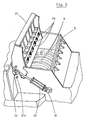
- the part of the housing located above the hammer rotor 4 2 designed as an impact chute 13 open at the top and bottom, the height of which corresponds approximately to the impact circle of the hammer rotor 4 above the center line of the rotor.
- the baffle shaft 13 is covered with a classifying grate or outlet grate 14, which is provided with grate openings 19 and extends tangentially to the direction of rotation R of the hammer rotor 4 perpendicular to the axis of the baffle shaft 13 (see FIG. 1).
- the classifying or outlet grate 14 is mounted so as to be pivotable about a pivot axis 14a.
- Two hydraulic cylinders 15 - which engage on the one hand on the lever 15a via articulated connections 16, 17 and on the other hand are fastened to the housing 2 of the hammer breaker 1 or to the hood 18 - are used to open or pivot the outlet grate 14 into the various desired positions which can be adjusted to match the required density and piece size.
- Fig. 1 two positions for the outlet grate 14 are shown, with the largest projection b resulting in the lower position A-apart from the possible adjustment of the pivoting position of the grate to achieve a specific density and piece size with the invention, one each to the Wear of the hammers adjusted grate pivot position can be selected.
- Position A would be adjusted after the hammers have worn out; in the case of sharp hammers, position B would be set with the smaller projection b s in order to achieve the required scrap density.
- positions between positions A and B are of course also possible.
- the upper housing part is designed in an arc shape in the pivoting area of the grate, so that - with the example of Fig. 1 - between positions A and B of the grate with its end face along the housing drives or has only a slight distance from the housing wall, so that a tight seal for shot parts is created.
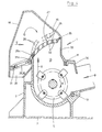
- the outlet grille 21 is, in an alternative embodiment to the outlet grille 14 which is horizontally formed and arranged in FIG. 1, preferably curved in an arc shape (arch grate) and covers the baffle shaft 13 obliquely at the top.
- the outlet grate 21 is provided with grate openings 25.
- the outlet grate 21 is pivoted about the pivot axis 21a into the respectively desired position by means of two hydraulic cylinders 22 which are fastened to the outlet grate 21 on the one hand and to the hammer breaker housing 2 on the other hand by means of articulated connections 23, 24 - similar to the outlet grate shown in FIG. 5.
- the lowest opening projection area results, as shown in FIG.
- the crushable coarse parts possibly rotating in the crusher housing 2 can be ejected through the impact shaft 13 released by the opened outlet grate 21.
- the outlet grate 26 shown in FIG. 4, which is also designed as a curved grate, is provided with grate openings 32.
- the outlet grate 26 comprises a total grate surface 27, of which a grate part 28, which can be pivoted independently, can be brought into or pivoted into the position shown in dashed lines in FIG. 4, if necessary - namely when the coarse parts have to be ejected from the crusher housing 2.
- a slightly open pivoting position of the grate 26 is also shown in dashed lines, it being clear that here the end seal to the housing takes place via a lip 35 cast onto the free end of the grate, which in turn rests against the circularly shaped housing wall in the various working positions .
- the lip 35 in particular in its form shown in FIG. 4 - bent back outwards from the inside of the shredder - creates a greater distance between these openings and the housing or hood wall above the grate openings at the end due to the associated recessing of the housing wall, ie the desired effect
- optimal use is made of the already divided grate surface.
- Both grate parts, total grate surface 27 and the independently pivotable grate part 28 are mounted so as to be pivotable about the same pivot axis 26a.
- the independently pivoting grate part 28 is via a hydraulic cylinder 29 and a hinge connection 31, which is fastened to the crusher housing 2 and a hinge connection 31a, which is fastened to the grate part 28, in the desired manner (see also FIG. 5).
- the two grate parts 27, 28 are connected to one another as a possible embodiment in the manner resulting from the following description of FIG. 5.
- other options are also available, for example by means of bolt locks, but this is not as advantageous as the version shown in FIG. 5.
- the grate part 28 (“coarse grate") and the "residual arch grate” 26 are mounted on the common pivot axis 26a.
- the arched grate is pivoted by the hydraulic cylinder 30 via a swivel lever 30a on the hub of the arched grate 26, regardless of which the opening or closing of the coarse grate can be effected via the hydraulic cylinder 29 and a swivel lever 29a on the axis 26a.
- Appropriate limit switches on the hydraulic cylinders ensure that the position of the arch grating 26 coincides with that of the coarse grating 28 in the respective pivot positions.
- This positional correspondence can also be achieved by the cross-sectional shape shown in FIG. 6 for the grate parts, namely that the coarse grate 28 tapers conically towards the shredder interior on the three sides movable relative to the outlet grate 26 is (see FIG. 6) that when the outlet grate 26 is pivoted open, the coarse grate 28 is automatically taken along. If it is then necessary in any position of the arch grate 27 to let coarse parts out of the interior, the coarse part grate 28 is opened further without difficulty by acting on the hydraulic cylinder assigned to the coarse part grate 28.
- the return to the overall closed position is also achieved hydraulically, and in individual cases the corresponding action on the hydraulic cylinder assigned to the coarse grate 28 may be sufficient, since in this direction of movement the outlet grate is "taken along" by the coarse grate in this direction of movement.
- the coarse parts are ejected through the open grate part 28, which can be pivoted via the hydraulic cylinder 29 and can be swung out of the total grate surface 27 (see dashed illustration).
- the outlet grate 21 or grate part 28 After ejecting the crushable coarse parts by opening the outlet grate 21 or grate part 28, the outlet grate 21 or grate part 28 is closed again sen and returns to the starting position shown in Fig. 2 and 4 respectively.
- the outlet grate 21 or the entire grate surface 27 is adjusted with the hydraulic cylinders 22 or 29 with a larger opening angle or pivoted into a position different from the starting position, whereby the material to be shredded due to the changed angle of impact on the grate, the required piece size is given or the desired density is achieved.
- the outlet grate 21 can be pivoted or turned on in such a way that material jamming below the grate surface meets the largest possible cross-section or the largest possible projection of the grate openings 25 and the jam can accordingly be quickly removed again.
- outlet grate is provided with sloping grate passages already in the starting position relative to the tangential discharge direction, i.e. pivoting of the grate in the embodiment according to FIG. 2 is possible, for example, to enlarge the effective passages.
Priority Applications (1)
| Application Number | Priority Date | Filing Date | Title |
|---|---|---|---|
| AT83108411T ATE28276T1 (de) | 1982-09-16 | 1983-08-26 | Hammerbrecher. |
Applications Claiming Priority (2)
| Application Number | Priority Date | Filing Date | Title |
|---|---|---|---|
| DE3234298 | 1982-09-16 | ||
| DE3234298A DE3234298C2 (de) | 1982-09-16 | 1982-09-16 | Hammerbrecher |
Publications (3)
| Publication Number | Publication Date |
|---|---|
| EP0103778A2 true EP0103778A2 (fr) | 1984-03-28 |
| EP0103778A3 EP0103778A3 (en) | 1985-11-06 |
| EP0103778B1 EP0103778B1 (fr) | 1987-07-15 |
Family
ID=6173337
Family Applications (1)
| Application Number | Title | Priority Date | Filing Date |
|---|---|---|---|
| EP83108411A Expired EP0103778B1 (fr) | 1982-09-16 | 1983-08-26 | Broyeur à marteaux |
Country Status (7)
| Country | Link |
|---|---|
| US (1) | US4798345A (fr) |
| EP (1) | EP0103778B1 (fr) |
| JP (1) | JPS5973061A (fr) |
| AT (1) | ATE28276T1 (fr) |
| AU (1) | AU559475B2 (fr) |
| DE (2) | DE3234298C2 (fr) |
| ES (1) | ES8405290A1 (fr) |
Cited By (7)
| Publication number | Priority date | Publication date | Assignee | Title |
|---|---|---|---|---|
| FR2598100A1 (fr) * | 1986-05-02 | 1987-11-06 | Copex | Dispositif d'ejection des matieres imbroyables et de variation du rendement d'un broyeur a marteaux pour le traitement des ferrailles |
| EP0254173A3 (en) * | 1986-07-23 | 1989-02-01 | Lindemann Maschinenfabrik Gmbh | Grate for crushers |
| FR2634399A1 (fr) * | 1988-07-19 | 1990-01-26 | Becker Arnaud | Broyeur a marteaux pour le dechiquetage d'objets metalliques |
| WO1990000933A1 (fr) * | 1988-07-19 | 1990-02-08 | Arnaud Becker | Broyeur a marteaux pour le dechiquetage d'objets metalliques |
| FR2638662A1 (fr) * | 1988-11-10 | 1990-05-11 | Becker Arnaud | Broyeur a marteaux, a alimentation centrale, pour le dechiquetage d'objets metalliques |
| GB2253361A (en) * | 1991-02-15 | 1992-09-09 | Ronald Frederick Bourne | Treatment of particulate material - milling, classifying |
| WO2023285302A1 (fr) * | 2021-07-13 | 2023-01-19 | TSR Recycling GmbH & Co. KG | Procédé de production de produits de ferraille à haut degré de pureté à partir d'une matière première non homogène |
Families Citing this family (18)
| Publication number | Priority date | Publication date | Assignee | Title |
|---|---|---|---|---|
| DE3431658C1 (de) * | 1984-08-29 | 1986-01-23 | Thyssen Industrie Ag, 4300 Essen | Ausbildung des Arbeitsspalts bei einer Zerkleinerungsmaschine mit waagerecht angeordnetem Hammerbrecherrotor |
| DE3517579A1 (de) * | 1985-05-15 | 1986-11-20 | Thyssen Industrie Ag, 4300 Essen | Ausbildung des gehaeusebodens von zerkleinerungsmaschinen |
| YU211189A (en) * | 1988-11-03 | 1992-05-28 | Akt Consultants | Device and a process for drying and grinding |
| DE4016295A1 (de) * | 1990-05-21 | 1991-11-28 | Lindemann Maschfab Gmbh | Hammerbrecher |
| DE19712587C2 (de) * | 1997-03-26 | 2001-11-15 | Svedala Lindemann Gmbh | Gehäuse für eine Zerkleinerungsmaschine |
| KR100916689B1 (ko) * | 2003-01-17 | 2009-09-11 | 가부시키가이샤 이구순도 재팬 | 파쇄장치 |
| JP6800589B2 (ja) * | 2016-03-02 | 2020-12-16 | 株式会社キンキ | 打撃部材を有する破砕機 |
| DE102020102607A1 (de) | 2020-02-03 | 2021-08-05 | Albert Hoffmann Gmbh | Hammermühle |
| DE102020102611B4 (de) | 2020-02-03 | 2023-04-27 | Albert Hoffmann Gmbh | Hammermühle |
| DE102020102614B4 (de) | 2020-02-03 | 2023-10-26 | Albert Hoffmann Gmbh | Hammermühle |
| DE102021006579A1 (de) | 2021-07-13 | 2023-01-19 | TSR Recycling GmbH & Co. KG | Verbessertes Verfahren zur Herstellung von Schrottprodukten |
| DE102021006582A1 (de) | 2021-07-13 | 2023-01-19 | TSR Recycling GmbH & Co. KG | Verbessertes Verfahren zur Herstellung von Schrottprodukten |
| DE102021006581A1 (de) | 2021-07-13 | 2023-01-19 | TSR Recycling GmbH & Co. KG | Verbessertes Verfahren zur Herstellung von Schrottprodukten |
| DE102021006580A1 (de) | 2021-07-13 | 2023-01-19 | TSR Recycling GmbH & Co. KG | Verbessertes Verfahren zur Herstellung von Schrottprodukten |
| DE102021006583A1 (de) | 2021-07-13 | 2023-01-19 | TSR Recycling GmbH & Co. KG | Verbessertes Verfahren zur Herstellung von Schrottprodukten |
| EP4173716A1 (fr) | 2021-10-29 | 2023-05-03 | Comes Maschinen- und Apparatebau GmbH | Machine de broyage |
| CN114082486B (zh) * | 2022-01-17 | 2022-04-01 | 河北燕山钢铁集团有限公司 | 一种废钢破碎回收再利用装置 |
| CN117309532B (zh) * | 2023-11-30 | 2024-02-02 | 彩客华煜化学有限公司 | 一种湿品dsd酸物料均匀制样装置 |
Citations (5)
| Publication number | Priority date | Publication date | Assignee | Title |
|---|---|---|---|---|
| DE648754C (de) * | 1937-08-07 | Fraenkel & Viebahn | Sieblose Schlaegermuehle | |
| DE867779C (de) * | 1951-05-11 | 1953-02-19 | Andreas Maschb Ges M B H | Schlaegermuehle mit festen oder losen Schlaegern |
| DE1272091B (de) * | 1965-03-18 | 1968-07-04 | Alton S Newell | Hammerbrecher zum Zerkleinen von Abfaellen, insbesondere von metallischen Gegenstaenden |
| FR2325431A1 (fr) * | 1975-09-29 | 1977-04-22 | Gloux Theophile | Appareil de broyage pour cereales seches ou humides ou tous autres produits d'alimentation du betail |
| US4146184A (en) * | 1976-09-20 | 1979-03-27 | Sivyer Steel Corporation | Shredder with grate door |
Family Cites Families (10)
| Publication number | Priority date | Publication date | Assignee | Title |
|---|---|---|---|---|
| US2734686A (en) * | 1956-02-14 | oberhellmann | ||
| US759856A (en) * | 1903-11-30 | 1904-05-17 | George W Borton | Pulverizer, breaker, or disintegrator. |
| US1125137A (en) * | 1907-02-12 | 1915-01-19 | Jeffrey Mfg Co | Pulverizer. |
| US2317909A (en) * | 1942-05-25 | 1943-04-27 | Gruendler Grusher & Pulverizer | Cage for grinding machines and the like |
| US3915395A (en) * | 1971-10-01 | 1975-10-28 | Pennsylvania Crusher Corp | Over and out material reducer |
| BE787109A (fr) * | 1972-08-02 | 1972-12-01 | George & Cie | Broyeur de ferrailles adapte au procede dit ''cryogenique'' |
| US4009836A (en) * | 1975-06-30 | 1977-03-01 | American Pulverizer Company | Material reducing machine |
| DE2713177C2 (de) * | 1977-03-25 | 1989-06-08 | Lindemann Maschinenfabrik GmbH, 4000 Düsseldorf | Hammerbrecher |
| JPS5820317B2 (ja) * | 1979-12-11 | 1983-04-22 | 手塚興産株式会社 | 破砕機 |
| DE3147634C2 (de) * | 1981-12-02 | 1984-12-13 | Lindemann Maschinenfabrik Gmbh, 4000 Duesseldorf | Papierzerkleinerer und Verfahren zum Betrieb |
-
1982
- 1982-09-16 DE DE3234298A patent/DE3234298C2/de not_active Expired
-
1983
- 1983-08-26 DE DE8383108411T patent/DE3372445D1/de not_active Expired
- 1983-08-26 AT AT83108411T patent/ATE28276T1/de not_active IP Right Cessation
- 1983-08-26 EP EP83108411A patent/EP0103778B1/fr not_active Expired
- 1983-09-09 AU AU18983/83A patent/AU559475B2/en not_active Ceased
- 1983-09-14 JP JP58168496A patent/JPS5973061A/ja active Granted
- 1983-09-15 ES ES525627A patent/ES8405290A1/es not_active Expired
-
1987
- 1987-09-21 US US07/099,666 patent/US4798345A/en not_active Expired - Lifetime
Patent Citations (5)
| Publication number | Priority date | Publication date | Assignee | Title |
|---|---|---|---|---|
| DE648754C (de) * | 1937-08-07 | Fraenkel & Viebahn | Sieblose Schlaegermuehle | |
| DE867779C (de) * | 1951-05-11 | 1953-02-19 | Andreas Maschb Ges M B H | Schlaegermuehle mit festen oder losen Schlaegern |
| DE1272091B (de) * | 1965-03-18 | 1968-07-04 | Alton S Newell | Hammerbrecher zum Zerkleinen von Abfaellen, insbesondere von metallischen Gegenstaenden |
| FR2325431A1 (fr) * | 1975-09-29 | 1977-04-22 | Gloux Theophile | Appareil de broyage pour cereales seches ou humides ou tous autres produits d'alimentation du betail |
| US4146184A (en) * | 1976-09-20 | 1979-03-27 | Sivyer Steel Corporation | Shredder with grate door |
Cited By (10)
| Publication number | Priority date | Publication date | Assignee | Title |
|---|---|---|---|---|
| FR2598100A1 (fr) * | 1986-05-02 | 1987-11-06 | Copex | Dispositif d'ejection des matieres imbroyables et de variation du rendement d'un broyeur a marteaux pour le traitement des ferrailles |
| EP0254173A3 (en) * | 1986-07-23 | 1989-02-01 | Lindemann Maschinenfabrik Gmbh | Grate for crushers |
| US4982904A (en) * | 1986-07-23 | 1991-01-08 | Lindemann Maschinenfabrik G.M.B.H. | Screen for comminuting machines |
| FR2634399A1 (fr) * | 1988-07-19 | 1990-01-26 | Becker Arnaud | Broyeur a marteaux pour le dechiquetage d'objets metalliques |
| WO1990000933A1 (fr) * | 1988-07-19 | 1990-02-08 | Arnaud Becker | Broyeur a marteaux pour le dechiquetage d'objets metalliques |
| FR2638662A1 (fr) * | 1988-11-10 | 1990-05-11 | Becker Arnaud | Broyeur a marteaux, a alimentation centrale, pour le dechiquetage d'objets metalliques |
| EP0370861A1 (fr) * | 1988-11-10 | 1990-05-30 | Arnaud Becker | Broyeur à marteaux, à alimentation centrale, pour le déchiquetage d'objets métalliques |
| GB2253361A (en) * | 1991-02-15 | 1992-09-09 | Ronald Frederick Bourne | Treatment of particulate material - milling, classifying |
| GB2253361B (en) * | 1991-02-15 | 1995-01-04 | Ronald Frederick Bourne | Treatment of particulate material by use of a mill, classifier or grinder unit |
| WO2023285302A1 (fr) * | 2021-07-13 | 2023-01-19 | TSR Recycling GmbH & Co. KG | Procédé de production de produits de ferraille à haut degré de pureté à partir d'une matière première non homogène |
Also Published As
| Publication number | Publication date |
|---|---|
| DE3234298A1 (de) | 1984-03-22 |
| ATE28276T1 (de) | 1987-08-15 |
| DE3234298C2 (de) | 1985-12-19 |
| EP0103778B1 (fr) | 1987-07-15 |
| ES525627A0 (es) | 1984-06-01 |
| AU559475B2 (en) | 1987-03-12 |
| US4798345A (en) | 1989-01-17 |
| EP0103778A3 (en) | 1985-11-06 |
| JPS5973061A (ja) | 1984-04-25 |
| AU1898383A (en) | 1984-03-22 |
| DE3372445D1 (en) | 1987-08-20 |
| ES8405290A1 (es) | 1984-06-01 |
| JPH0344816B2 (fr) | 1991-07-09 |
Similar Documents
| Publication | Publication Date | Title |
|---|---|---|
| EP0103778B1 (fr) | Broyeur à marteaux | |
| DE3147634C2 (de) | Papierzerkleinerer und Verfahren zum Betrieb | |
| EP1536892B1 (fr) | Dispositif de broyage | |
| EP0254173B1 (fr) | Grille pour broyeurs | |
| EP0376011B1 (fr) | Enveloppe pour concasseur de ferrailles | |
| DE4016295C2 (fr) | ||
| DE2516014C3 (de) | Zerkleinerungsmaschine für Abfälle | |
| CH629975A5 (de) | Hammerbrecher. | |
| DE10006757C1 (de) | Verfahren und Vorrichtungen zum Zerkleinern von Spänen | |
| DE3821360A1 (de) | Prallzerkleinerer | |
| DE4328506C1 (de) | Spänebrecher | |
| AT398712B (de) | Restholzzerkleinerungsmaschine | |
| DE2448092A1 (de) | Zerkleinerer zum aufbereiten von duennwandigem schrott | |
| EP0486872B1 (fr) | Déchiqueteur rotatif pour le broyage de déchets | |
| EP0380811B1 (fr) | Broyeur à impact | |
| WO2018050809A1 (fr) | Rotor de hachage pour un dispositif de broyage, en particulier hachoir | |
| EP3766583B1 (fr) | Dispositif de désintégration | |
| EP0190417B1 (fr) | Equipement adapté à la désagrégation de papier de rebut | |
| DE102021126898B3 (de) | Zerkleinerer zum Zerkleinern von Spänen | |
| DE19530428C1 (de) | Granulatmühle | |
| EP1625889B1 (fr) | Dispositif et procédé de fragmentation et dont utilisation | |
| DE19614030A1 (de) | Zerkleinerungsmaschine | |
| DE102022128788A1 (de) | Zerkleinerungsmaschine | |
| DE4328687A1 (de) | Nach dem Rotationsscheren-Prinzip arbeitender Shredder | |
| DE3839341A1 (de) | Verfahren und einrichtung zum universellen zerkleinern und trennen von materialien |
Legal Events
| Date | Code | Title | Description |
|---|---|---|---|
| PUAI | Public reference made under article 153(3) epc to a published international application that has entered the european phase |
Free format text: ORIGINAL CODE: 0009012 |
|
| AK | Designated contracting states |
Designated state(s): AT BE CH DE FR GB IT LI NL SE |
|
| PUAL | Search report despatched |
Free format text: ORIGINAL CODE: 0009013 |
|
| AK | Designated contracting states |
Designated state(s): AT BE CH DE FR GB IT LI NL SE |
|
| 17P | Request for examination filed |
Effective date: 19851210 |
|
| 17Q | First examination report despatched |
Effective date: 19860625 |
|
| ITF | It: translation for a ep patent filed |
Owner name: BARZANO' E ZANARDO ROMA S.P.A. |
|
| GRAA | (expected) grant |
Free format text: ORIGINAL CODE: 0009210 |
|
| AK | Designated contracting states |
Kind code of ref document: B1 Designated state(s): AT BE CH DE FR GB IT LI NL SE |
|
| REF | Corresponds to: |
Ref document number: 28276 Country of ref document: AT Date of ref document: 19870815 Kind code of ref document: T |
|
| REF | Corresponds to: |
Ref document number: 3372445 Country of ref document: DE Date of ref document: 19870820 |
|
| ET | Fr: translation filed | ||
| PLBE | No opposition filed within time limit |
Free format text: ORIGINAL CODE: 0009261 |
|
| STAA | Information on the status of an ep patent application or granted ep patent |
Free format text: STATUS: NO OPPOSITION FILED WITHIN TIME LIMIT |
|
| 26N | No opposition filed | ||
| ITTA | It: last paid annual fee | ||
| PGFP | Annual fee paid to national office [announced via postgrant information from national office to epo] |
Ref country code: SE Payment date: 19940824 Year of fee payment: 12 |
|
| EAL | Se: european patent in force in sweden |
Ref document number: 83108411.6 |
|
| PG25 | Lapsed in a contracting state [announced via postgrant information from national office to epo] |
Ref country code: SE Effective date: 19950827 |
|
| EUG | Se: european patent has lapsed |
Ref document number: 83108411.6 |
|
| REG | Reference to a national code |
Ref country code: GB Ref legal event code: IF02 |
|
| PGFP | Annual fee paid to national office [announced via postgrant information from national office to epo] |
Ref country code: CH Payment date: 20020717 Year of fee payment: 20 |
|
| PGFP | Annual fee paid to national office [announced via postgrant information from national office to epo] |
Ref country code: NL Payment date: 20020725 Year of fee payment: 20 Ref country code: BE Payment date: 20020725 Year of fee payment: 20 |
|
| PGFP | Annual fee paid to national office [announced via postgrant information from national office to epo] |
Ref country code: AT Payment date: 20020729 Year of fee payment: 20 |
|
| PGFP | Annual fee paid to national office [announced via postgrant information from national office to epo] |
Ref country code: GB Payment date: 20020730 Year of fee payment: 20 |
|
| PGFP | Annual fee paid to national office [announced via postgrant information from national office to epo] |
Ref country code: DE Payment date: 20020809 Year of fee payment: 20 |
|
| PGFP | Annual fee paid to national office [announced via postgrant information from national office to epo] |
Ref country code: FR Payment date: 20020812 Year of fee payment: 20 |
|
| BECN | Be: change of holder's name |
Owner name: *METSO LINDEMANN G.M.B.H. Effective date: 20021220 |
|
| PG25 | Lapsed in a contracting state [announced via postgrant information from national office to epo] |
Ref country code: LI Free format text: LAPSE BECAUSE OF EXPIRATION OF PROTECTION Effective date: 20030825 Ref country code: GB Free format text: LAPSE BECAUSE OF EXPIRATION OF PROTECTION Effective date: 20030825 Ref country code: CH Free format text: LAPSE BECAUSE OF EXPIRATION OF PROTECTION Effective date: 20030825 |
|
| PG25 | Lapsed in a contracting state [announced via postgrant information from national office to epo] |
Ref country code: NL Free format text: LAPSE BECAUSE OF EXPIRATION OF PROTECTION Effective date: 20030826 Ref country code: AT Free format text: LAPSE BECAUSE OF EXPIRATION OF PROTECTION Effective date: 20030826 |
|
| REG | Reference to a national code |
Ref country code: GB Ref legal event code: PE20 |
|
| REG | Reference to a national code |
Ref country code: CH Ref legal event code: PL |
|
| NLV7 | Nl: ceased due to reaching the maximum lifetime of a patent |
Effective date: 20030826 |