EP0103440A1 - Verfahren und Vorrichtung zum Herstellen von Bechern mit einem Rand - Google Patents
Verfahren und Vorrichtung zum Herstellen von Bechern mit einem Rand Download PDFInfo
- Publication number
- EP0103440A1 EP0103440A1 EP83305026A EP83305026A EP0103440A1 EP 0103440 A1 EP0103440 A1 EP 0103440A1 EP 83305026 A EP83305026 A EP 83305026A EP 83305026 A EP83305026 A EP 83305026A EP 0103440 A1 EP0103440 A1 EP 0103440A1
- Authority
- EP
- European Patent Office
- Prior art keywords
- cup
- bending
- lip
- rim
- side wall
- Prior art date
- Legal status (The legal status is an assumption and is not a legal conclusion. Google has not performed a legal analysis and makes no representation as to the accuracy of the status listed.)
- Granted
Links
Images


Classifications
-
- B—PERFORMING OPERATIONS; TRANSPORTING
- B29—WORKING OF PLASTICS; WORKING OF SUBSTANCES IN A PLASTIC STATE IN GENERAL
- B29C—SHAPING OR JOINING OF PLASTICS; SHAPING OF MATERIAL IN A PLASTIC STATE, NOT OTHERWISE PROVIDED FOR; AFTER-TREATMENT OF THE SHAPED PRODUCTS, e.g. REPAIRING
- B29C57/00—Shaping of tube ends, e.g. flanging, belling or closing; Apparatus therefor, e.g. collapsible mandrels
- B29C57/12—Rim rolling
-
- B—PERFORMING OPERATIONS; TRANSPORTING
- B29—WORKING OF PLASTICS; WORKING OF SUBSTANCES IN A PLASTIC STATE IN GENERAL
- B29C—SHAPING OR JOINING OF PLASTICS; SHAPING OF MATERIAL IN A PLASTIC STATE, NOT OTHERWISE PROVIDED FOR; AFTER-TREATMENT OF THE SHAPED PRODUCTS, e.g. REPAIRING
- B29C53/00—Shaping by bending, folding, twisting, straightening or flattening; Apparatus therefor
- B29C53/02—Bending or folding
- B29C53/04—Bending or folding of plates or sheets
- B29C53/06—Forming folding lines by pressing or scoring
-
- B—PERFORMING OPERATIONS; TRANSPORTING
- B29—WORKING OF PLASTICS; WORKING OF SUBSTANCES IN A PLASTIC STATE IN GENERAL
- B29C—SHAPING OR JOINING OF PLASTICS; SHAPING OF MATERIAL IN A PLASTIC STATE, NOT OTHERWISE PROVIDED FOR; AFTER-TREATMENT OF THE SHAPED PRODUCTS, e.g. REPAIRING
- B29C53/00—Shaping by bending, folding, twisting, straightening or flattening; Apparatus therefor
- B29C53/80—Component parts, details or accessories; Auxiliary operations
- B29C53/84—Heating or cooling
-
- B—PERFORMING OPERATIONS; TRANSPORTING
- B29—WORKING OF PLASTICS; WORKING OF SUBSTANCES IN A PLASTIC STATE IN GENERAL
- B29C—SHAPING OR JOINING OF PLASTICS; SHAPING OF MATERIAL IN A PLASTIC STATE, NOT OTHERWISE PROVIDED FOR; AFTER-TREATMENT OF THE SHAPED PRODUCTS, e.g. REPAIRING
- B29C37/00—Component parts, details, accessories or auxiliary operations, not covered by group B29C33/00 or B29C35/00
- B29C37/0053—Moulding articles characterised by the shape of the surface, e.g. ribs, high polish
- B29C37/0057—Moulding single grooves or ribs, e.g. tear lines
-
- B—PERFORMING OPERATIONS; TRANSPORTING
- B29—WORKING OF PLASTICS; WORKING OF SUBSTANCES IN A PLASTIC STATE IN GENERAL
- B29K—INDEXING SCHEME ASSOCIATED WITH SUBCLASSES B29B, B29C OR B29D, RELATING TO MOULDING MATERIALS OR TO MATERIALS FOR MOULDS, REINFORCEMENTS, FILLERS OR PREFORMED PARTS, e.g. INSERTS
- B29K2023/00—Use of polyalkenes or derivatives thereof as moulding material
- B29K2023/04—Polymers of ethylene
- B29K2023/06—PE, i.e. polyethylene
-
- B—PERFORMING OPERATIONS; TRANSPORTING
- B29—WORKING OF PLASTICS; WORKING OF SUBSTANCES IN A PLASTIC STATE IN GENERAL
- B29K—INDEXING SCHEME ASSOCIATED WITH SUBCLASSES B29B, B29C OR B29D, RELATING TO MOULDING MATERIALS OR TO MATERIALS FOR MOULDS, REINFORCEMENTS, FILLERS OR PREFORMED PARTS, e.g. INSERTS
- B29K2023/00—Use of polyalkenes or derivatives thereof as moulding material
- B29K2023/10—Polymers of propylene
- B29K2023/12—PP, i.e. polypropylene
-
- B—PERFORMING OPERATIONS; TRANSPORTING
- B29—WORKING OF PLASTICS; WORKING OF SUBSTANCES IN A PLASTIC STATE IN GENERAL
- B29K—INDEXING SCHEME ASSOCIATED WITH SUBCLASSES B29B, B29C OR B29D, RELATING TO MOULDING MATERIALS OR TO MATERIALS FOR MOULDS, REINFORCEMENTS, FILLERS OR PREFORMED PARTS, e.g. INSERTS
- B29K2025/00—Use of polymers of vinyl-aromatic compounds or derivatives thereof as moulding material
-
- B—PERFORMING OPERATIONS; TRANSPORTING
- B29—WORKING OF PLASTICS; WORKING OF SUBSTANCES IN A PLASTIC STATE IN GENERAL
- B29K—INDEXING SCHEME ASSOCIATED WITH SUBCLASSES B29B, B29C OR B29D, RELATING TO MOULDING MATERIALS OR TO MATERIALS FOR MOULDS, REINFORCEMENTS, FILLERS OR PREFORMED PARTS, e.g. INSERTS
- B29K2101/00—Use of unspecified macromolecular compounds as moulding material
- B29K2101/12—Thermoplastic materials
-
- B—PERFORMING OPERATIONS; TRANSPORTING
- B29—WORKING OF PLASTICS; WORKING OF SUBSTANCES IN A PLASTIC STATE IN GENERAL
- B29K—INDEXING SCHEME ASSOCIATED WITH SUBCLASSES B29B, B29C OR B29D, RELATING TO MOULDING MATERIALS OR TO MATERIALS FOR MOULDS, REINFORCEMENTS, FILLERS OR PREFORMED PARTS, e.g. INSERTS
- B29K2105/00—Condition, form or state of moulded material or of the material to be shaped
- B29K2105/04—Condition, form or state of moulded material or of the material to be shaped cellular or porous
-
- B—PERFORMING OPERATIONS; TRANSPORTING
- B29—WORKING OF PLASTICS; WORKING OF SUBSTANCES IN A PLASTIC STATE IN GENERAL
- B29L—INDEXING SCHEME ASSOCIATED WITH SUBCLASS B29C, RELATING TO PARTICULAR ARTICLES
- B29L2031/00—Other particular articles
- B29L2031/712—Containers; Packaging elements or accessories, Packages
- B29L2031/7132—Bowls, Cups, Glasses
-
- Y—GENERAL TAGGING OF NEW TECHNOLOGICAL DEVELOPMENTS; GENERAL TAGGING OF CROSS-SECTIONAL TECHNOLOGIES SPANNING OVER SEVERAL SECTIONS OF THE IPC; TECHNICAL SUBJECTS COVERED BY FORMER USPC CROSS-REFERENCE ART COLLECTIONS [XRACs] AND DIGESTS
- Y10—TECHNICAL SUBJECTS COVERED BY FORMER USPC
- Y10S—TECHNICAL SUBJECTS COVERED BY FORMER USPC CROSS-REFERENCE ART COLLECTIONS [XRACs] AND DIGESTS
- Y10S264/00—Plastic and nonmetallic article shaping or treating: processes
- Y10S264/04—Molding and forming bendable and flexible product from rigid preform
Definitions
- the present invention relates to a method and apparatus for manufacturing cups having a lip. More specifically, the invention relates to a method for forming a lip on a cup formed in one piece by vacuum or press moulding from a thermoplastic resin foamed sheet material, such as polystyrene foamed sheet, the lip being such that it extends radially outwardly from the mouth of the cup and is bent at the end thereof radially inwardly towards the side wall of the cup, and an apparatus for forming such lip.
- a thermoplastic resin foamed sheet material such as polystyrene foamed sheet
- Thermoplastic resin foamed sheet materials have good heat-insulating properties, permit easy moulding, and are highly workable into complex curved surface configurations. With such advantages, they have recently been widely used for manufacture into food and beverage containers. Indeed, cups made of such material are largely supplanting paper cups.
- cups of such resin foamed material are manufactured in such a way that a piece of thermoplastic resin foamed sheet is formed into a number of cup blanks arranged in line. The individual cup blanks so formed are trimmed on the outer peripheries thereof.
- each resulting cup is such that it has at its mouth portion a horizontally outwardly extending rim or such a rim having a downwardly extending portion.
- the end of the trimmed rim portion is exposed outwardly of the top of the side wall. This gives the cup an unaesthetic appearance. Moreover, the outwardly extending end of the rim is easily liable to become soiled, which is undesirable from the sanitary point of view. A further disadvantage is that the cup may be easily cracked or torn at its peripheral edge. Another difficulty is that such projection feels unpleasant to the mouth.
- Japanese Patent Publication No. 38-24594 discloses a lip forming method such that the side wall of a container is heated and simultaneously pressed under rotation against a mould, whereby a lip is formed on the container.
- This method can be applied to containers formed of non-foamed thermoplastic resin sheet materials.
- a container formed of a thermoplastic resin foamed sheet material there are problems to be solved.
- One difficulty is that the material has insignificant elongation, which means poor workability for lip formation. As such, the finished product may have an uneven surface or creases, or less dimensional accuracy.
- Another difficulty is that because of its high heat-insulation performance such foamed sheet material can hardly be heated in a short time to such a temperature as will permit lip formation. Therefore, said method cannot be applied as it is to cups formed of foamed sheet materials.
- U.S. Pat. No. 3,933,298 discloses a method such that the outer surface of a composite container body wall layer is scored by a scoring tool to define a continuous circumferential scoreline, the body wall layer being bent at the scoreline. If the container is formed of a foamed sheet material, simple scoring by a scoring tool may not achieve sufficient bending because the restoring force of the foamed sheet material will tend to restore the scored portion to its prior condition.
- the present invention has as its primary object the provision of a method which permits efficient formation of an accurately shaped, dimensionally substantially accurate, and well finished lip on a one-piece cup formed of a thermoplastic resin foamed sheet material, and of an apparatus for practicing the method.
- the method comprises the steps of:
- a bending furrow is formed on the outer periphery of the side wall, and the rim is bent at the bending furrow down toward the side wall. Therefore, bending can be very smoothly performed along the bending furrow, a location where a most larger deformation is involved during the lip forming operation and which makes a base point for bending operation, lip formation being thus very much facilitated.
- the method according to the invention permits efficient production of cups formed of a resin foamed sheet material having a lip, the manufacture of which has been considered extremely difficult in the art, with assured neatness of finish.
- the bending furrow in the invention can comprise a linear notch or a bending groove having a certain width and that it may be formed by means of either a cutting edged blade or a hot blade, and that the bending line in the invention is the circumferential portion about the cup where bending is to take place.
- the apparatus in accordance with the present invention permits efficient practising of the method of the invention and is defined as follows:
- a bending furrow is formed by a bending line forming means while the cup holding means and the cup, as held thereby, are rotated. This permits easy-and accurate formation of a bending furrow, the subsequent bending operation being thus well facilitated.
- the cup held by the cup holding means is caused to slide axially while being kept in rotation, and the rim of the cup is bent by being pressed against the lip forming groove so that a lip is formed.
- the pressing force is evenly applied to the entire circumference of the cup and, accordingly the configuration of the lip being formed can be-well stabilized with good working efficiency being assured.
- the lip forming groove is provided with heating means permits heating the side wall to a temperature suitable for bending operation, whereby the bending operation may be performed at ease.
- the apparatus of the invention includes cup supply means and cup removal means, the entire lip forming process may be automated or continuously operated.
- the apparatus of the invention facilitates manufacture of cups on a mass or continuous production basis.
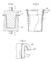
- a cup blank 1 used for the purpose of the invention is formed from a thermoplastic resin foamed sheet material S, e.g. polystyrene foamed sheet, by heating the foamed sheet material S to a moulding temperature above its softening point and subjecting same to deformation along a moulding tool consisting of a pair of dies M, M', male and female, as illustrated in Fig.
- a thermoplastic resin foamed sheet material S e.g. polystyrene foamed sheet
- the resulting cup blank has a side wall and a bottom integrally formed therewith.
- a polystyrene foamed sheet material having a density of 0.08-0.7 g/cm 3 may be used advantageously.
- Polystyrene suitable for such foamed sheet material include styrene polymers produced by polymerization of vinyl aromatic monomers such as styrene, vinyltoluene, isopropyl styrene, a-methylstyrene, nuclearomethylstyrene, chlorostyrene, or tribasic butyl styrene, or styrene copolymers produced by copolymerization of styrene monomer and 1.3-butadiene, alkyl acrylate such as butyl acrylate, ethyl acrylate, or 2-ethylhexyl acrylate, alkyl methacrylate such as methyl methacrylate, butyl methacrylate, or 2-ethylhexyl
- thermoplastic foamed resins such as polyethylene and polypropylene may be used.
- sheets of foamed resins produced by graft polymerization of styrene monomers with olefin resin, such as polyethylene or polypropylene, which constitutes a nucleus are also available for use.
- the foamed resin sheets may be of a single layer, or may be such that a non-foamed film of a resin such as high-impact polystyrene, polypropylene, polyethylene or the like is laminated in one or more layers on one or both sides of any such foamed sheet.
- a resin such as high-impact polystyrene, polypropylene, polyethylene or the like
- the thickness of the foamed sheet may be within the range of 0.5 - 3.0 mm (average product thickness).
- Non-foamed film used for lamination may be 5 - 120 microns thick (product thickness).
- the moulding temperature for the foamed sheet material may vary depending upon the material and configuration of the cup blank 1 being moulded. If foamed polystyrene sheet material is used, moulding should be carried out at 120°+ 5°C.
- Vacuum forming, press moulding, or any other conventional sheet moulding method may be employed at choice.
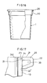
- the cup blank 1 as formed is of substantially cylindrical shape with its side wall being upwardly flared having the upper portion 10 thereof is substantially vertically straight. There is a step formed between the upper portion 10 and the upwardly flared lower portion of the side wall so that a plurality of cups 1 may be easily stacked one over the other or removed one after another from such a stack.
- the overall configuration of the cup is not limited to such elongate shape suitable for beverage service as shown.
- the cup may be of laterally broader shape like a bowl or otherwise.
- the cup 1 At the top of the opening defined by the side wall, the cup 1 has a radially outwardly extending hook-shaped rim 20', the end 22' of the rim 20' being circumferentially trimmed in such a manner that if faces obliquely downward.
- the configuration of the rim 20' is not limited to the one as shown, but it may be varied freely inasmuch as it is bent or curved in a hook-shaped pattern. For example, it may be substantially U-shaped, or of angular or arcuate shape. It is to be noted that the rim 20' should be so formed that its end 22' faces obliquely downward or substantially downward.
- the rim 20' of the above-described cup blank 1 is further bent to form a lip such that the end 22' of the rim 20 is bent toward the side wall.
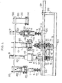
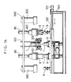
- the apparatus of the invention which is designed for forming such a lip on the cup blank is schematically shown in Fig. 4.
- the apparatus shown is adapted to form lips on a plurality of cup blanks 1 one at a time.
- a spiral feeder 100 for feeding cup blanks 1.
- Cavity blocks 8, 8 which act as cup removal means are disposed respectively at the lefthand sides of the spiral feeder 100, and air chuters 300, 300 for collecting cups 1 are disposed, one at lefthand side and the other at righthand side, outwardly of the cavity blocks.
- the spiral feeder 100, the two cavity blocks 8, 8 and the two air chuters 300, 300 are taken as one unit. A plurality of such units may be arranged together. In that case, an air chuter 300 interposed between each two adjacent units may be commonly used for the adjacent units.
- the individual spiral feeders 100, cavity blocks 8, and air chuters 300 are supported by a stationary beam 500 located above the apparatus, to which beam they are fixed.
- the cavity blocks 8 are upwardly and downwardly movably fixed under the stationary beam 500 through cylinder mechanisms 80.
- a moving table 520 which is horizontally movable on a stationary table 510 along the row of said components.
- the moving table 520 actuated by a cylinder mechanism 521, is adapted to reciprocate over a distance corresponding to that between each adjacent spiral feeder 100 and cavity block 8.
- the lip forming tool 6 and mandrel block 7 are moved from a position under the spiral feeder 100 to a position under the cavity block 8, and the product receiving block 9 is moved from the position under the cavity block 8 to a position under the air chuter 300.
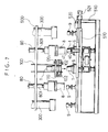
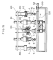
- Fig. 5 which shows the arrangement of the apparatus in front elevation, one mandrel block 7 and one lip forming tool 6 are disposed (both referring to the righthand-side one in the figure) under the spiral feeder 100.
- the spiral feeder 100 has at the centre thereof a guide portion 101 for stacking a plurality of cup blanks 1, with a pair of screws 102 disposed at both sides of the guide portion 101, so that cups 1 are dropped one by one from the guide portion 101 as the screws 102 rotate.
- a blow-off nozzle 110 is adapted to blow pressure air downwardly of the centre of the guide portion 101 to downwardly urge cups 1 falling from the guide portion 101 so that accurate and quick drop of each of the cups 1 is assured.
- a lubricant spray nozzle 120 is adapted to apply a lubricant such as silicone solution to the rim 20' of each cup blank 1.
- the lubricant serves to reduce friction between the rim 20' and the forming groove 60 of the lip forming tool 6 in the bending stage to be described hereinafter, thereby imparting better slide effect to the rim 20'. Since ther rim 20' is pressed against the forming groove 60 while being rotated, absence of lubricant may lead to development of creases on the rim 20' or torsion of the rim 20' in the direction of roation thereof under the force of friction caused between the rim 20' and the forming groove 60.
- lubricant between the rim 20' and the forming groove 60 will reduce friction and smoothen slide movement, thus eliminating the problem of crease occurrence or the like. In order to ensure smooth bending operation and satisfactory lip finish, therefore, lubricant application is necessary. Such lubricant also serves to ensure effective transfer of heat from the forming groove 60 to the rim 20' in the stage of heating.
- lubricant such as surface active agents and paraffin, as well as silicone solution.
- nozzle spraying or coating may be used. It is also possible to pour the lubricant into the clearance between the rim 20' and the forming groove 60 through a lubricant feed hole which may be provided in the inner surface of the forming groove 60.
- a conventional conveyor mechanism may be employed as means for feeding cups 1, provided that it can be adapted to drop down the cups 1, one by one.
- the moving table 520 is provided with rail grooves 522 which are in engagement with two rails 511 laid on the stationary table 510, being adapted to slide horizontally through the engagement of the rail grooves 522.
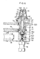
- the lip forming tool 6 is mounted on a heating table 62 fixedly placed on the moving table 520 through a cylindrical body 61 and which is adapted to perform heating through electric heater means.
- a forming groove 60 is provided on the tool 6 formed in a circular pattern which is adapted to receive the rim 20' of the cup blank 1 so that the rim 20' is bent by being pressed along the forming groove 60.
- the forming groove 60 has a sectional configuration compatible with the configuration of the rim 20' and that of a lip to be formed.
- the forming groove 60 has a rectangular section in which the inner periphery and bottom of the groove 60 are substantially at right angles relative to each other.
- the lip forming tool 6 is constructed so that its surface on the inward side of the forming groove 60 is at a slightly higher level relative to its surface on the outward side of the groove 60.
- the heating temperature of the forming tool 6 through the heating table 62 should be set at approximately 104 + 5°C adjacent the forming groove 60. This temperature is to be taken as a temperature which permits bending of the rim 20' of the cup blank 1. More specifically, the temperature is such that the upper portion of the side wall of the cup blank 1, including the rim 20', and be heated to a temperature range of above the heat deformation temperature and right below the moulding temperature of the cup blank 1.
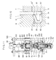
- the mandrel block 7 has a substantially truncated cone-shaped head portion 70 which is adapted to abut the interior of the cup 1 at the bottom and adjacent portion thereof, and a disc-shaped base portion 71 which is adapted to abut the interior of the cup 1 at the upper end portion thereof adjacent the rim 20'.
- the head portion 70 and base portion 71 are integrally connected to each other by a centre shaft portion 72. That is, the mandrel block 7 is adapted to engage the cup 1 by abutting the interior thereof at two portions, i.e. the bottom and the upper end adjacent the rim 20'. Such partial abutment is sufficient to support the cup 1 and protect the rim 20' against deformation during bending operation.
- a modified type of mandrel block 7 may be made such that its entire outer periphery is adapted to engage the inner surface of the cup 1.
- the head portion 70 of the mandrel block 7 has, at the centre of its top and at a plurality of locations on its side wall periphery, vacuum adsorption holes 73 communicating with a vacuum passage 730 provided inside the mandrel block 7, so that the cup 1 brought in engagement with the mandrel block 7 is held and secured through adsorption.
- vacuum adsorption holes 73 The arrangement of vacuum adsorption holes 73 is not limited to the one shown and variations may be made without departing from the scope of the invention.
- the vacuum sdsorption holes 73 may be provided only on the side wall or top of the mandrel block 7, if they can hold and secure the cup 1 by adsorption.
- vacuum pressure in the vacuum adsorption holes is set at approximately 76 - 60 mmHg.
- a mandrel shaft 74 By bolts 740.
- the mandrel shaft 74 extends through both the forming tool 6 and the heating table 62 and further into a box-shaped mounting frame 522 fixed to the underside of the moving table 520.
- the shaft 74 is rotatably supported, through bearings 750, in a bearing block 75 provided in the mounting frame 522.
- a through-hole 741 extends centrally through the mandrel shaft 74, communicating at the upper end thereof with the vacuum passage 730 inside the mandrel block 7 and at the lower end thereof with a vacuum pipe connection 752 provided on the outer periphery of the bearing block 75, via a vacuum passage 751 in the bearing block 75.
- a vacuum pipe suitably connected to a vacuum source is connected to the vacuum pipe connection 752, so that the mandrel block 7 is enabled to perform its vacuum adsorption function.
- a rod 760 of the cushioning cylinder 76 is connected to the bottom of the bearing block 75.
- the air cushioning cylinder 76 has its body portion fixed to the underside of the mounting frame 522, so that the bearing block 75, mandrel shaft 74, and mandrel block 7, all disposed above the cylinder 76, are integrally connected as one up-and-down movable assembly.
- a gear 77 is securely fitted for rotating the mandrel block.
- the gear 77 is in engagement with a drive gear 79 for a rotary actuator 78 mounted in the mounting frame 522.
- the rotary actuator 78 actuates the drive gear 79 to rotate through introduction of pressure air.
- the drive gear 79 turns through a rotation angle of aoubt 120° to rotate the mating gear 77, and accordingly the mandrel block 7 connected thereto, more than one turn.
- the number of turns or angle of rotation of the mandrel b'lock 7 is variable depending upon the angle of rotation of the drive gear 79.
- one rotary actuator 78 is disposed between two sets, right and left, of mandrels 7 and lip moulding tools 6 so that the drive gear 79 mounted on the rotary actuator 78 is in engagement with two mandrel-rotating gears 77, 77, right and left, for simultaneous rotation thereof (see Fig.6).
- the drive gear 79 and the gear 77 are designed so that the latter is in mesh with the former for rotation whether it is at an elevated position or at a lowered position as a result of its vertical movement along with the up and down movement of the mandrel shaft 74.
- the forming groove 60 is heated by the heating table 62, and accordingly the rim 20' and adjacent portion of the cup 1 is heated by way of preheating for facilitating the stage of lip formation which will be described hereinafter.
- the moving table 520 is moved to the right as seen in the figure, and the mandrel block 7 in engagement with the cup 1 and the lip forming tool 6 are positioned under the cavity block 8 on the right. Whilst, the mandrel block 7 and lip forming tool 6 on the left side are positioned under the spiral feeder 100 so that supply of cups from the spiral feeder 100 to the mandrel block 7 is initiated. It is noted that in the subsequent stages as well, operation of the left-side part of the unit apparatus will progress with some time lag behind that of the right-side counterpart.
- an upwardly extending hot-blade mounting base 40 is disposed on the stationary table 510, outwardly of the moving table 520.
- An air cylinder 41 is mounted adjacent the upper end of the mounting base 40.
- a hot blade 4 which serves as bending-line forming means, the front end 43 of the hot blade 4 being horizontally movable for access toward the mandrel block 6.
- the hot blade 4 has a sheathed heater 42 embedded therein for heating up the hot blade 4.
- the front end 43 of the hot blade 4 is shaped in rectangular or other pattern as required according to the sectional configuration of the bending groove (to be further described hereinafter) along the bending line.
- the hot blade 4 is moved toward the mandrel block 7 by driving the air cylinder 41 while the mandrel block 6 is rotated under the drive force of the rotary actuator 78.
- the front end 43 of the hot blade 4 is pressed against the outer periphery of the side wall of cup 1 at a level above the rim 20' as seen.
- the blade front end 43 is then brought in abutment with the side wall over the entire outer periphery thereof since the mandrel block 7 is rotating, a bending groove 50 being thus formed on the entire periphery at said level of the cup I.
- Fig. 9 showing an enlarged view
- the front end 43 of the hot blade which is of rectangular shape, is pressed against the outer peripheral surface of side wall of the cup 1 at a level slightly above the end 22' of curved portion of the rim 20' to melt-form a bending groove 50.
- the front end 43 of the hot blade 4 is rectangle-shaped with the following dimensions: 1.3 mm thick, 4 mm deep, and 40 mm wide.
- the heating temperature of the hot blade 4 is preferably at or above the melting temperature of the foamed sheet material of which the cup 1 is formed, e.g. 280°C. However, a temperature range of 250°C to 280°C may be conveniently employed. If so desired, temperatures of 250°C to 300°C may be applied as well.
- Groove width W should be the same or slightly larger than mean depth D of the groove. More specifically, the groove width W is preferably 0.1 - 0.3 mm larger than the groove depth D.
- the thickness T of the bottom wall 51 of the bending groove 50 it is desirable to preset the thickness T of the bottom wall 51 of the bending groove 50 to the extent that the bottom wall is thick enough to prevent the upper side wall portion 10 from breaking during the step of bending (which is to be further described hereinafter).
- the sheet material of which the cup 1 is formed comprises a foamed sheet and a non-foamed sheet laminated thereon, no part of the foamed material portion may be reserved for bottom wall 51.
- cup side-wall thickness T 1 0.5 to 3.0 mm
- groove width W T 1 + (0.1 to 0.3 mm)
- groove bottom thickness T 2 T - (0.2 to 1.0 mm).
- the bottom 51 may be sloped so that the depth of the bending groove 50 is less deep on the upper side of the cup than on the lower side.
- the configurations of the bending groove 50 can be determined by setting the configuration of front end of the hot blade 4 as required. In practice, however, bending groove 50 is fromed through hot melting, and therefore, a groove confirguration which is in complete agreement with the configuration of the hot blade front end 43.cannot be formed. Some difference between the two is tolerable if the above conditions as to the relationship between groove width W and groove depth D are satisfied.
- the configuration of the hot blade front end 43 may be formed by taking into consideration such tolerable errors.
- the bending furrow should be formed so that it is more easily bendable than any other part of the side wall 10 and can be accurately bent and deformed during the stage of pressing (which is to be described hereinafter).
- the cavity block 8 has a recess 81 adapted to fit over the cup 1 along the outer peripheral configuration thereof.
- a rotating shaft 82 which is rotatably suspended from a vertically movable member 83 through a bearing 820.
- the vertically movable member 83 is connected at its upper end to one end of a rod 801 of a cylinder mechanism 80 so that the member 83 and the cavity block 8 are moved up and down along with the movement of the cylinder mechanism 80.
- the vertically movable member 83 has guide holes 830 bored therethrough.
- each of the guide holes 830 there slidably extends a guide support 530 which hangs from an overhead beam 500 extending down to a stationary table 510, so that the horizontally movable member 83 and cavity block 8 can be moved up and down properly without run-out to right or left.
- a vacuum adsorption hole 84 which communicates with a vacuum passage 831 leads to the outer periphery of the vertically movable member 83 through the interior thereof.
- a vacuum pipe connection 832 is provided to which a vacuum pipe is connected as required which communicates with a vacuum source.
- the cylinder mechanism 80 is actuated to lower the cavity block 8 so that the latter is fitted over the cup 1 which is in engagement with the mandrel block 7.
- cup 1 is held in position in such way that its inner and outer peripheries are interposed between the mandrel block 7 and the cavity block 8.
- mandrel block 7, cup 1, and cavity block 8 are further lowered until the underside of the mandrel block 7 abuts the top of the lip forming tool 6.
- the mandrel block 7 is kept in rotation through the operation of the rotary actuator 78, so that the cup 1 is engagement with the mandrel block 7 and the cavity block 8 engaging the cup 1 through vacuum suction are integrally rotated.
- the rim 20' is pressed into the forming groove 60 so that the entire rim 20' is bent outwardly along a base line 54 which consists of a corner line defined by the lower side wall 52 of the bending groove 50 and the bottom wall 51 of the groove 50.
- the side wall 52 is brought in opposed relation to the bottom wall 51, and similarly the outer surface of the upper side wall portion 10 and the side wall-53 are brought in opposed relation; thus, a line 23 and another line 24 are formed to constitute a L configuration together.
- a projecting portion 21 extending outwardly at substantially right angle to the side wall 10 through a preserved thin wall portion 241.
- a curved portion 22 is formed which extends downwardly of the projecting portion 21 in a hook-shape pattern.
- the end 22' of-the curved portion 22 abuts the outer surface of the upper side wall portion 10 in opposed relation thereto or faces said outer surface with some clearance therebetween.
- the projecting portion 21 and the curved portion 22 constitute a lip 20, and between the lip 20 and the upper side wall portion 10 there is present a cavity 30 defined by them.
- the configuration of the curved portion 22 is substantially the same as that of the curved portion as initially formed on the rim 20'. However, since the rim 20' is pressed along the groove configuration of the forming groove 60 and is further pressed by the bottom of the cavity block 8, the resulting curved portion 22 involves a further deformation effected on the initial curved configuration. Therefore, the cavity block 8 has at its bottom an inner peripheral edge formed corresponding to the configuration of said curved porton 22.
- Lines 23, 24 on the lip represent lines produced by face-to-face engagement of same foamed sheet material. If bending is carried out while the hot-melt portion produced during melt-forming of the bending groove 50 is still in softened condition and if the lower side wall 52 and bottom wall 51 of the bending groove 50 are heat- fused, line 24 is completely joined and there is no possibility of the bent portion regaining its previous condition. This practice is effete in keeping the configuration of the lip 10 in order. A similar effect may be obtained by joining the lower side wall 52 and bottom 51, or upper side wall 53 and upper side-wall portion 10, with adhesive. In this case, however, adhesive coating stage and coating means are additionally needed.
- the temperature for heating should be set at such a range as will permit sufficient elongation deformation during lip forming operation through bending of the rim 20' at the bending groove 50.
- Temperatures below the heat deformation temperature do not permit effective bending and are therefore unsuitable for the purpose. In order to ensure sufficient deformation, heating to temperatures above the softening point is desirable.
- the upper limit of heating temperatures should be a temperature just below the moulding temperature. It is noted, however, that at temperatures close to the moulding temperature the foamed sheet material may regain the unoriented condition prior to its being formed into the cup 1, thus being liable to contraction. As such, it is likely that the rim 20' will be deformed to the extent that deformation of a satisfactory lip 20 cannot be expected. There is also a limitation from the standpoint of heating temperature control. In practice, therefore, heating is effected preferably at a temperature substantially 10°C lower than the moulding temperature.
- the heating temperature range may vary according to the characteristics of the foamed sheet material of which the cup 1 is formed.
- the heat deformation temperature range is 77 - 85°C the softening point is 97°C, and the moulding temperature is usually 120 + 5°C.
- the mandrel block 7 and cavity block 8 are elevated to a resetting position of the mandrel block 7. through operation of the air cushion cylinder 76 and cylinder mechanism 80.
- the lip 20 of the cup 1 is then released from the forming groove 60.
- the moving table 520 is actuated to move so that a product receiver 9 is positioned under the cavity block 8. Whilst, the mandrel block 7 and lip forming tool 6 are again positioned under the spiral feeder 100 and cup supply is resumed for next cycle of lip formation. As above mentioned, operating stages progress with some time lag between unit apparatuses.
- the product receiver 9 has such configuration as will permit its engagement with the interior of the cup 1.
- the receiver 9 is mounted on the moving table 520, being secured thereto by bolts or otherwise.
- the cup 1 held by vacuum suction in the recess 80 is caused to drop downward by removing the vacuum suction.
- the cup 1, as it is dropped, is received by the product receiver and held in engagement therewith.
- Fig. 15 illustrates, the moving table 520 resumes movement to position the product receiver 9 at a location under the air chuter 300. With this condition kept as it is, the mandrel block 7 and lip forming tool 6 are positioned under the cavity block 8, and next cycle of bending-line forming operation is performed: Whilst, cup 1 is fed to the mandrel block on the left-hand side by the spiral feeder 100 for initiation of next cycle of operation.
- the air chuter 300 has at its lower end a suction ring 310 and a chuter pipe 330 connected thereto, said chuter pipe 330 being introduced into the collecting station for cups 1.
- the above-described collecting mechanism is simply such that cup 1 having a lip 20 formed thereon is collected by means of product receiver 9 and air chuter 300. Therefore, instead of air chuter 300 it is possible to use any other known mechanism, such as a conveyor mechanism, a vacuum suction pad, or a cup holding arm, for collection of cups 1 from the product receiver into the collecting station.
- the arrangement of the apparatus may take such a pattern that the group of operating elements disposed at a higher level, including spiral feeder 100, cavity block 8, and air chuter 300, are arranged in an annular pattern, while the group of operating elements disposed at a lower level, including mandrel block 7, lip forming tool 6, and product receiver 9, are arranged in an annular pattern on a disc-shaped moving table powered by motor or the like.
- Such arrangement will permit the mandrel block 7, etc. to move upward to a position under the spiral feeder 100 or the like sequentially as the disc-shaped moving table rotates.
- spiral feeder 100, etc. may be disposed in laterally opposed relation with the mandrel block 7, etc. In this case, however, some dependable transfer mechanism must be provided for transfer of cup 1 from the spiral feeder 100 to the mandrel block 7 and also from the cavity block 8 to the product receiver 9, since transfer through natural dropping is not possible.
- a cup 1 having a lip 20 as produced through these stages of operation is illustrated in Figs. 16 and 17.
- the cup 1 As the upper end of the upper side wall portion 10, the cup 1 has a projecting portion 21 bent from the preserved thin wall portion 241 substantially rectangularly thereto. Therefore, the cup 1 has an accurate lip configuration, high dimensional accuracy, and high compression strength in the horizontal - direction.
- the projecting portion 21 and the upper side wall portion 10 are in engagement with each other at lines 23 and 24 which define an L shape. This accounts for good stability of the lip configuration.
- the lip 20 as a whole has no thin-walled portion, which is advantageous from the view point of strength characteristics.
- a cup blank 1 having the following configuration and dimensions was prepared: rim 20' outer diameter 76 mm, overall cup height 83.5 mm, and rim 20' width 3.5 mm.
- the extension of the rim 20' from its top to the end of its curved portion 22' was 2.5 mm.
- a bending groove 50, about 1.5 mm wide, as a bending furrow was formed 3.5 mm below the upper end of the rim 20'.
- the cup 1 was subjected to bending by being pressed against a forming groove 60, about 2.5 mm wide and about 2.5 mm deep. As a result, the cup 1 was formed into one having a lip 20, 3.5 mm wide and 3.5 mm high, and a total length of 80.0 mm. The lip 20 was found satisfactory.
- bending is made along the bottom 560 of the groove 56.
- the bottom 560 of the bending groove 56 is compressed and oblique side walls 561, 562 are brought in contact with each other to form a line 57.
- the lip 20 thus formed, as Fig. 20 shows, has a projecting portion 25 extending obliquely upwardly from line 57 and relative to the vertical side wall 10.
- the end 22' of the curved portion 22 of the lip 20 is opposed to the side wall 10, with a clearance between it and the side wall 10.
- the lip 20 in this modification is such that when compression force is applied to the cup 1 in the horizontal direction, the tensile stress caused to the lip 20 is distributed over the entirety of the included projecting portion 25 and curved portion 22.
- this modification is advantageous in resistance to compression crack or breaking when compared with the first embodiment.
- the configuration of the hot blade 4 used in forming the trapezoidal bending groove 56 is such that the front end of the blade is rectangular.
- FIGs. 21 to 24 Another embodiment is illustrated in Figs. 21 to 24. The modification is explained mainly with respect to its differences from the above embodiment.
- a linear notch 55 cut by a cutting blade constitutes the bending furrow, instead of the bending groove heat-melt formed by the hot blade 4.
- the notch 55 is expanded into a V-shape by being heated in the forming groove 60 of the lip forming-tool 6, as can be seen in Fig. 22.
- the rim 20' is bent along the notch 55, whereby the notch 55 is closed into a linear form, a lip 20 being thus formed.
- lubricant feed hole 601 provided in the forming groove 60.
- Supply of lubricant to the bending groove 60 is also effectively applicable in the above-described case where a rectangular bending groove 50 is formed and the case where a bending groove 56 of trapezoidal shape is formed.
- the configuration of curved portion 22 of the performed rim 20' is different from that of the curved portion 22 of the formed lip 20. In this way, it is possible to effect a further deformation on the lip being formed as compared with the configuration of the rim 20'.
Landscapes
- Engineering & Computer Science (AREA)
- Mechanical Engineering (AREA)
- Making Paper Articles (AREA)
- Shaping Of Tube Ends By Bending Or Straightening (AREA)
Applications Claiming Priority (4)
| Application Number | Priority Date | Filing Date | Title |
|---|---|---|---|
| JP151966/82 | 1982-08-31 | ||
| JP57151966A JPS5941237A (ja) | 1982-08-31 | 1982-08-31 | 発泡シ−ト製容器の口縁捲回方法 |
| JP41048/83 | 1983-03-11 | ||
| JP4104883A JPS59165630A (ja) | 1983-03-11 | 1983-03-11 | 発泡シ−ト製容器の口縁捲回装置 |
Publications (2)
| Publication Number | Publication Date |
|---|---|
| EP0103440A1 true EP0103440A1 (de) | 1984-03-21 |
| EP0103440B1 EP0103440B1 (de) | 1986-06-18 |
Family
ID=26380572
Family Applications (1)
| Application Number | Title | Priority Date | Filing Date |
|---|---|---|---|
| EP83305026A Expired EP0103440B1 (de) | 1982-08-31 | 1983-08-31 | Verfahren und Vorrichtung zum Herstellen von Bechern mit einem Rand |
Country Status (5)
| Country | Link |
|---|---|
| US (1) | US4534927A (de) |
| EP (1) | EP0103440B1 (de) |
| KR (1) | KR840005686A (de) |
| CA (1) | CA1205968A (de) |
| DE (1) | DE3364194D1 (de) |
Cited By (4)
| Publication number | Priority date | Publication date | Assignee | Title |
|---|---|---|---|---|
| GB2208822A (en) * | 1987-08-19 | 1989-04-19 | Aurora Plastics Ltd | Moulding of plastics materials |
| DE4030833A1 (de) * | 1989-12-18 | 1991-06-20 | Omv Spa Off Mecc Veronese | Verfahren und vorrichtung zum formen des randes eines behaelters aus thermoplastischem kunststoff |
| WO2005021654A1 (de) * | 2003-08-25 | 2005-03-10 | Pergan Hilfsstoffe für industrielle Prozesse GmbH | Verfahren zur herstellung einer chemikalienresistenten verkehrsfläche |
| WO2016085326A1 (en) * | 2014-11-24 | 2016-06-02 | Dexter Mould Technology B.V. | Method of and apparatus for manufacturing a plastic container having a curled rim |
Families Citing this family (20)
| Publication number | Priority date | Publication date | Assignee | Title |
|---|---|---|---|---|
| DE3932054C1 (de) * | 1989-09-26 | 1991-05-29 | Heinrich Dipl.-Ing. Eggert (Fh), 7931 Oberstadion, De | |
| US5127815A (en) * | 1989-10-31 | 1992-07-07 | Sekisui Kaseihin Kogyo Kabushiki Kaisha | Apparatus for forming finished cups of expanded resin |
| US6264050B1 (en) | 1998-10-06 | 2001-07-24 | Plastipak Packaging, Inc. | Container with improved neck portion and method for making the same |
| US6120426A (en) * | 1999-02-22 | 2000-09-19 | Sonoco Development, Inc. | Apparatus for forming an outwardly-rolled lip on a cylindrical container body |
| US6261504B1 (en) * | 1999-08-30 | 2001-07-17 | Pactiv Corporation | Form keys and method for thermoforming undercuts in foam parts |
| US6814564B2 (en) | 1999-08-30 | 2004-11-09 | Pactiv Corporation | Mold with fluid driven form keys |
| US7124910B2 (en) * | 2003-09-19 | 2006-10-24 | Pactiv Corporation | Leak-resistant polymeric foam containers |
| USD497548S1 (en) | 2003-09-19 | 2004-10-26 | Pactiv Corporation | Leak-resistant polymeric foam container |
| US20060160928A1 (en) * | 2005-01-18 | 2006-07-20 | Cleveland Christopher S | Thermoformed polystyrene products |
| USD545627S1 (en) | 2005-08-05 | 2007-07-03 | Pactiv Corporation | Bowl and lid |
| AU2006283473B2 (en) * | 2005-08-22 | 2011-04-14 | Nova Chemicals, Inc. | Labeled containers, methods and devices for making same |
| USD549050S1 (en) | 2005-09-23 | 2007-08-21 | Pactiv Corporation | Bowl and lid |
| CN102390113B (zh) * | 2011-11-02 | 2015-05-13 | 汕头市甜甜乐糖果食品有限公司 | 自动卷边机 |
| DE102014210960A1 (de) * | 2014-06-06 | 2015-12-31 | Michael Hörauf Maschinenfabrik Gmbh U. Co. Kg | Verfahren zum Herstellen eines Bechers |
| US11370579B2 (en) | 2017-02-07 | 2022-06-28 | Ball Corporation | Tapered metal cup and method of forming the same |
| USD968893S1 (en) | 2019-06-24 | 2022-11-08 | Ball Corporation | Tapered cup |
| USD974845S1 (en) | 2020-07-15 | 2023-01-10 | Ball Corporation | Tapered cup |
| CN116634908A (zh) | 2020-10-30 | 2023-08-22 | 鲍尔公司 | 锥形杯及其形成方法 |
| USD1035386S1 (en) | 2021-12-08 | 2024-07-16 | Ball Corporation | Tapered cup |
| EP4499328A4 (de) * | 2022-03-24 | 2026-03-11 | Ball Corp | Konischer becher und verfahren zur herstellung davon |
Citations (7)
| Publication number | Priority date | Publication date | Assignee | Title |
|---|---|---|---|---|
| FR1322008A (fr) * | 1961-07-24 | 1963-03-22 | Continental Can Co | Procédé et appareil pour l'exécution d'un bord roulé |
| US3096546A (en) * | 1958-08-19 | 1963-07-09 | Illinois Tool Works | Machine and method for curling lips of container articles |
| US3291361A (en) * | 1965-01-07 | 1966-12-13 | Sweetheart Plastics | Container rim formation |
| US3632274A (en) * | 1969-11-25 | 1972-01-04 | American Can Co | Brim-curling apparatus |
| US3676543A (en) * | 1970-07-15 | 1972-07-11 | American Can Co | Brim curling method |
| US3933298A (en) * | 1974-02-14 | 1976-01-20 | Boise Cascade Corporation | End seam construction for composite containers |
| DE2163759B2 (de) * | 1971-02-13 | 1976-09-30 | O.M.V. S.P.A. (Officine Meccaniche Veronesi), Parona, Verona (Italien) | Verfahren und vorrichtung zum anformen eines umlaufenden wulstes am rand eines oben offenen behaelters sowie behaelter mit angeformtem wulst |
Family Cites Families (11)
| Publication number | Priority date | Publication date | Assignee | Title |
|---|---|---|---|---|
| US2797443A (en) * | 1954-09-17 | 1957-07-02 | Monsanto Chemicals | Process of making foamed resins |
| US3222437A (en) * | 1962-06-18 | 1965-12-07 | Hercules Powder Co Ltd | Process for simultaneously molding and expanding stereoregular polypropylene to form a hinge |
| US3339005A (en) * | 1964-05-11 | 1967-08-29 | Brown Machine Co Of Michigan | Lip curling method and machine |
| US3355536A (en) * | 1965-08-18 | 1967-11-28 | Sweetheart Plastics | Rim rolling machine and method |
| US3447199A (en) * | 1966-04-08 | 1969-06-03 | Hercules Inc | Foamed plastic hinge and its manufacture |
| US3579737A (en) * | 1968-10-15 | 1971-05-25 | American Can Co | Brim curling apparatus |
| US4150086A (en) * | 1975-03-05 | 1979-04-17 | Turo Stenhall | Method for manufacturing slide fastener filament |
| GB1516766A (en) * | 1975-10-03 | 1978-07-05 | Peerless Mach & Tool Corp | Cold-forming sheet material |
| JPS6058082B2 (ja) * | 1978-09-14 | 1985-12-18 | 株式会社ヨシツカ精機 | レコ−ドの包装方法 |
| JPS55135633A (en) * | 1979-04-12 | 1980-10-22 | Kawabata Ichiro | Bending of hard foamed plate-shaped body |
| US4281979A (en) * | 1979-10-26 | 1981-08-04 | Owens-Illinois, Inc. | Apparatus to form a flat-topped rim on a thin-walled foam plastic container |
-
1983
- 1983-08-26 US US06/526,775 patent/US4534927A/en not_active Expired - Fee Related
- 1983-08-30 KR KR1019830004038A patent/KR840005686A/ko not_active Ceased
- 1983-08-31 CA CA000435772A patent/CA1205968A/en not_active Expired
- 1983-08-31 DE DE8383305026T patent/DE3364194D1/de not_active Expired
- 1983-08-31 EP EP83305026A patent/EP0103440B1/de not_active Expired
Patent Citations (7)
| Publication number | Priority date | Publication date | Assignee | Title |
|---|---|---|---|---|
| US3096546A (en) * | 1958-08-19 | 1963-07-09 | Illinois Tool Works | Machine and method for curling lips of container articles |
| FR1322008A (fr) * | 1961-07-24 | 1963-03-22 | Continental Can Co | Procédé et appareil pour l'exécution d'un bord roulé |
| US3291361A (en) * | 1965-01-07 | 1966-12-13 | Sweetheart Plastics | Container rim formation |
| US3632274A (en) * | 1969-11-25 | 1972-01-04 | American Can Co | Brim-curling apparatus |
| US3676543A (en) * | 1970-07-15 | 1972-07-11 | American Can Co | Brim curling method |
| DE2163759B2 (de) * | 1971-02-13 | 1976-09-30 | O.M.V. S.P.A. (Officine Meccaniche Veronesi), Parona, Verona (Italien) | Verfahren und vorrichtung zum anformen eines umlaufenden wulstes am rand eines oben offenen behaelters sowie behaelter mit angeformtem wulst |
| US3933298A (en) * | 1974-02-14 | 1976-01-20 | Boise Cascade Corporation | End seam construction for composite containers |
Cited By (9)
| Publication number | Priority date | Publication date | Assignee | Title |
|---|---|---|---|---|
| GB2208822A (en) * | 1987-08-19 | 1989-04-19 | Aurora Plastics Ltd | Moulding of plastics materials |
| GB2208822B (en) * | 1987-08-19 | 1991-10-02 | Aurora Plastics Ltd | Moulding of plastics materials |
| DE4030833A1 (de) * | 1989-12-18 | 1991-06-20 | Omv Spa Off Mecc Veronese | Verfahren und vorrichtung zum formen des randes eines behaelters aus thermoplastischem kunststoff |
| FR2655946A1 (fr) * | 1989-12-18 | 1991-06-21 | Omv Spa Off Mecc Veronese | Procede et dispositif pour former le bord de conteneurs ouverts vers les haut et se terminant par une patte incurvee vers le haut. |
| BE1005526A3 (fr) * | 1989-12-18 | 1993-09-28 | Isap Omv Group Spa | Procede et dispositif pour former le bord de conteneurs ouverts vers le haut et se terminant par une patte incurvee vers le haut. |
| WO2005021654A1 (de) * | 2003-08-25 | 2005-03-10 | Pergan Hilfsstoffe für industrielle Prozesse GmbH | Verfahren zur herstellung einer chemikalienresistenten verkehrsfläche |
| WO2016085326A1 (en) * | 2014-11-24 | 2016-06-02 | Dexter Mould Technology B.V. | Method of and apparatus for manufacturing a plastic container having a curled rim |
| NL1041060A (en) * | 2014-11-24 | 2016-08-02 | Dexter Mould Tech B V | Method of and apparatus for manufacturing a plastic container having a curled rim. |
| US10800090B2 (en) | 2014-11-24 | 2020-10-13 | Dexter Mould Technology B.V. | Method of and apparatus for manufacturing a plastic container having a curled rim |
Also Published As
| Publication number | Publication date |
|---|---|
| US4534927A (en) | 1985-08-13 |
| CA1205968A (en) | 1986-06-17 |
| DE3364194D1 (en) | 1986-07-24 |
| EP0103440B1 (de) | 1986-06-18 |
| KR840005686A (ko) | 1984-11-16 |
Similar Documents
| Publication | Publication Date | Title |
|---|---|---|
| EP0103440B1 (de) | Verfahren und Vorrichtung zum Herstellen von Bechern mit einem Rand | |
| US6663926B1 (en) | Heat-insulating container and apparatus for producing the same | |
| US4149841A (en) | Apparatus of making a compartment tray | |
| US7914432B2 (en) | Method for making a pressed paperboard container | |
| CA1041261A (en) | Method for producing receptacles from thermoplastic resin foam sheet | |
| US3218379A (en) | Process and apparatus for forming plastic cups or the like | |
| US8211355B2 (en) | Rotary forming wheel | |
| US4246223A (en) | Method and apparatus of making a compartment tray | |
| CA1156416A (en) | Plastic blank structure | |
| EP0075445A1 (de) | Verfahren und Vorrichtung zum Pressen von Glasgegenständen | |
| EP0247657B1 (de) | Herstellung von mehrschichtigen Behältern | |
| EP0130563A1 (de) | Vorrichtung und Verfahren zur Formung einer mehrfachabgeteilten Schale aus blattförmigem Material | |
| GB2200862A (en) | Controlling material holding pressure in a single acting forming press | |
| WO2004080683A3 (en) | Twinsheet thermoforming apparatus and method | |
| CA2014505A1 (en) | Method and apparatus for forming a fabricated thermoplastic container | |
| JP4220045B2 (ja) | プラスチック容器製造方法および装置 | |
| CN221584658U (zh) | 一种基于伺服电机的纸杯成型机 | |
| US3271503A (en) | Method and apparatus for forming plastic articles | |
| JP7578935B2 (ja) | 積層容器の製造装置及び製造方法 | |
| US3767501A (en) | Method for producing thermoplastic articles having thin double walls | |
| EP0201303A2 (de) | Form, Maschine und Verfahren zum Thermoformen | |
| JPS6020181B2 (ja) | 内部に中空部を有する二重成形品の製造方法 | |
| JPS6017695B2 (ja) | プラスチツク・プリフオ−ム | |
| US3792955A (en) | Article transfer apparatus | |
| US3301737A (en) | Apparatus for making hollow plastic articles |
Legal Events
| Date | Code | Title | Description |
|---|---|---|---|
| PUAI | Public reference made under article 153(3) epc to a published international application that has entered the european phase |
Free format text: ORIGINAL CODE: 0009012 |
|
| AK | Designated contracting states |
Designated state(s): DE FR GB IT |
|
| 17P | Request for examination filed |
Effective date: 19840910 |
|
| GRAA | (expected) grant |
Free format text: ORIGINAL CODE: 0009210 |
|
| ITF | It: translation for a ep patent filed | ||
| AK | Designated contracting states |
Kind code of ref document: B1 Designated state(s): DE FR GB IT |
|
| REF | Corresponds to: |
Ref document number: 3364194 Country of ref document: DE Date of ref document: 19860724 |
|
| ET | Fr: translation filed | ||
| PGFP | Annual fee paid to national office [announced via postgrant information from national office to epo] |
Ref country code: FR Payment date: 19890808 Year of fee payment: 7 |
|
| ITTA | It: last paid annual fee | ||
| PGFP | Annual fee paid to national office [announced via postgrant information from national office to epo] |
Ref country code: GB Payment date: 19890831 Year of fee payment: 7 |
|
| PGFP | Annual fee paid to national office [announced via postgrant information from national office to epo] |
Ref country code: DE Payment date: 19891002 Year of fee payment: 7 |
|
| PG25 | Lapsed in a contracting state [announced via postgrant information from national office to epo] |
Ref country code: GB Effective date: 19900831 |
|
| PG25 | Lapsed in a contracting state [announced via postgrant information from national office to epo] |
Ref country code: FR Effective date: 19910430 |
|
| GBPC | Gb: european patent ceased through non-payment of renewal fee | ||
| PG25 | Lapsed in a contracting state [announced via postgrant information from national office to epo] |
Ref country code: DE Effective date: 19910501 |
|
| REG | Reference to a national code |
Ref country code: FR Ref legal event code: ST |
|
| PLBE | No opposition filed within time limit |
Free format text: ORIGINAL CODE: 0009261 |
|
| STAA | Information on the status of an ep patent application or granted ep patent |
Free format text: STATUS: NO OPPOSITION FILED WITHIN TIME LIMIT |
|
| 26N | No opposition filed |