EP0103269B1 - Schwingtor, insbesondere für Garagen - Google Patents
Schwingtor, insbesondere für Garagen Download PDFInfo
- Publication number
- EP0103269B1 EP0103269B1 EP83108836A EP83108836A EP0103269B1 EP 0103269 B1 EP0103269 B1 EP 0103269B1 EP 83108836 A EP83108836 A EP 83108836A EP 83108836 A EP83108836 A EP 83108836A EP 0103269 B1 EP0103269 B1 EP 0103269B1
- Authority
- EP
- European Patent Office
- Prior art keywords
- guide
- region
- component portion
- surrounding frame
- guided
- Prior art date
- Legal status (The legal status is an assumption and is not a legal conclusion. Google has not performed a legal analysis and makes no representation as to the accuracy of the status listed.)
- Expired
Links
- 230000000903 blocking effect Effects 0.000 description 1
- 238000011161 development Methods 0.000 description 1
- 230000018109 developmental process Effects 0.000 description 1
- 238000009434 installation Methods 0.000 description 1
Images
Classifications
-
- E—FIXED CONSTRUCTIONS
- E05—LOCKS; KEYS; WINDOW OR DOOR FITTINGS; SAFES
- E05D—HINGES OR SUSPENSION DEVICES FOR DOORS, WINDOWS OR WINGS
- E05D15/00—Suspension arrangements for wings
- E05D15/40—Suspension arrangements for wings supported on arms movable in vertical planes
- E05D15/44—Suspension arrangements for wings supported on arms movable in vertical planes with pivoted arms and vertically-sliding guides
- E05D15/445—Suspension arrangements for wings supported on arms movable in vertical planes with pivoted arms and vertically-sliding guides specially adapted for overhead wings
-
- E—FIXED CONSTRUCTIONS
- E05—LOCKS; KEYS; WINDOW OR DOOR FITTINGS; SAFES
- E05Y—INDEXING SCHEME ASSOCIATED WITH SUBCLASSES E05D AND E05F, RELATING TO CONSTRUCTION ELEMENTS, ELECTRIC CONTROL, POWER SUPPLY, POWER SIGNAL OR TRANSMISSION, USER INTERFACES, MOUNTING OR COUPLING, DETAILS, ACCESSORIES, AUXILIARY OPERATIONS NOT OTHERWISE PROVIDED FOR, APPLICATION THEREOF
- E05Y2900/00—Application of doors, windows, wings or fittings thereof
- E05Y2900/10—Application of doors, windows, wings or fittings thereof for buildings or parts thereof
- E05Y2900/106—Application of doors, windows, wings or fittings thereof for buildings or parts thereof for garages
Definitions
- the invention relates to a swing gate, in particular for garages, according to the preamble of claim 1.
- This type of up-and-over door is characterized primarily by the fact that the lower edge of the door leaf hardly swings out of the plane defined by the closed state of the door leaf when opening, which is a requirement in some countries.
- the problem that arises here is that normal door leaves are not sufficiently rigid so that problems can arise when the door leaf is actuated.
- the invention has for its object to provide a generic swinging door in particular for garages according to the preamble of claim 1 in a simple manner so that a reliable function when opening and closing the door leaf is ensured without it jamming and consequently locking.
- the two ropes which engage in the area of each guide roller, preferably on their axes and in four sections, practically lying in one plane around the clear opening cross-section of the door leaf according to the teaching according to the invention, ensure that the lower edge of the door leaf or the Connection line between the two articulation points of each end of the rope on different sides of the door leaf is always moved parallel to itself due to the forced guidance of the ropes when opening or closing by hand.
- even eccentrically engaging and actuating the door leaf by hand to open or close it in contrast to the prior art, cannot result in tilting or locking.
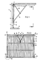
- the swing gate designated overall by 5, is attached in the region of each opening of a building, indicated schematically by 6, and has a frame frame 7, consisting of two spaced-apart vertical parts 8 and a horizontal part 9 connecting these two, and one by a lever 10 spring-loaded door leaf 11, which is shown in the partially open state.
- the levers 10 act on the one hand approximately in the central region of the door leaf on each side, on the other hand in the vicinity of the upper ends of the vertical parts 8 of the frame frame.
- the door leaf 11 has two laterally projecting guide rollers 12, the axes 13 (FIG. 3) of which are arranged in alignment with one another and are guided or guided on guide surfaces 14 formed by the vertical parts 8 of the frame frame 7 and pointing into the interior of the garage 1, the positions of the lever 10 and the door leaf 11 are shown in the open state.
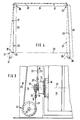
- FIG. 3 show the guide roller 12 arranged in the lower region of the door leaf 11, the axis 13 of which is fixed to the guide roller bearing 18 and which projects laterally beyond the door leaf 11. It can be seen that the axis 13 of the guide roller 12 runs horizontally and in the plane of the door leaf 11. On the axis 13, the one loop-shaped ends 19, 20 of two ropes 21, 22 are shown, the courses of which are described in more detail below (FIG. 4).
- the first rope 22 is parallel to a guide surface 14 in a first section 23 vertically upwards and deflected there by 90 ° by means of an upper deflection roller 28 which is arranged in the region of the one upper corner 27 of the frame frame 7. From there, the rope 22 runs in a second section parallel to the horizontally running part 9 of the Frame frame 7 approximately horizontally to the other upper deflection roller 29, which is arranged in the area of the other upper corner 27 of the frame frame 7, and is deflected by this again by 90 °, so that it is approximately parallel to the first section 23 in a third section 25 and guided parallel to the plane of the guide surface 14 up to a lower deflection roller designated 30 and deflected there approximately by a double right angle, which is rotatably mounted in the lower end region of the other guide surface 14 of the vertical part 8 of the frame frame 7.
- the cable 22 is guided from this roller 30 in a fourth section 26 into the area of the other deflection roller 12 and is preferably also fixed to the axis 13 of the guide roller 12 by means of a loop (cf. FIG. 3).
- one end 20 of the rope 22 and the other end thereof must be fixed at approximately the same height as the door leaf 11, preferably directly on the axis 13 of the guide roller 12.
- One end 19 of the second rope 21 is, as shown in FIG. 3, in the opposite direction to the rope 22, but parallel to it in a fourth section 26 down to a deflection roller 31, deflected by this by an approximately double right angle and in a third section 25 to one upper deflection roller 28, deflected there by approximately a right angle and extending in a second section 24 to the other upper deflection roller 29, from this in turn 90 ° in a first section 23 to the other (Fig. 2 right) guided guide roller 12 and fixed there equally.
- the axes 32 (FIG. 3) of all deflecting rollers 28 - 31 are parallel to one another and perpendicular to the plane of the guide surface 14 and also perpendicular to the axis 13 of each guide roller 12. So that the two cables 21, 22 can be deflected without problems, the two are upper guide rollers 28, 29 formed as double rollers with a common axis of rotation.
Landscapes
- Engineering & Computer Science (AREA)
- Mechanical Engineering (AREA)
- Power-Operated Mechanisms For Wings (AREA)
- Closing And Opening Devices For Wings, And Checks For Wings (AREA)
- Operating, Guiding And Securing Of Roll- Type Closing Members (AREA)
- Securing Of Glass Panes Or The Like (AREA)
- Door And Window Frames Mounted To Openings (AREA)
- Gates (AREA)
Description
- Die Erfindung betrifft ein Schwingtor, insbesondere für Garagen, gemäss dem Oberbegriff des Anspruchs 1.
- Diese Gattung von Schwingtoren zeichnet sich vornehmlich dadurch aus, dass die Unterkante des Torblattes praktisch kaum aus der durch den geschlossenen Zustand des Torblattes festgelegten Ebene herausschwingt beim Öffnen, was in manchen Ländern Vorschrift ist. Das hierbei auftretende Problem besteht darin, dass normale Torblätter nicht ausreichend verwindungssteif sind, so dass bei Betätigung des Torblattes Probleme auftreten können.
- Zur Versteifung solcher Torblätter ist deshalb ein gattungsgemässes Schwingtor gemäss dem Oberbegriff des Anspruchs 1 bekannt geworden (DE-GM 7 238 251), bei dem die Führungsrollen an den Enden einer gemeinsamen, sich über die gesamte Breite des Torblattes erstreckenden Achse angebracht sind. Infolgedessen hat das Torblatt eine bessere Verwindungssteifigkeit. Diese bekannten Torblätter haben sich bewährt, wenn beim Öffnen oder Schliessen des Torblattes dieses etwa in der Mitte seiner Breite angefasst und betätigt wird. Sobald aber ein Benutzer aussermittig an diesem gattungsgemässen Torblatt angreift, verkantet es sich sofort und sperrt infolgedessen, weil der Parallellauf der Führungsrollen an den Führungsflächen nicht mehr sichergestellt ist.
- Der Erfindung liegt die Aufgabe zugrunde, ein gattungsgemässes Schwingtor insbesondere für Garagen gemäss dem Oberbegriff des Anspruchs 1 in einfacher Weise so auszubilden, dass eine zuverlässige Funktion beim Öffnen und Schliessen des Torblattes sichergestellt ist, ohne dass es verkantet und infolgedessen sperrt.
- Diese Aufgabe wird bei einem gattungsgemässen handbetätigten Schwingtor gemäss dem Oberbegriff des Hauptanspruchs erfindungsgemäss durch dessen kennzeichnende Merkmale gelöst.
- Durch die beiden Seile, die im Bereich jeder Führungsrolle, vorzugsweise an deren Achsen angreifen und in vier Teilstücken, praktisch in einer Ebene liegend um den lichten Öffnungsquerschnitt des Torblattes nach der erfindungsgemässen Lehre herumgeführt sind, ist sichergestellt, dass die Unterkante des Torblattes bzw. die Verbindungslinie zwischen den beiden Anlenkpunkten jedes Endes des Seiles auf verschiedenen Seiten des Torblattes immer parallel zu sich selbst infolge der Zwangsführung der Seile beim Öffnen oder Schliessen von Hand bewegt wird. Hierdurch bedingt, kann selbst ein aussermittiges Angreifen und Betätigen des Torblattes mit der Hand zum Öffnen oder Schliessen im Gegensatz zum Stand der Technik nicht zu einem Verkanten oder Sperren führen. Infolge der einfachen Ausbildung mittels eines Seiles und mehreren Rollen können auch schon montierte Schwingtore schnell und unkompliziert mit der Erfindung nachgerüstet werden, zumal dafür keine Einbautiefe erforderlich ist, sondern die Umlenkrollen am Zargenrahmen selbst auf dessen Innenseite in Höhe der Führungsfläche angeordnet werden können. In jedem Falle wird erfindungsgemäss in einfacher Weise bei gattungsgemässen Toren erreicht, dass diese ohne besondere Aufmerksamkeit immer störungs- und problemfrei und damit hinreichend zuverlässig von Hand betätigt werden können, ohne dass ein Verkanten oder Sperren dabei auftritt.
- Zweckmässige Ausgestaltungen und Weiterbildungen der Erfindung sind in den Unteransprüchen gekennzeichnet.
- Ein bevorzugtes Ausführungsbeispiel der Erfindung wird nachfolgend anhand der Zeichnungen näher erläutert.
- Es zeigt:
- Fig. 1 ein Schwingtor in halbgeöffneter Stellung im schematischen Querschnitt;
- Fig. 2 eine Ansicht 11-11 gemäss Fig. 1;
- Fig. 3 die Einzelheit 111 gemäss Fig. 2, in teilweise abgebrochener Ansicht und grösserem Massstab und
- Fig. 4 den Verlauf der Seile gemäss Fig. 2.
- Das insgesamt mit 5 bezeichnete Schwingtor ist im Bereich jeder Öffnung eines schematisch mit 6 bezeichneten Gebäudes angebracht und weist einen Zargenrahmen 7, bestehend aus zwei mit Abstand voneinander angeordneten lotrechten Teilen 8 und aus einem diese beiden verbindenden horizontalen Teil 9, und ein durch einen Hebel 10 federbetastet gehaltenes Torblatt 11 auf, welches im teilweise geöffneten Zustand dargestellt ist. Die Hebel 10 greifen einerseits etwa im mittleren Bereich des Torblattes an jeder Seite, andererseits in der Nähe der oberen Enden der senkrechten Teile 8 des Zargenrahmens an.
- Weiterhin weist das Torblatt 11 zwei über dieses seitlich herausragende Führungsrollen 12 auf, deren Achsen 13 (Fig. 3) zueinander fluchtend angeordnet sind und an von den lotrechten Teilen 8 des Zargenrahmens 7 gebildeten, in das Garageninnere weisenden Führungsflächen 14 geführt sind, bzw. sich daran abstützend in der gestrichelt eingezeichneten Lage gemäss Fig. 1 sind die Lagen des Hebels 10 und des Torblattes 11 im geöffneten Zustand dargestellt.
- Fig. 2 zeigt demgegenüber das Schwingtor 5 mit geschlossenem Torblatt 11 vom Innern des Gebäudes 6 nach aussen gesehen, wobei die Hebel 10 zur besseren zeichnerischen Darstellung nicht voll ausgezeichnet, sondern abgebrochen dargestellt sind. Ferner ist das Schloss 15 mit den beiden Schliessstangen 16 und Riegeln 17 ersichtlich.
- Die grösser dargestellten Einzelheiten gemäss Fig. 3 zeigen die im unteren Bereich des Torblattes 11 angeordnete Führungsrolle 12, deren Achse 13 an dem Führungsrollenlager 18 festgelegt ist und die seitlich über das Torblatt 11 heraussteht. Es ist ersichtlich, dass die Achse 13 der Führungsrolle 12 waagrecht und in der Ebene des Torblattes 11 verläuft. An der Achse 13 sind die einen schlingenförmigen Enden 19, 20 von zwei Seilen 21, 22 gezeigt, deren Verläufe nachfolgend näher beschrieben werden (Fig. 4).
- Das erste Seil 22 ist in einem ersten Teilstück 23 parallel zur einen Führungsfläche 14 lotrecht nach oben und dort um 90° mittels einer oberen Umlenkrolle 28 umgelenkt, die im Bereich der einen oberen Ecke 27 des Zargenrahmens 7 angeordnet ist. Von dort aus verläuft das Seil 22 in einem zweiten Teilstück parallel zum horizontal verlaufenden Teil 9 des Zargenrahmens 7 etwa horizontal bis zur anderen oberen Umlenkrolle 29, die im Bereich der anderen oberen Ecke 27 des Zargenrahmens 7 angeordnet ist, und wird von dieser um wiederum 90° umgelenkt, so dass es in einem dritten Teilstück 25 etwa parallel zu dem ersten Teilstück 23 und parallel zu der Ebene der Führungsfläche 14 bis zu einer mit 30 bezeichneten unteren Umlenkrolle geführt und dort etwa um einen doppelten rechten Winkel umgelenkt, die im unteren Endbereich der anderen Führungsfläche 14 des lotrechten Teiles 8 des Zargenrahmens 7 drehbar gelagert ist. Von dieser Rolle 30 ist das Seil 22 in einem vierten Teilstück 26 bis in den Bereich der anderen Umlenkrolle 12 geführt und vorzugsweise auch mittels einer Schlinge an der Achse 13 der Führungsrolle 12 festgelegt (vgl. Fig. 3). Jedenfalls müssen das eine Ende 20 des Seiles 22 und dessen anderes Ende in etwa in derselben Höhe des Torblattes 11 festgelegt werden, vorzugsweise direkt an der Achse 13 der Führungsrolle 12.
- Das eine Ende 19 des zweiten Seiles 21 ist, wie Fig. 3 zeigt, in entgegengesetzter Richtung wie das Seil 22, aber parallel zu diesen in einem vierten Teilstück 26 nach unten zu einer Umlenkrolle 31 geführt, von dieser um einen etwa doppelten rechten Winkel umgelenkt und in einem dritten Abschnitt 25 bis zu der einen oberen Umlenkrolle 28 geführt, dort um etwa einen rechten Winkel umgelenkt und in einem zweiten Teilstück 24 bis zur anderen oberen Umlenkrolle 29 verlaufend, von dieser um wiederum 90° in einem ersten Teilstück 23 zu der anderen (Fig. 2 rechten) Führungsrolle 12 geführt und dort gleichermassen festgelegt.
- Die Achsen 32 (Fig. 3) aller Umlenkrollen 28 - 31 sind parallel zueinander und senkrecht zu der Ebene der Führungsfläche 14 und ebenso senkrecht zu der Achse 13 jeder Führungsrolle 12. Damit die beiden Seile 21, 22 problemlos umgelenkt werden können, sind die beiden oberen Umlenkrollen 28, 29 als Doppelrollen mit gemeinsamer Drehachse ausgebildet.
- Durch diese Ausbildung und Geometrie und Führung der Teilstücke jedes Seiles und der auf der Geraden 33 (Fig. 3 und 4) liegenden Enden 19, 20 der beiden Seile 20, 21 ist sichergestellt, dass jede Führungsrolle 12 einer Zwangsführung dergestalt unterliegt und sie stets längs der sich parallel verschiebenden Linie 33 beim Öffnen und Schliessen des Torblattes 11 verlaufen, ein Verkanten und Sperren demgemäss nach Lehre der Erfindung nicht möglich ist.
Claims (3)
Priority Applications (1)
| Application Number | Priority Date | Filing Date | Title |
|---|---|---|---|
| AT83108836T ATE19422T1 (de) | 1982-09-08 | 1983-09-07 | Schwingtor, insbesondere fuer garagen. |
Applications Claiming Priority (2)
| Application Number | Priority Date | Filing Date | Title |
|---|---|---|---|
| DE3233350 | 1982-09-08 | ||
| DE3233350A DE3233350C2 (de) | 1982-09-08 | 1982-09-08 | Schwingtor, insbesondere für Garagen |
Publications (2)
| Publication Number | Publication Date |
|---|---|
| EP0103269A1 EP0103269A1 (de) | 1984-03-21 |
| EP0103269B1 true EP0103269B1 (de) | 1986-04-23 |
Family
ID=6172733
Family Applications (1)
| Application Number | Title | Priority Date | Filing Date |
|---|---|---|---|
| EP83108836A Expired EP0103269B1 (de) | 1982-09-08 | 1983-09-07 | Schwingtor, insbesondere für Garagen |
Country Status (5)
| Country | Link |
|---|---|
| EP (1) | EP0103269B1 (de) |
| AT (1) | ATE19422T1 (de) |
| CA (1) | CA1260319A (de) |
| DE (2) | DE3233350C2 (de) |
| ES (1) | ES274262Y (de) |
Family Cites Families (7)
| Publication number | Priority date | Publication date | Assignee | Title |
|---|---|---|---|---|
| FR1174156A (fr) * | 1956-04-13 | 1959-03-06 | Construction et mécanisme et procédé de déplacement d'une cloison | |
| DE7202694U (de) * | 1971-04-29 | 1972-04-13 | Srl Cir | Federvorrichtung zum betaetigen von pendeltueren |
| DE7238251U (de) * | 1972-10-18 | 1973-02-15 | Hoermann Kg | Garagenschwingtor |
| DE7238252U (de) * | 1972-10-18 | 1973-02-15 | Hoermann Kg | Garagenschwingtor |
| DE2549395A1 (de) * | 1974-11-05 | 1976-05-13 | Mewald Franz Ing | Einrichtung zum oeffnen von toren |
| DE2627894A1 (de) * | 1976-06-22 | 1978-01-05 | Hans Juergen Dr Ing Reinhard | Garagentor |
| GB2073814B (en) * | 1980-04-03 | 1983-10-12 | Garage Door Automation Ltd | Apparatus for opening and closing a panel in a frame |
-
1982
- 1982-09-08 DE DE3233350A patent/DE3233350C2/de not_active Expired
-
1983
- 1983-09-07 CA CA000436159A patent/CA1260319A/en not_active Expired
- 1983-09-07 ES ES1983274262U patent/ES274262Y/es not_active Expired
- 1983-09-07 DE DE8383108836T patent/DE3363182D1/de not_active Expired
- 1983-09-07 AT AT83108836T patent/ATE19422T1/de not_active IP Right Cessation
- 1983-09-07 EP EP83108836A patent/EP0103269B1/de not_active Expired
Also Published As
| Publication number | Publication date |
|---|---|
| ATE19422T1 (de) | 1986-05-15 |
| DE3363182D1 (en) | 1986-05-28 |
| ES274262Y (es) | 1984-11-16 |
| ES274262U (es) | 1984-04-01 |
| EP0103269A1 (de) | 1984-03-21 |
| DE3233350A1 (de) | 1984-03-08 |
| CA1260319A (en) | 1989-09-26 |
| DE3233350C2 (de) | 1984-11-15 |
Similar Documents
| Publication | Publication Date | Title |
|---|---|---|
| EP0230999B1 (de) | Deckengliedertor für niedrige Sturzhöhen | |
| DE19652577C2 (de) | Sektionaltor zum Verschließen einer Wandöffnung | |
| EP3296500A1 (de) | Tor | |
| CH714546B1 (de) | Vorrichtung zum Öffnen einer Gebäudedachöffnung. | |
| DE3233350C2 (de) | Schwingtor, insbesondere für Garagen | |
| EP0976904B1 (de) | Vorrichtung zum Verschliessen einer Wandöffnung | |
| EP0675253A1 (de) | Sektionaltor | |
| DE102010043821A1 (de) | Verriegelungseinrichtung für ein Seitensektionaltor | |
| DE8225324U1 (de) | Schwingtor, insbesondere fuer garagen | |
| DE102020116927A1 (de) | Abschlusselement und Tor mit einem Abschlusselement | |
| DE10111903B4 (de) | Abschlusselement für Wandöffnungen | |
| EP4336007B1 (de) | Beschlag für eine schiebetür sowie schiebetür | |
| DE10122526B4 (de) | Karusselltür mit Nachtabschluss | |
| AT396504B (de) | Schiebetor | |
| WO2005090734A1 (de) | Vorrichtung zum verschluss und/oder zum schutz von bauwerksöffnungen | |
| DE2521614A1 (de) | Fluegeltor fuer garagen | |
| DE2645671A1 (de) | Deckengliedertor | |
| EP1932999A2 (de) | Seitensektionaltor | |
| DE19630266C2 (de) | Toraggregat | |
| DE2110862C2 (de) | Schwingflügellager | |
| DE1951657A1 (de) | Tor fuer Hallen,Garagen od.dgl. | |
| AT516842B1 (de) | Türblatt | |
| DE202005020731U1 (de) | Tor-Vorrichtung | |
| DE202012104932U1 (de) | Türe, die in beide Richtungen geöffnet werden kann | |
| DE2028264A1 (de) | Vertikales Schiebefenster |
Legal Events
| Date | Code | Title | Description |
|---|---|---|---|
| PUAI | Public reference made under article 153(3) epc to a published international application that has entered the european phase |
Free format text: ORIGINAL CODE: 0009012 |
|
| AK | Designated contracting states |
Designated state(s): AT BE CH DE FR GB IT LI NL SE |
|
| 17P | Request for examination filed |
Effective date: 19840330 |
|
| RBV | Designated contracting states (corrected) |
Designated state(s): AT BE CH DE FR GB IT LI NL SE |
|
| ITF | It: translation for a ep patent filed | ||
| GRAA | (expected) grant |
Free format text: ORIGINAL CODE: 0009210 |
|
| AK | Designated contracting states |
Kind code of ref document: B1 Designated state(s): AT BE CH DE FR GB IT LI NL SE |
|
| REF | Corresponds to: |
Ref document number: 19422 Country of ref document: AT Date of ref document: 19860515 Kind code of ref document: T |
|
| REF | Corresponds to: |
Ref document number: 3363182 Country of ref document: DE Date of ref document: 19860528 |
|
| ET | Fr: translation filed | ||
| PLBE | No opposition filed within time limit |
Free format text: ORIGINAL CODE: 0009261 |
|
| STAA | Information on the status of an ep patent application or granted ep patent |
Free format text: STATUS: NO OPPOSITION FILED WITHIN TIME LIMIT |
|
| 26N | No opposition filed | ||
| ITTA | It: last paid annual fee | ||
| EAL | Se: european patent in force in sweden |
Ref document number: 83108836.4 |
|
| PGFP | Annual fee paid to national office [announced via postgrant information from national office to epo] |
Ref country code: FR Payment date: 19980804 Year of fee payment: 16 |
|
| PGFP | Annual fee paid to national office [announced via postgrant information from national office to epo] |
Ref country code: SE Payment date: 19980817 Year of fee payment: 16 |
|
| PGFP | Annual fee paid to national office [announced via postgrant information from national office to epo] |
Ref country code: GB Payment date: 19980824 Year of fee payment: 16 |
|
| PGFP | Annual fee paid to national office [announced via postgrant information from national office to epo] |
Ref country code: BE Payment date: 19980831 Year of fee payment: 16 |
|
| PGFP | Annual fee paid to national office [announced via postgrant information from national office to epo] |
Ref country code: CH Payment date: 19980908 Year of fee payment: 16 |
|
| PGFP | Annual fee paid to national office [announced via postgrant information from national office to epo] |
Ref country code: AT Payment date: 19980914 Year of fee payment: 16 |
|
| PGFP | Annual fee paid to national office [announced via postgrant information from national office to epo] |
Ref country code: NL Payment date: 19980930 Year of fee payment: 16 |
|
| PGFP | Annual fee paid to national office [announced via postgrant information from national office to epo] |
Ref country code: DE Payment date: 19981127 Year of fee payment: 16 |
|
| PG25 | Lapsed in a contracting state [announced via postgrant information from national office to epo] |
Ref country code: GB Free format text: LAPSE BECAUSE OF NON-PAYMENT OF DUE FEES Effective date: 19990907 Ref country code: AT Free format text: LAPSE BECAUSE OF NON-PAYMENT OF DUE FEES Effective date: 19990907 |
|
| PG25 | Lapsed in a contracting state [announced via postgrant information from national office to epo] |
Ref country code: SE Free format text: THE PATENT HAS BEEN ANNULLED BY A DECISION OF A NATIONAL AUTHORITY Effective date: 19990929 |
|
| PG25 | Lapsed in a contracting state [announced via postgrant information from national office to epo] |
Ref country code: LI Free format text: LAPSE BECAUSE OF NON-PAYMENT OF DUE FEES Effective date: 19990930 Ref country code: CH Free format text: LAPSE BECAUSE OF NON-PAYMENT OF DUE FEES Effective date: 19990930 Ref country code: BE Free format text: LAPSE BECAUSE OF NON-PAYMENT OF DUE FEES Effective date: 19990930 |
|
| BERE | Be: lapsed |
Owner name: HORMANN K.G. AMSHAUSEN Effective date: 19990930 |
|
| PG25 | Lapsed in a contracting state [announced via postgrant information from national office to epo] |
Ref country code: NL Free format text: LAPSE BECAUSE OF NON-PAYMENT OF DUE FEES Effective date: 20000401 |
|
| GBPC | Gb: european patent ceased through non-payment of renewal fee |
Effective date: 19990907 |
|
| EUG | Se: european patent has lapsed |
Ref document number: 83108836.4 |
|
| REG | Reference to a national code |
Ref country code: CH Ref legal event code: PL |
|
| PG25 | Lapsed in a contracting state [announced via postgrant information from national office to epo] |
Ref country code: FR Free format text: LAPSE BECAUSE OF NON-PAYMENT OF DUE FEES Effective date: 20000531 |
|
| NLV4 | Nl: lapsed or anulled due to non-payment of the annual fee |
Effective date: 20000401 |
|
| PG25 | Lapsed in a contracting state [announced via postgrant information from national office to epo] |
Ref country code: DE Free format text: LAPSE BECAUSE OF NON-PAYMENT OF DUE FEES Effective date: 20000701 |
|
| REG | Reference to a national code |
Ref country code: FR Ref legal event code: ST |