EP0102304A1 - Elektronische Kraftstoffeinspritzvorrichtung für eine Brennkraftmaschine - Google Patents
Elektronische Kraftstoffeinspritzvorrichtung für eine Brennkraftmaschine Download PDFInfo
- Publication number
- EP0102304A1 EP0102304A1 EP83420130A EP83420130A EP0102304A1 EP 0102304 A1 EP0102304 A1 EP 0102304A1 EP 83420130 A EP83420130 A EP 83420130A EP 83420130 A EP83420130 A EP 83420130A EP 0102304 A1 EP0102304 A1 EP 0102304A1
- Authority
- EP
- European Patent Office
- Prior art keywords
- drawer
- sheath
- injection
- injector
- slides
- Prior art date
- Legal status (The legal status is an assumption and is not a legal conclusion. Google has not performed a legal analysis and makes no representation as to the accuracy of the status listed.)
- Withdrawn
Links
Images


Classifications
-
- F—MECHANICAL ENGINEERING; LIGHTING; HEATING; WEAPONS; BLASTING
- F02—COMBUSTION ENGINES; HOT-GAS OR COMBUSTION-PRODUCT ENGINE PLANTS
- F02M—SUPPLYING COMBUSTION ENGINES IN GENERAL WITH COMBUSTIBLE MIXTURES OR CONSTITUENTS THEREOF
- F02M47/00—Fuel-injection apparatus operated cyclically with fuel-injection valves actuated by fluid pressure
- F02M47/02—Fuel-injection apparatus operated cyclically with fuel-injection valves actuated by fluid pressure of accumulator-injector type, i.e. having fuel pressure of accumulator tending to open, and fuel pressure in other chamber tending to close, injection valves and having means for periodically releasing that closing pressure
- F02M47/027—Electrically actuated valves draining the chamber to release the closing pressure
Definitions
- the present invention relates to an electronic injection device intended to ensure the injection of fuel into an internal combustion engine, and more particularly into a piston engine.
- a so-called double-drawer injection device in which the high pressure is established in the fuel at each of the two ends of the injection needle.
- the start of injection is triggered. Indeed, the needle then lifts from its seat, due to the high pressure which continues to prevail on this side.
- each of the drawers is controlled separately by the action of medium-pressure diesel, delivered by micro-valves themselves controlled by an electronic computer.
- the object of the present invention is to avoid this drawback, by producing a device in which the start and end of the injection are no longer controlled but the start and the duration of the injection.
- An electronic injection device comprises sliding dispensing members interposed on the high pressure fuel circuit, linked to the two ends of the needle of an injector, and it is characterized in that the two dispensing members are constituted by a sliding drawer inside a sheath which in turn slides in the body of a dispenser, the longitudinal sliding of the drawer and the sheath being controlled independently of one another.
- the drawer travels a round trip for each combustion cycle.
- the drawer travels only a single stroke for each combustion cycle.
- the drawer travels at least one stroke during each combustion cycle, while the sheath is only moved when it is desired to modify the injected flow rate.
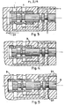
- FIG. 1 the silhouette of a Diesel 1 core, with four cylinders.
- Line 2 ensures the arrival of diesel fuel from the tank to a filter 3 of known type.
- a booster pump 4 sends the fuel to a pump-distributor 5 that high-pressure pipes 6 connect to each of the injection systems 7 with which each cylinder is provided.
- Each injection system 7 comprises, in known manner, an injector whose needle is subjected at each end to the high pressure.
- each system 7 also comprises an injection device of the kind which will be described with reference to Figures 2 to 17.
- This device comprises a distributor-drawer 8, capable of sliding in the longitudinal direction inside a cylindrical sheath 9, which in turn slides in the fixed body 10 of the device .
- the sheath 9 is pierced with two orifices 15 and 16 which pass through it diametrically.
- diametric holes 17 are provided opposite in the body 10, to ensure the junction with the connecting pipes 22, 23, 24
- Inner passages 26 and 27 communicate, respectively, the hole 17 with the hole 20, then the hole 18 with the hole 19.
- Line 24 joins one end of the three holes 19, 20 and 21.
- Line 24 is connected to the rear face of the injector needle of known type, not shown.
- the pipes 25 and 22 are connected to the high pressure pump 5.
- the pipe 23 is connected to the diesel tank, that is to say that it constitutes the discharge.
- the groove 11 is capable of closing off or of discovering more or less the section of the diametral bore 17. The same is true for the groove 12 relative to the bore 18, for the groove 13 relative to the bore 19, and for the throat 14 with respect to all of the two holes 20 and 21.
- the groove 14 of the drawer 8 puts the lines 24 and 25 into communication: the rear face of the injector needle is therefore under pressure, and there is no injection .
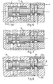
- the slide 8 begins to move to the left (FIG. 8) at a substantially constant speed, whatever the load and the engine speed.
- the drawer 8 closes the bore 21, which cuts the communication between the pipes 24 and 25.
- the groove 13 arrives opposite the bore 19 which it unmasks (FIG. 11), which connects the line 24 of the injector, to the discharge line 23, through the groove 12 and the bore 16 which are then in coincidence: the injector needle can now lift from its seat, which corresponds to the beginning of the injection.
- Drawer and scabbard are actuated by 1 ' intermediate, either of a hydraulic control, or of an electro-mechanical control and, in both cases, with or without return spring.
- the injector opening and injection duration orders are dependent on a computer whose input parameters represent the operating conditions and / or the orders received from the driver, and whose outputs are defined from of these inputs, by means of a suitable algorithm ensuring the operation of the computer.
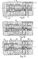
- next injection can be made in a similar way during the movement of the drawer from left to right, in which case, in the description above, the relative position of the parts which corresponded to the start of the connection of the discharge with the face rear of the injector becomes the end, and vice versa.
- next injection can also be done strictly identical to the previous one, if, between two injections, the drawer returns to its initial position (on the right), corresponding to the start of the first phase.
- an additional device between the device which has just been described and the injector, so that, during the return stroke of the slide, the rear face of the needle remains constantly subjected to high pressure.
- This additional device could be a distributor playing the role of a three-way valve connecting the injector to the device object of the invention, during the injection phase and to a high pressure source between two injection phases, the communication being controlled by the calculator or any suitable means.
Landscapes
- Engineering & Computer Science (AREA)
- Physics & Mathematics (AREA)
- Fluid Mechanics (AREA)
- Chemical & Material Sciences (AREA)
- Combustion & Propulsion (AREA)
- Mechanical Engineering (AREA)
- General Engineering & Computer Science (AREA)
- Fuel-Injection Apparatus (AREA)
Applications Claiming Priority (2)
| Application Number | Priority Date | Filing Date | Title |
|---|---|---|---|
| FR8213138 | 1982-07-22 | ||
| FR8213138A FR2530734A1 (fr) | 1982-07-22 | 1982-07-22 | Dispositif pour l'injection electronique du combustible d'un moteur a combustion interne |
Publications (1)
| Publication Number | Publication Date |
|---|---|
| EP0102304A1 true EP0102304A1 (de) | 1984-03-07 |
Family
ID=9276380
Family Applications (1)
| Application Number | Title | Priority Date | Filing Date |
|---|---|---|---|
| EP83420130A Withdrawn EP0102304A1 (de) | 1982-07-22 | 1983-07-20 | Elektronische Kraftstoffeinspritzvorrichtung für eine Brennkraftmaschine |
Country Status (4)
| Country | Link |
|---|---|
| US (1) | US4604981A (de) |
| EP (1) | EP0102304A1 (de) |
| ES (1) | ES8403570A1 (de) |
| FR (1) | FR2530734A1 (de) |
Families Citing this family (5)
| Publication number | Priority date | Publication date | Assignee | Title |
|---|---|---|---|---|
| DE3614495A1 (de) * | 1986-04-29 | 1987-11-05 | Kloeckner Humboldt Deutz Ag | Kraftstoffeinspritzvorrichtung fuer eine brennkraftmaschine |
| US5299919A (en) * | 1991-11-01 | 1994-04-05 | Paul Marius A | Fuel injector system |
| NL9402238A (nl) * | 1994-12-29 | 1996-08-01 | Adrianus Martinus M Wildenberg | Fluidumdoseerinrichting. |
| US6092546A (en) * | 1997-12-12 | 2000-07-25 | Alliedsignal Inc. | Fuel flow divider and pressurizing valve for gas turbine |
| DE10054202A1 (de) * | 2000-11-02 | 2002-05-29 | Siemens Ag | Injektor zum Einspritzen von Kraftstoff in einen Brennraum |
Citations (3)
| Publication number | Priority date | Publication date | Assignee | Title |
|---|---|---|---|---|
| DE2433309A1 (de) * | 1974-07-08 | 1976-01-29 | Sulzer Ag | Steuerschieber fuer eine brennstoffeinspritzvorrichtung einer dieselbrennkraftmaschine |
| US3983855A (en) * | 1973-07-12 | 1976-10-05 | C.A.V. Limited | Fuel injection system |
| FR2328853A1 (fr) * | 1975-10-24 | 1977-05-20 | Karl Marx Stadt Automobilbau | Soupape electromagnetique d'injection pour moteurs a combustion interne avec une soupape a plusieurs voies commandee electromagnetiquement pour la charge et la decharge du cote arriere de l'aiguille d'injection |
Family Cites Families (5)
| Publication number | Priority date | Publication date | Assignee | Title |
|---|---|---|---|---|
| US20254A (en) * | 1858-05-18 | Railroad-car for day and ntght service | ||
| US2827030A (en) * | 1955-11-22 | 1958-03-18 | Strumbos William | Fuel injection means for internal combustion engines |
| US3187733A (en) * | 1963-08-23 | 1965-06-08 | Int Harvester Co | Fuel injection system for internal combustion engines |
| GB1148905A (en) * | 1965-10-05 | 1969-04-16 | Cav Ltd | Improvements in or relating to fuel injection pumps |
| US3851635A (en) * | 1969-05-14 | 1974-12-03 | F Murtin | Electronically controlled fuel-supply system for compression-ignition engine |
-
1982
- 1982-07-22 FR FR8213138A patent/FR2530734A1/fr active Granted
-
1983
- 1983-07-20 EP EP83420130A patent/EP0102304A1/de not_active Withdrawn
- 1983-07-20 US US06/516,114 patent/US4604981A/en not_active Expired - Fee Related
- 1983-07-21 ES ES524341A patent/ES8403570A1/es not_active Expired
Patent Citations (3)
| Publication number | Priority date | Publication date | Assignee | Title |
|---|---|---|---|---|
| US3983855A (en) * | 1973-07-12 | 1976-10-05 | C.A.V. Limited | Fuel injection system |
| DE2433309A1 (de) * | 1974-07-08 | 1976-01-29 | Sulzer Ag | Steuerschieber fuer eine brennstoffeinspritzvorrichtung einer dieselbrennkraftmaschine |
| FR2328853A1 (fr) * | 1975-10-24 | 1977-05-20 | Karl Marx Stadt Automobilbau | Soupape electromagnetique d'injection pour moteurs a combustion interne avec une soupape a plusieurs voies commandee electromagnetiquement pour la charge et la decharge du cote arriere de l'aiguille d'injection |
Also Published As
| Publication number | Publication date |
|---|---|
| FR2530734A1 (fr) | 1984-01-27 |
| ES524341A0 (es) | 1984-04-16 |
| US4604981A (en) | 1986-08-12 |
| FR2530734B1 (de) | 1984-12-14 |
| ES8403570A1 (es) | 1984-04-16 |
Similar Documents
| Publication | Publication Date | Title |
|---|---|---|
| FR2593239A1 (fr) | Systeme d'injection de carburant pour moteur a combustion interne | |
| FR2520892A1 (fr) | Systeme regulateur de la vitesse d'un moteur | |
| CH644187A5 (fr) | Dispositif d'injection de combustible, notamment pour des moteurs diesel. | |
| FR2473633A1 (fr) | Installation d'injection de carburant pour moteurs a combustion interne a auto-allumage | |
| EP0526616B1 (de) | Kraftstoffeinspritzvorrichtung für Verbrennungsmotoren | |
| FR2581704A1 (fr) | Dispositif d'injection de carburant pour moteurs a combustion interne a auto-allumage | |
| CA1112056A (fr) | Methode et dispositif pour ameliorer le fonctionnement d'un moteur equipe d'un turbo- compresseur | |
| FR2529260A1 (fr) | Pompe d'injection de carburant repartitrice | |
| EP0102304A1 (de) | Elektronische Kraftstoffeinspritzvorrichtung für eine Brennkraftmaschine | |
| EP0898649B1 (de) | Flüssigkraftstoffeinspritzvorrichtung für verbrennungsmotor | |
| FR2497294A1 (fr) | Systeme d'injection de carburant | |
| EP0150138A2 (de) | Sicherheitsvorrichtung für Gleichdruckeinspritzventil einer Brennkraftmaschine | |
| FR2883044A1 (fr) | Injecteur de carburant pour moteur a combustion interne | |
| FR2889259A3 (fr) | Rampe commune d'alimentation en carburant pour vehicule a pression variable | |
| FR2816665A1 (fr) | Injecteur a dispositif de commande en cascade et alimente a partir d'une rampe commune | |
| FR2508548A1 (fr) | Dispositif pour limiter le debit d'injection de combustible dans un moteur diesel | |
| FR2794496A1 (fr) | Selecteur de cylindree pour un moteur hydraulique evitant un freinage brutal lors du passage de petite cylindree en grande cylindree | |
| FR2889260A3 (fr) | Rampe commune d'alimentation en carburant pour moteur, comprenant deux chambres | |
| EP0089301A1 (de) | Einspritzsteueranlage für Dieselmotoren | |
| FR2608684A1 (fr) | Pompe d'injection de carburant pour moteur a combustion interne avec coupure par etranglement sur le canal de decharge, en fonction de la charge | |
| EP0030907A1 (de) | Kraftstoffeinspritzvorrichtung für eine Brennkraftmaschine | |
| EP0056916B1 (de) | Vorrichtung zur Brennstoffeinspritzung in einen Verbrennungsmotor | |
| WO1998025026A1 (fr) | Dispositif de ralentissement d'ouverture et de reduction de fuite pour systemes d'injection a pression constante utilises sur moteurs diesel | |
| EP0560671A1 (de) | Verteiler für Druckflüssigkeit, insbesondere Schmiermittel in einer Zentralschmieranlage | |
| FR2468743A1 (fr) | Appareil de pompage a injection pour moteur a combustion interne |
Legal Events
| Date | Code | Title | Description |
|---|---|---|---|
| PUAI | Public reference made under article 153(3) epc to a published international application that has entered the european phase |
Free format text: ORIGINAL CODE: 0009012 |
|
| AK | Designated contracting states |
Designated state(s): AT BE CH DE FR GB IT LI LU NL SE |
|
| 17P | Request for examination filed |
Effective date: 19840207 |
|
| STAA | Information on the status of an ep patent application or granted ep patent |
Free format text: STATUS: THE APPLICATION HAS BEEN WITHDRAWN |
|
| 18W | Application withdrawn |
Withdrawal date: 19861122 |
|
| RIN1 | Information on inventor provided before grant (corrected) |
Inventor name: DAZZI, JEAN-LOUIS |