EP0102304A1 - Electronic fuel injection device for an internal-combustion engine - Google Patents
Electronic fuel injection device for an internal-combustion engine Download PDFInfo
- Publication number
- EP0102304A1 EP0102304A1 EP83420130A EP83420130A EP0102304A1 EP 0102304 A1 EP0102304 A1 EP 0102304A1 EP 83420130 A EP83420130 A EP 83420130A EP 83420130 A EP83420130 A EP 83420130A EP 0102304 A1 EP0102304 A1 EP 0102304A1
- Authority
- EP
- European Patent Office
- Prior art keywords
- drawer
- sheath
- injection
- injector
- slides
- Prior art date
- Legal status (The legal status is an assumption and is not a legal conclusion. Google has not performed a legal analysis and makes no representation as to the accuracy of the status listed.)
- Withdrawn
Links
Images


Classifications
-
- F—MECHANICAL ENGINEERING; LIGHTING; HEATING; WEAPONS; BLASTING
- F02—COMBUSTION ENGINES; HOT-GAS OR COMBUSTION-PRODUCT ENGINE PLANTS
- F02M—SUPPLYING COMBUSTION ENGINES IN GENERAL WITH COMBUSTIBLE MIXTURES OR CONSTITUENTS THEREOF
- F02M47/00—Fuel-injection apparatus operated cyclically with fuel-injection valves actuated by fluid pressure
- F02M47/02—Fuel-injection apparatus operated cyclically with fuel-injection valves actuated by fluid pressure of accumulator-injector type, i.e. having fuel pressure of accumulator tending to open, and fuel pressure in other chamber tending to close, injection valves and having means for periodically releasing that closing pressure
- F02M47/027—Electrically actuated valves draining the chamber to release the closing pressure
Definitions
- the present invention relates to an electronic injection device intended to ensure the injection of fuel into an internal combustion engine, and more particularly into a piston engine.
- a so-called double-drawer injection device in which the high pressure is established in the fuel at each of the two ends of the injection needle.
- the start of injection is triggered. Indeed, the needle then lifts from its seat, due to the high pressure which continues to prevail on this side.
- each of the drawers is controlled separately by the action of medium-pressure diesel, delivered by micro-valves themselves controlled by an electronic computer.
- the object of the present invention is to avoid this drawback, by producing a device in which the start and end of the injection are no longer controlled but the start and the duration of the injection.
- An electronic injection device comprises sliding dispensing members interposed on the high pressure fuel circuit, linked to the two ends of the needle of an injector, and it is characterized in that the two dispensing members are constituted by a sliding drawer inside a sheath which in turn slides in the body of a dispenser, the longitudinal sliding of the drawer and the sheath being controlled independently of one another.
- the drawer travels a round trip for each combustion cycle.
- the drawer travels only a single stroke for each combustion cycle.
- the drawer travels at least one stroke during each combustion cycle, while the sheath is only moved when it is desired to modify the injected flow rate.
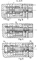
- FIG. 1 the silhouette of a Diesel 1 core, with four cylinders.
- Line 2 ensures the arrival of diesel fuel from the tank to a filter 3 of known type.
- a booster pump 4 sends the fuel to a pump-distributor 5 that high-pressure pipes 6 connect to each of the injection systems 7 with which each cylinder is provided.
- Each injection system 7 comprises, in known manner, an injector whose needle is subjected at each end to the high pressure.
- each system 7 also comprises an injection device of the kind which will be described with reference to Figures 2 to 17.
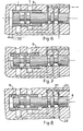
- This device comprises a distributor-drawer 8, capable of sliding in the longitudinal direction inside a cylindrical sheath 9, which in turn slides in the fixed body 10 of the device .
- the sheath 9 is pierced with two orifices 15 and 16 which pass through it diametrically.
- diametric holes 17 are provided opposite in the body 10, to ensure the junction with the connecting pipes 22, 23, 24
- Inner passages 26 and 27 communicate, respectively, the hole 17 with the hole 20, then the hole 18 with the hole 19.
- Line 24 joins one end of the three holes 19, 20 and 21.
- Line 24 is connected to the rear face of the injector needle of known type, not shown.
- the pipes 25 and 22 are connected to the high pressure pump 5.
- the pipe 23 is connected to the diesel tank, that is to say that it constitutes the discharge.
- the groove 11 is capable of closing off or of discovering more or less the section of the diametral bore 17. The same is true for the groove 12 relative to the bore 18, for the groove 13 relative to the bore 19, and for the throat 14 with respect to all of the two holes 20 and 21.
- the groove 14 of the drawer 8 puts the lines 24 and 25 into communication: the rear face of the injector needle is therefore under pressure, and there is no injection .
- the slide 8 begins to move to the left (FIG. 8) at a substantially constant speed, whatever the load and the engine speed.
- the drawer 8 closes the bore 21, which cuts the communication between the pipes 24 and 25.
- the groove 13 arrives opposite the bore 19 which it unmasks (FIG. 11), which connects the line 24 of the injector, to the discharge line 23, through the groove 12 and the bore 16 which are then in coincidence: the injector needle can now lift from its seat, which corresponds to the beginning of the injection.
- Drawer and scabbard are actuated by 1 ' intermediate, either of a hydraulic control, or of an electro-mechanical control and, in both cases, with or without return spring.
- the injector opening and injection duration orders are dependent on a computer whose input parameters represent the operating conditions and / or the orders received from the driver, and whose outputs are defined from of these inputs, by means of a suitable algorithm ensuring the operation of the computer.
- next injection can be made in a similar way during the movement of the drawer from left to right, in which case, in the description above, the relative position of the parts which corresponded to the start of the connection of the discharge with the face rear of the injector becomes the end, and vice versa.
- next injection can also be done strictly identical to the previous one, if, between two injections, the drawer returns to its initial position (on the right), corresponding to the start of the first phase.
- an additional device between the device which has just been described and the injector, so that, during the return stroke of the slide, the rear face of the needle remains constantly subjected to high pressure.
- This additional device could be a distributor playing the role of a three-way valve connecting the injector to the device object of the invention, during the injection phase and to a high pressure source between two injection phases, the communication being controlled by the calculator or any suitable means.
Abstract
L'invention concerne un dispositif distributeur de combustible, dont la canalisation (24) est reliée à l'aiguille d'un injecteur, tandis que la canalisation (23) est reliée à la décharge, et les canalisations (22), (25) à une source de combustible à haute pression. La position du fourreau (9) définit la durée d'injection, c'est-à-dire le débit injecté dont dépend la charge du moteur. Le tiroir (8) se déplace à chaque cycle d'injection. Il est commandé indépendamment du fourreau (9). Application: définition de l'instant de début d'injection, et de la durée de l'injection, ce qui assure une grande reproductibilité de fonctionnent d'un cycle à l'autre.The invention relates to a fuel dispensing device, the line (24) of which is connected to the needle of an injector, the line (23) of which is connected to the discharge, and the lines (22), (25) to a high pressure fuel source. The position of the sleeve (9) defines the duration of injection, that is to say the injected flow on which the engine load depends. The drawer (8) moves with each injection cycle. It is controlled independently of the sheath (9). Application: definition of the injection start time, and the duration of the injection, which ensures high reproducibility of operation from one cycle to another.
Description
La présente invention est relative à un dispositif d'injection électronique destiné à assurer l'injection du combustible dans un moteur à combustion interne, et plus particulièrement dans un moteur à pistons.The present invention relates to an electronic injection device intended to ensure the injection of fuel into an internal combustion engine, and more particularly into a piston engine.
On sait qu'un tel dispositif d'injection doit satisfaire à deux conditions principales , à savoir :
- - doser la quantité de combustible à injecter dans chaque cylindre à chaque cycle , ces dosages étant susceptibles de varier en fonction de la charge souhaitée pour le moteur ;
- - régler l'instant auquel l'injection a lieu par rapport au déroulement de chaque cycle , ceci en fonction de l'avance à l'injection désirée.
- - dose the quantity of fuel to be injected into each cylinder during each cycle, these dosages being liable to vary as a function of the load desired for the engine;
- - set the time at which the injection takes place in relation to the progress of each cycle, this as a function of the advance to the desired injection.
On connaît déjà un dispositif d'injection dit à double tiroir , dans lequel la haute pression s'établit dans le combustible à chacune des deux extrémités de l'aiguille d'injection. Lorsqu'on commande la chute de cette pression derrière l'aiguille , grâce à un déplacement de l' un des deux tiroirs , on déclenche le début d'injection . En effet , l'aiguille se soulève alors de son siège , du fait de la haute pression qui continue à régner de ce côté.A so-called double-drawer injection device is already known, in which the high pressure is established in the fuel at each of the two ends of the injection needle. When controlling the fall of this pressure behind the needle, by means of a displacement of one of the two drawers, the start of injection is triggered. Indeed, the needle then lifts from its seat, due to the high pressure which continues to prevail on this side.
En déplaçant l'autre tiroir , on provoque le rétablissement de la haute pression derrière l'aiguille , ce qui déclenche la fermeture de lfinjecteur avec l'aide de son ressort de tarage : ceci correspond à la fin de l' injection.By moving the other drawer, it causes a return of the high pressure behind the needle, which triggers the closure of f injector with the aid of its calibration spring: this corresponds to the end of the injection.
Dans ce système connu , chacun des tiroirs est commandé séparément par l'action de gazole à moyenne pression , délivré par des micro-valves elles-mêmes pilotées par un calculateur électronique.In this known system, each of the drawers is controlled separately by the action of medium-pressure diesel, delivered by micro-valves themselves controlled by an electronic computer.
Ce système connu permet donc de piloter indépendamment , au moyen d'un calculateur , le début et la fin de l'injection. Par contre , on constate que la dispersion sur le temps d'ouverture , et donc sur le débit , est égale à la somme des dispersions sur les moments d'ouverture et de fermeture. Le phénomène est donc difficilement reproductible d'un cycle à l'autre , ce qui entraîne une certaine irrégularité dans le fonctionnement du moteur.This known system therefore makes it possible to control independently, by means of a computer, the start and the end of the injection. On the other hand, it can be seen that the dispersion over the opening time, and therefore over the flow rate, is equal to the sum of the dispersions over the opening and closing times. The phenomenon is therefore difficult to reproduce from one cycle to another, which causes a certain irregularity in the operation of the engine.
La présente invention a pour but d'éviter cet inconvénient , en réalisant un dispositif dans lequel on pilote non plus le début et la fin de l'injection mais le début et la durée de l'injection.The object of the present invention is to avoid this drawback, by producing a device in which the start and end of the injection are no longer controlled but the start and the duration of the injection.
Un dispositif d'injection électronique selon l' invention comprend des organes distributeurs coulissants intercalés sur le circuit à haute pression du combustible , liés aux deux extrémités de l'aiguille d'un injecteur , et il est caractérisé en ce que les deux organes distributeurs sont constitués par un tiroir coulissant à l'intérieur d'un fourreau lequel coulisse à son tour dans le corps d'un distributeur, les coulissements longitudinaux du tiroir et du fourreau étant commandés indépendamment l'un de l'autre.An electronic injection device according to the invention comprises sliding dispensing members interposed on the high pressure fuel circuit, linked to the two ends of the needle of an injector, and it is characterized in that the two dispensing members are constituted by a sliding drawer inside a sheath which in turn slides in the body of a dispenser, the longitudinal sliding of the drawer and the sheath being controlled independently of one another.
Suivant une autre caractéristique de l'invention , le tiroir parcourt un aller-retour pour chaque cycle de combustion.According to another characteristic of the invention, the drawer travels a round trip for each combustion cycle.
Suivant une autre caractéristique de l'invention le tiroir parcourt seulement une course simple pour chaque cycle de combustion.According to another characteristic of the invention, the drawer travels only a single stroke for each combustion cycle.
Suivant une autre caractéristique de l'invention , le tiroir parcourt au moins une course à chaque cycle de combustion, tandis que le fourreau n'est déplacé que lorsqu'on désire modifier le débit injecté.According to another characteristic of the invention, the drawer travels at least one stroke during each combustion cycle, while the sheath is only moved when it is desired to modify the injected flow rate.
Le dessin annexé , donné à titre d'exemple non limitatif , permettra de mieux comprendre les caractéristiques de l'invention.
- Figure 1 est un schéma illustrant la position du dispositif sur un moteur à quqtre cylindres.
- Figure 2 est une coupe longitudinale scbémati- sans le structure du distributeur selon l'invention.
- Figures 3, 6, 9, 12, 15, illustrent la position du dispositif pondant une phase à débit nul ( fourreau à droite).
- Figures 4, 7, 10, 13, 16, illustrent une phase à débit partiel fourreau en position intermédiaire).
- Figures 5 , 8 , 11 , 14 , illustrent une phase à plein débit (fourreau à gauche).
- Figure 1 is a diagram illustrating the position of the device on a four-cylinder engine.
- Figure 2 is a schematic longitudinal section without the structure of the dispenser according to the invention.
- Figures 3, 6, 9, 12, 15 illustrate the position of the device laying a phase at zero flow (sheath on the right).
- Figures 4, 7, 10, 13, 16, illustrate a partial flow phase sleeve in the intermediate position).
- Figures 5, 8, 11, 14 illustrate a phase at full flow (barrel on the left).
On a représenté sur la figure 1 , la silhouette d'un mœur Diesel 1 , à quatre cylindres . Une conduite 2 assure l'arrivée du gazole dopuis le réservoir jusqu'à un filtre 3 de type connu . Ensuite , une pompe de gavage 4 envoie le combustible vers une pompe-distributeur 5 que des canalisations à haute pression 6 relient à chacun des systèmes d'injection 7 dont est pourvu chaque cylindre.There is shown in Figure 1, the silhouette of a Diesel 1 core, with four cylinders.
Chaque système d'injection 7 comprend , à la manière connue , un injecteur dont l'aiguille est soumise à chaque extrémité , à la haute pression Selon l'invention , chaque système 7 comprend par ailleurs un dispositif d'injection du genre qui va être décrit avec référence aux figures 2 à 17. Ce dispositif comprend un tiroir-distributeur 8 , susceptible de coulisser dans le sens longitudinal à l'intérieur d'un fourreau cylindrique 9 , lequel coulisse à son tour dans le corps fixe 10 de l'appareil. Sur le tiroir 8 , sont prévues quatre gorges de distribution 11 , 12 , 13 , 14 . Le fourreau 9 est percé de deux orifices 15 et 16 qui le traversent diamétralement.Each
Par ailleurs, des perçages diamétraux 17 sont prévus en regard dans le corps 10 , pour assurer la jonction avec les canalisations de raccordement 22 , 23 , 24Furthermore,
et 25. Des passages intérieurs 26 et 27 mettent en communication, respectivement le perçage 17 avec le perçage 20, puis le perçage 18 avec le perçage 19.and 25.
La canalisation 24 réunit une extrémité des trois perçages 19 , 20 et 21 .
La canalisation 24 est reliée à la face arrière-de l'aiguille d'injecteur de type connu , non représentée.
Les canalisations 25 et 22 sont reliées à la pompe à haute pression 5. La canalisation 23 est reliée au réservoir de gazole , c'est-à-dire qu'elle constitue la décharge.The
Des moyens électroniques connus non représentés , permettent de commander les déplacements longitudinaux du tiroir 8 dans le sens indiqué par la flèche double 28. De même, on commande le coulissement longitudinal du fourreau 9 dans un sens ou dans l'autre.Known electronic means, not shown, make it possible to control the longitudinal movements of the
Suivant l'une des caractéristiques importantes de l'invention ,les déplacements longitudinaux (flèche double 28) du tiroir 8 et du fourreau 9 sont commandés indépendamment l'un de l'autre . Plus particulièrement , le tiroir 8 parcourt une course simple ou un aller et retour pour chaque cycle de combustion , alors que le fourreau 9 reste immobile tant qu'on ne désire pas modifier le débit injecté. Autrement dit, :
- - les déplacements du
tiroir 8 commandent l'instant du début d'injection ; - - la position du
fourreau 9 définit la durée d'injection , c'est-à-dire le débit injecté.
- - The movements of the
drawer 8 control the instant of the start of injection; - - The position of the
sleeve 9 defines the duration of injection, that is to say the flow injected.
La gorge 11 est susceptible d'obturer ou de découvrir plus ou moins la section du perçage diamétral 17. Il en va de même pour la gorge 12 par rapport au perçage 18, pour la gorge 13 par rapport au perçage 19 , et pour la gorge 14 par rapport à l'ensemble des deux perçages 20 et 21.The groove 11 is capable of closing off or of discovering more or less the section of the
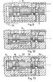
Sur les figures 5 , 8 , 11 , 14 , 17 , le fourreau 9 reste immobile , poussé à fond vers la gauche. Cela correspond au débit maximum , c'est-à-dire que le moteur que le moteur fontionne à pleine charge.In FIGS. 5, 8, 11, 14, 17, the
A la position de la figure 5 , la gorge 14 du tiroir 8 met en communication les canalisations 24 et 25: la face arrière de l'aiguille d'injecteur est donc en pres - sion, et il n'y a pas d'injection.At the position of FIG. 5, the
Pendant un premier cycle d'injection , le tiroir 8 commence à se déplacer vers la gauche (figure 8) à une vitesse sensiblement constante , quels que soient la charge et le régime du moteur. Au début du déplacement (figure 8) , le tiroir 8 vient obturer le perçage 21 , ce qui coupe la communication entre les canalisations 24 et 25. La gorge 13 arrive alors face au perçage 19 qu'elle démasque (figure 11) , ce qui relie la canalisation 24 de l'injecteur, à la canalisation de décharge 23 , à travers la gorge 12 et le perçage 16 qui sont alors en coïncidence : l'aiguille d' injecteur peut désormais se soulever de son siège , ce qui correspond au début de l'injection.During a first injection cycle, the
Pendant cotte première partie du déplacement du tiroir 8 , la canalisation 26 a toujours été reliée à la canalisation de décharge 23 par la gorge 12 et par le perça- ge 16 : le début d'injection est donc indépendant de la position du fourreau 9.During this first part of the movement of the
En poursuivant son déplacement vers la gauche , le tiroir 8 ( figure 14) vient fermer le perçage 16, si bien que l'injecteur se trouve désormais isolé de la décharge. Enfin , la gorge 11 arrive en face du perçage 15 (figure 17) , tandis que , entre temps , la gorge 14 est arrivée en face du perçage 20 , qui se trouve donc démasqué. Désormais , la canalisation 24 est à nouveau reliée à la haute pression de la canalisation 22 , par le perçage 15 , la gorge 11 , la canalisation 26 , la gorge 14 et le perçage 20. Cela correspond à l'instant de fin d'injection. D'après le fonctionnement qui vient d'être décrit , on voit que cet instant dépend uniquement de la position relative du fourreau 9 et du tiroir 8 , puisque la vitesse de ce dernier est constante . Autrement dit , le débit injecté ne dépend que de la position du fourreau 9. Ce débit reste constant tant que le fourreau 9 est immobile.By continuing to move to the left, the drawer 8 (Figure 14) closes the
On a représente sur les figures 4 , 7 , 10 , 13 , 16 , le déroulement du dycle d'injection lorsque le fourreau 9 occupe une position intermédiaire. Dans ce cas , du fait de la distance 29 dont le fourreau 9 est décalé vers la droite , le perçage 15 se trouve plus rapidement démasqué par la gorge 11 , avant que le tiroir 8 ne soit arrivé à fond de course vers la gauche des dessins. L'injection prend donc fin plus tôt, comme illustré sur la figure 13 : le débit de gazole injecté à chaque cycle se trouve dont réduit.There is shown in Figures 4, 7, 10, 13, 16, the course of the injection cycle when the
On a illustré sur les figures 3 , 6 , 9 , 12 , 15 , le fontionnement du dispositif lorsque le fourreau 9 est repoussé au maximum vers la droite , ce qui correspond à un décalage maximum 30 sensiblement égal à l'amplitude de la course du tiroir 8 . Dans ce cas , la canalisation 24 de l'injecteur n'est jamais reliée à la canalisation de décharge 23 . L'injecteur leste donc constamment à haute pression aux deux extrémités de l'aiguille : celle-ci n'est plus soumise qu'à la poussée de son ressort de tarage et elle reste fermée . Cela correspond à un débit injecté nul .Illustrated in Figures 3, 6, 9, 12, 15, the operation of the device when the
Tiroir et fourreau sont actionnés par 1' intermédiaire , soit d'une commande hydraulique , soit d'une commande électro-mécanique et , dans les deux cas , avec ou sans ressort de rappel . Les ordres d'ouverture d'injecteur et de durée d'injection sont sous la dépendance d'un calculateur dont les paramètres d'entrée représentent les conditions de fonctionnement et /ou les ordres reçus du conducteur , et dont les sorties sont définies à partir de ces entrées , au moyen d'un algorithme convenable assurant le fonctionnement du calculateur.Drawer and scabbard are actuated by 1 ' intermediate, either of a hydraulic control, or of an electro-mechanical control and, in both cases, with or without return spring. The injector opening and injection duration orders are dependent on a computer whose input parameters represent the operating conditions and / or the orders received from the driver, and whose outputs are defined from of these inputs, by means of a suitable algorithm ensuring the operation of the computer.
L'injection suivante peut se faire de façon analogue au cours du déplacement du tiroir de gauche à droite , auquel cas , dans la description qui précède , la position relative des pièces qui correspondait au début de la mise en communication de la décharge avec la face arrière de l'injecteur en devient la fin , et inversement.The next injection can be made in a similar way during the movement of the drawer from left to right, in which case, in the description above, the relative position of the parts which corresponded to the start of the connection of the discharge with the face rear of the injector becomes the end, and vice versa.
Mais l'injection suivante peut aussi se faire de façon rigoureusement identique à la précédente , si , entre deux injections , le tiroir reprend sa position initiale (à droite), correspondant au début de la première phase . Dans ce cas , il est nécessaire de prévoir .un dispositif supplémentaire , entre le dispositif qu'on vient de décrire et l'injecteur , de façon que , pendant la course retour du tiroir , la face arrière de l'aiguille reste constamment soumise à la haute pression. Ce dispositif supplémentaire pourrait être un distributeur jouant le rôle de robinet à trois voies reliant l'injecteur au dispositif objet de l'invention , pendant la phase injection et à une source haute pression entre deux phases d'injection , la communication étant commandée par le calculateur ou tout moyen approprié.However, the next injection can also be done strictly identical to the previous one, if, between two injections, the drawer returns to its initial position (on the right), corresponding to the start of the first phase. In this case, it is necessary to provide an additional device, between the device which has just been described and the injector, so that, during the return stroke of the slide, the rear face of the needle remains constantly subjected to high pressure. This additional device could be a distributor playing the role of a three-way valve connecting the injector to the device object of the invention, during the injection phase and to a high pressure source between two injection phases, the communication being controlled by the calculator or any suitable means.
On remarque que l'une des extrémités du tiroir (8),( gorges (11) et (12) ), coulisse à l'intérieur du fourreau (9) , lequel coulisse dans le corps (10) , alors que l'autre extrémité du tiroir (8) , ( gorges (13) et (14)), coulisse directement dans le corps (10').We note that one of the ends of the drawer (8) (grooves (11) and (12)) slides inside the sheath (9), which slides in the body (10), while the other end of the drawer (8), (grooves (13) and (14)), slides directly into the body (10 ').
Claims (9)
Applications Claiming Priority (2)
| Application Number | Priority Date | Filing Date | Title |
|---|---|---|---|
| FR8213138 | 1982-07-22 | ||
| FR8213138A FR2530734A1 (en) | 1982-07-22 | 1982-07-22 | DEVICE FOR THE ELECTRONIC INJECTION OF THE FUEL OF AN INTERNAL COMBUSTION ENGINE |
Publications (1)
| Publication Number | Publication Date |
|---|---|
| EP0102304A1 true EP0102304A1 (en) | 1984-03-07 |
Family
ID=9276380
Family Applications (1)
| Application Number | Title | Priority Date | Filing Date |
|---|---|---|---|
| EP83420130A Withdrawn EP0102304A1 (en) | 1982-07-22 | 1983-07-20 | Electronic fuel injection device for an internal-combustion engine |
Country Status (4)
| Country | Link |
|---|---|
| US (1) | US4604981A (en) |
| EP (1) | EP0102304A1 (en) |
| ES (1) | ES8403570A1 (en) |
| FR (1) | FR2530734A1 (en) |
Families Citing this family (5)
| Publication number | Priority date | Publication date | Assignee | Title |
|---|---|---|---|---|
| DE3614495A1 (en) * | 1986-04-29 | 1987-11-05 | Kloeckner Humboldt Deutz Ag | FUEL INJECTION DEVICE FOR AN INTERNAL COMBUSTION ENGINE |
| US5299919A (en) * | 1991-11-01 | 1994-04-05 | Paul Marius A | Fuel injector system |
| NL9402238A (en) * | 1994-12-29 | 1996-08-01 | Adrianus Martinus M Wildenberg | Fluid dosing device. |
| US6092546A (en) * | 1997-12-12 | 2000-07-25 | Alliedsignal Inc. | Fuel flow divider and pressurizing valve for gas turbine |
| DE10054202A1 (en) * | 2000-11-02 | 2002-05-29 | Siemens Ag | Injector for injecting fuel into a combustion chamber |
Citations (3)
| Publication number | Priority date | Publication date | Assignee | Title |
|---|---|---|---|---|
| DE2433309A1 (en) * | 1974-07-08 | 1976-01-29 | Sulzer Ag | Diesel engine injection control slide valve - has plunger end portion pressurised via throttle and servo discharge valve |
| US3983855A (en) * | 1973-07-12 | 1976-10-05 | C.A.V. Limited | Fuel injection system |
| FR2328853A1 (en) * | 1975-10-24 | 1977-05-20 | Karl Marx Stadt Automobilbau | Electromagnetic fuel injector for IC engine - has spring-controlled valve for biasing nozzle into closed position |
Family Cites Families (5)
| Publication number | Priority date | Publication date | Assignee | Title |
|---|---|---|---|---|
| US20254A (en) * | 1858-05-18 | Railroad-car for day and ntght service | ||
| US2827030A (en) * | 1955-11-22 | 1958-03-18 | Strumbos William | Fuel injection means for internal combustion engines |
| US3187733A (en) * | 1963-08-23 | 1965-06-08 | Int Harvester Co | Fuel injection system for internal combustion engines |
| GB1148905A (en) * | 1965-10-05 | 1969-04-16 | Cav Ltd | Improvements in or relating to fuel injection pumps |
| US3851635A (en) * | 1969-05-14 | 1974-12-03 | F Murtin | Electronically controlled fuel-supply system for compression-ignition engine |
-
1982
- 1982-07-22 FR FR8213138A patent/FR2530734A1/en active Granted
-
1983
- 1983-07-20 EP EP83420130A patent/EP0102304A1/en not_active Withdrawn
- 1983-07-20 US US06/516,114 patent/US4604981A/en not_active Expired - Fee Related
- 1983-07-21 ES ES524341A patent/ES8403570A1/en not_active Expired
Patent Citations (3)
| Publication number | Priority date | Publication date | Assignee | Title |
|---|---|---|---|---|
| US3983855A (en) * | 1973-07-12 | 1976-10-05 | C.A.V. Limited | Fuel injection system |
| DE2433309A1 (en) * | 1974-07-08 | 1976-01-29 | Sulzer Ag | Diesel engine injection control slide valve - has plunger end portion pressurised via throttle and servo discharge valve |
| FR2328853A1 (en) * | 1975-10-24 | 1977-05-20 | Karl Marx Stadt Automobilbau | Electromagnetic fuel injector for IC engine - has spring-controlled valve for biasing nozzle into closed position |
Also Published As
| Publication number | Publication date |
|---|---|
| FR2530734B1 (en) | 1984-12-14 |
| ES524341A0 (en) | 1984-04-16 |
| US4604981A (en) | 1986-08-12 |
| FR2530734A1 (en) | 1984-01-27 |
| ES8403570A1 (en) | 1984-04-16 |
Similar Documents
| Publication | Publication Date | Title |
|---|---|---|
| FR2593239A1 (en) | FUEL INJECTION SYSTEM FOR INTERNAL COMBUSTION ENGINE | |
| FR2520892A1 (en) | MOTOR SPEED REGULATOR SYSTEM | |
| CH644187A5 (en) | FUEL INJECTION DEVICE, PARTICULARLY FOR DIESEL ENGINES. | |
| FR2473633A1 (en) | FUEL INJECTION INSTALLATION FOR SELF-IGNITION INTERNAL COMBUSTION ENGINES | |
| EP0526616B1 (en) | Fuel injection device for internal combustion engines | |
| CA1112056A (en) | Method and device for improving the operation of a turbocompressor equipped motor | |
| FR2529260A1 (en) | FUEL INJECTION PUMP DISTRIBUTOR | |
| FR2720119A1 (en) | Injection system for an internal combustion engine. | |
| EP0102304A1 (en) | Electronic fuel injection device for an internal-combustion engine | |
| FR2497294A1 (en) | FUEL INJECTION SYSTEM | |
| EP0150138A2 (en) | Safety device for constant-pressure fuel-injection valve of an internal combustion engine | |
| EP0898649A1 (en) | Liquid fuel injecting device for internal combustion engine | |
| EP0500419A1 (en) | Proportional valve and control system with a plurality of actuators having each such a valve | |
| FR2883044A1 (en) | FUEL INJECTOR FOR INTERNAL COMBUSTION ENGINE | |
| FR2889259A3 (en) | Common fuel supply rail for motor vehicle, has piston housed in pressurized fuel receiving chamber and moved towards front or rear for varying volume of chamber in continuous and progressive manner to vary pressure in chamber | |
| FR2816665A1 (en) | INJECTOR WITH CASCADE AND FEED CONTROL DEVICE FROM A COMMON RAMP | |
| FR2508548A1 (en) | DEVICE FOR LIMITING THE FUEL INJECTION FLOW IN A DIESEL ENGINE | |
| FR2794496A1 (en) | CYLINDER SELECTOR FOR A HYDRAULIC MOTOR AVOIDING BRUTAL BRAKING WHEN CHANGING FROM SMALL CYLINDER TO LARGE CYLINDER | |
| FR2889260A3 (en) | Common fuelling rail for diesel engine of motor vehicle, has wall with conduit in fluid communication with chambers and modifying volume of one chamber under effect of fuel pressure in chamber, where chambers receive fuel under pressure | |
| EP0089301A1 (en) | Injection control system for diesel engines | |
| FR2608684A1 (en) | FUEL INJECTION PUMP FOR INTERNAL COMBUSTION ENGINE WITH CUT-OFF COUPLING ON THE DISCHARGE CHANNEL, DEPENDING ON THE LOAD | |
| EP0030907A1 (en) | Fuel injection device for an internal-combustion engine | |
| EP0056916B1 (en) | Device for fuel injection for an internal-combustion engine | |
| WO1998025026A1 (en) | Device for retarding the opening and reducing leaks for constant pressure injection systems used on diesel engines | |
| EP0560671A1 (en) | Distributor for pressurised fluid, especially lubricant in a central lubrication system |
Legal Events
| Date | Code | Title | Description |
|---|---|---|---|
| PUAI | Public reference made under article 153(3) epc to a published international application that has entered the european phase |
Free format text: ORIGINAL CODE: 0009012 |
|
| AK | Designated contracting states |
Designated state(s): AT BE CH DE FR GB IT LI LU NL SE |
|
| 17P | Request for examination filed |
Effective date: 19840207 |
|
| STAA | Information on the status of an ep patent application or granted ep patent |
Free format text: STATUS: THE APPLICATION HAS BEEN WITHDRAWN |
|
| 18W | Application withdrawn |
Withdrawal date: 19861122 |
|
| RIN1 | Information on inventor provided before grant (corrected) |
Inventor name: DAZZI, JEAN-LOUIS |