EP0102259A1 - Betätigungsvorrichtung für Gangschaltung - Google Patents
Betätigungsvorrichtung für Gangschaltung Download PDFInfo
- Publication number
- EP0102259A1 EP0102259A1 EP83401342A EP83401342A EP0102259A1 EP 0102259 A1 EP0102259 A1 EP 0102259A1 EP 83401342 A EP83401342 A EP 83401342A EP 83401342 A EP83401342 A EP 83401342A EP 0102259 A1 EP0102259 A1 EP 0102259A1
- Authority
- EP
- European Patent Office
- Prior art keywords
- derailleur
- actuating
- derailleurs
- actuating members
- members
- Prior art date
- Legal status (The legal status is an assumption and is not a legal conclusion. Google has not performed a legal analysis and makes no representation as to the accuracy of the status listed.)
- Granted
Links
Images


Classifications
-
- B—PERFORMING OPERATIONS; TRANSPORTING
- B62—LAND VEHICLES FOR TRAVELLING OTHERWISE THAN ON RAILS
- B62M—RIDER PROPULSION OF WHEELED VEHICLES OR SLEDGES; POWERED PROPULSION OF SLEDGES OR SINGLE-TRACK CYCLES; TRANSMISSIONS SPECIALLY ADAPTED FOR SUCH VEHICLES
- B62M25/00—Actuators for gearing speed-change mechanisms specially adapted for cycles
- B62M25/02—Actuators for gearing speed-change mechanisms specially adapted for cycles with mechanical transmitting systems, e.g. cables, levers
- B62M25/04—Actuators for gearing speed-change mechanisms specially adapted for cycles with mechanical transmitting systems, e.g. cables, levers hand actuated
Definitions
- the present invention relates to derailleurs for cycles and more particularly to the control devices of these derailleurs.
- the object of this invention is to remedy these drawbacks and to provide a device which makes it possible to simplify the operation of the derailleurs, on a cycle or similar vehicle, and which avoids unfavorable positions of the chain.
- a control device for two derailleurs, for cycle or the like comprising two actuating members each connected to one of the two derailleurs by a transmission member, characterized in that it comprises an operating member of one of the actuating members, connected to the other member actuation by a dead travel link mechanism.
- the actuating members can be conventionally two pieces comprising at their periphery a groove and on each of which is hung the end of a transmission cable whose other end is connected to the corresponding derailleur.
- the operating member is a lever which is integral with the actuating member or integrally formed therewith.
- a single operating member makes it possible to simultaneously control the two derailleurs and the dead travel link provided in the transmission makes it possible to shift the control of the bottom derailleur relative to the control of the freewheel derailleur.
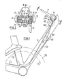
- Fig. 1 a part of a cycle frame C with respect to which have been arranged, very schematically, two bottom brackets P 1 , P 2 and a free wheel comprising six pinions R 1 , R 2 , R 3 , R 4 , R 5 , R 6 (Figs. 5 and 6).
- Two derailleur mechanisms which may be of conventional design and construction are provided for passing the chain from one pinion to another and from one chainring to the other, these two derailleur being actuated respectively by cables C 1 and C 2 .
- the drawing only shows the yoke A of the front derailleur, the rear derailleur not being shown.
- the actual control device is mounted on a support 10 which is itself fixed to the frame by any suitable means. It comprises a lever 11 integral in rotation with a bush 12 itself rotatably mounted on the support, the lever and the bush comprising flat areas ensuring their relative setting in rotation.
- the handle is held on the sleeve by means of a screw 13, with the interposition of at least one Belleville washer 14 between the screw and the handle and of a friction washer 15 between the handle and the support, while the sleeve includes a retaining flange 12a.
- the lever also comprises a portion of cylindrical surface 16 in which is formed a groove 17 defining a cam. One end of the cable C is guided in this groove is hung on the handle, the cable winding in the groove forming a cam as can be seen in FIG. 1. This cable is then guided by suitable means and its opposite end is connected to the freewheel derailleur.
- the second cable C 2 for actuating the bottom derailleur has one end fixed to a sleeve 21 which constitutes an actuating member and which has a groove 22 in its periphery similar to that of the lever 11.
- This sleeve is also made integral in rotation by means of flats or a square, of a socket 23 rotatably mounted on the support and retained relative to this support by means of a flange 23 .
- the sleeve is held on the sleeve by means of a screw 24, with the interposition of a Belleville washer 25 and a friction washer 26 between the sleeve and the support 10.
- the coupling means between the lever 11 and the sleeve 21, that is to say between the two cable actuating members C 1 , C 2 comprise, in the example chosen, lugs or dogs 18,27 extending to from the opposite ends of the two sockets 12 and 23.
- lugs or dogs 18,27 extending to from the opposite ends of the two sockets 12 and 23.
- the cable C 2 is wound on the sleeve 21 in a direction opposite to the direction of winding of the cable C 1 on the handle 11 and it passes over a deflection roller 28, as shown in FIG. 1.
- the effect of this arrangement is to reverse the direction of control of the bottom bracket derailleur, with respect to traditional arrangements, and thus to allow control of the two deraille by a single operating member.
- the roller has a cam surface 28 a and is connected to the sleeve by a drive mechanism consisting of two toothed sectors 29b engaged, respectively carried by the roller 28 and the sleeve 21 .
- This cam is intended to allow rapid passage from the small plate to the large plate.
- a relay device is also interposed on the cable C 2 .
- This cable is separated into two sections, a first section extending between the sleeve 21 and a plate 30 rotatably mounted on the frame around an axis parallel to the axis of articulation of the lever, and a second section s extending between this same plate and the front derailleur.
- the locations of the attachment points 31, 32 of the two sections of the cable C 2 on the plate are chosen so as to obtain a result which will be explained during the description of the operation of the device.
- Figs. 3 A to 3 D and Figs. 4A to 4. Illustrate the successive positions of the coupling means between the lever 11 and the sleeve 21 for a certain number of positions of this lever, respectively during movements of the large pinion towards the small pinion, as regards Figs. 3 A to 3 D and the reverse path as regards Figs. 4A to 4D.
- FIGs. 5 and 6 represent the positions of the chain between the sprockets and the chainrings, for a passage from the large sprocket to the small sprocket with regard to FIG. 5 and the reverse passage with regard to FIG. 6.
- Figs. as well as Figs. 7 and 8 will illustrate the operation of this device.
- the operating sequence is as follows: the lever 11 occupies the position shown at Fig. 1 and in FIG. 3A, By moving this lever clockwise, considering FIG. 1 over a certain angular travel for example of the order of 18 °, the cable is exerted on 5 sufficient traction to cause the chain to pass from the pinion R to the pinion R 2 .
- the sleeve 23 and the sleeve 2 1 are not driven taking into account the angular play a which exists between the pins 18 and 27.
- the change of chainring is preferably carried out when the pinion R goes to the pinion R 4 in the downward direction and when the pinion R 3 goes to the pinion R 2 in the direction amount, if we take a diagram similar to that of Figs. 5 and 6.
- two control handles are provided, one corresponding to the handle 11 of FIG. 1 and the other 41, integral with the sleeve 21 and corresponding to the usual lever for controlling the front derailleur.
- the socket 23 of FIG. 1 is made in two parts 42 and 43 in friction contact by their adjacent faces. Friction washers 45, 46 are provided between the lever 41 and the washer 25 as well as between this lever and the support 10. These different friction washers as well as the clamping screws 13, 24 allow brakes of different strength to be produced.
- the adjustment being made so that it is possible to use the lever 11 exactly under the conditions described in connection with the first embodiment, while allowing the user to also use the second lever 41 without thereby causing actuation of the lever 11 and act on the cable C 1 for controlling the rear derailleur.
- the friction force opposing the angular displacement of the assembly 11,12 is greater than the friction force between the sleeve element 43 and the support 10, while the friction connection between the two elements 42, 43 is greater than the braking of the lever 41 relative to the support 10.
- This embodiment therefore allows the user to retain additional freedom of choice in establishing the gear ratio by means of the front derailleur and the rear derailleur.
- the relay interposed on the cable C 2 can be replaced by a spring compensating device, which intervenes to absorb the traction exerted on the cable, while the front derailleur has reached its end of travel position determined by a positive stop.
- This compensating device can be incorporated in the cable itself or in the link to which this cable is connected and which acts on an articulated parallelogram or equivalent means to move the yoke of the front derailleur.
Applications Claiming Priority (2)
| Application Number | Priority Date | Filing Date | Title |
|---|---|---|---|
| FR8212800 | 1982-07-22 | ||
| FR8212800A FR2530573A1 (fr) | 1982-07-22 | 1982-07-22 | Dispositif de commande pour derailleurs |
Publications (2)
| Publication Number | Publication Date |
|---|---|
| EP0102259A1 true EP0102259A1 (de) | 1984-03-07 |
| EP0102259B1 EP0102259B1 (de) | 1987-01-21 |
Family
ID=9276202
Family Applications (1)
| Application Number | Title | Priority Date | Filing Date |
|---|---|---|---|
| EP19830401342 Expired EP0102259B1 (de) | 1982-07-22 | 1983-06-29 | Betätigungsvorrichtung für Gangschaltung |
Country Status (4)
| Country | Link |
|---|---|
| EP (1) | EP0102259B1 (de) |
| JP (1) | JPS5934044A (de) |
| DE (1) | DE3369292D1 (de) |
| FR (1) | FR2530573A1 (de) |
Cited By (4)
| Publication number | Priority date | Publication date | Assignee | Title |
|---|---|---|---|---|
| WO1992004549A1 (en) * | 1990-09-12 | 1992-03-19 | Norman Leslie Matthews | A fastener |
| DE4233820A1 (de) * | 1992-10-08 | 1993-04-29 | Christian Hannig | Vorrichtung zur verringerung von uebersetzungsunterschieden beim schaltvorgang mit einer kettenfahrradschaltung |
| FR2682926A1 (fr) * | 1991-10-24 | 1993-04-30 | Hetru Marcel | Selecteur de manóoeuvres pour leviers de commande de derailleur pour une transmission de cycles a trois plateaux. |
| US7849760B2 (en) | 2003-01-15 | 2010-12-14 | Etcetera | Speed changer with pre-determined gears, particularly for cycles |
Families Citing this family (4)
| Publication number | Priority date | Publication date | Assignee | Title |
|---|---|---|---|---|
| FR2660278A1 (fr) * | 1990-04-03 | 1991-10-04 | Socard Didier | Dispositif de gestion synchronisee de derailleurs de bicyclette. |
| ATE252482T1 (de) † | 1995-02-15 | 2003-11-15 | Shimano Kk | Verfahren zur festlegung der übersetzungsverhältnisse sowie entsprechende vorrichtung zum schalten einer fahrradkettenschaltung |
| JP4836722B2 (ja) * | 2006-09-12 | 2011-12-14 | 本田技研工業株式会社 | 自転車の多段変速機 |
| US8161841B2 (en) * | 2007-05-16 | 2012-04-24 | Shimano Inc. | Cable operating mechanism |
Citations (6)
| Publication number | Priority date | Publication date | Assignee | Title |
|---|---|---|---|---|
| US4055093A (en) * | 1976-06-18 | 1977-10-25 | Amf Incorporated | 10-Speed bicycles |
| DE2650011A1 (de) * | 1976-10-30 | 1978-05-03 | Hedrich Hans Eberhard Dipl Ing | Bedienungseinrichtung fuer fahrradgangschaltungen |
| FR2399355A1 (fr) * | 1977-08-02 | 1979-03-02 | Simplex Ets | Procede et moyens de montage et de commande des changements de vitesse a la roue arriere et au pedalier sur une bicyclette ou vehicule similaire |
| FR2424179A1 (fr) * | 1978-04-26 | 1979-11-23 | Rodriguez Cabeza Maximino | Mecanisme de changement de vitesses avec derailleur central pour bicyclette a commande par levier unique |
| US4279174A (en) * | 1979-02-02 | 1981-07-21 | Amf Incorporated | Single lever 10-speed bicycle shifter |
| EP0053776A2 (de) * | 1980-11-28 | 1982-06-16 | Maeda Industries, Ltd. | Doppelhebelanordnung für die Geschwindigkeitskontrolle eines Fahrrads |
Family Cites Families (3)
| Publication number | Priority date | Publication date | Assignee | Title |
|---|---|---|---|---|
| JPS5493100A (en) * | 1977-12-29 | 1979-07-23 | Shin Etsu Chem Co Ltd | Preparation of organopolysilazane high polymer |
| JPS5846891Y2 (ja) * | 1978-04-20 | 1983-10-26 | ヤンマー農機株式会社 | 農作業機における操作レバ−装置 |
| JPS5911787Y2 (ja) * | 1978-07-03 | 1984-04-10 | 株式会社クボタ | 農機の変速操作装置 |
-
1982
- 1982-07-22 FR FR8212800A patent/FR2530573A1/fr active Granted
-
1983
- 1983-06-29 EP EP19830401342 patent/EP0102259B1/de not_active Expired
- 1983-06-29 DE DE8383401342T patent/DE3369292D1/de not_active Expired
- 1983-07-20 JP JP58133542A patent/JPS5934044A/ja active Granted
Patent Citations (6)
| Publication number | Priority date | Publication date | Assignee | Title |
|---|---|---|---|---|
| US4055093A (en) * | 1976-06-18 | 1977-10-25 | Amf Incorporated | 10-Speed bicycles |
| DE2650011A1 (de) * | 1976-10-30 | 1978-05-03 | Hedrich Hans Eberhard Dipl Ing | Bedienungseinrichtung fuer fahrradgangschaltungen |
| FR2399355A1 (fr) * | 1977-08-02 | 1979-03-02 | Simplex Ets | Procede et moyens de montage et de commande des changements de vitesse a la roue arriere et au pedalier sur une bicyclette ou vehicule similaire |
| FR2424179A1 (fr) * | 1978-04-26 | 1979-11-23 | Rodriguez Cabeza Maximino | Mecanisme de changement de vitesses avec derailleur central pour bicyclette a commande par levier unique |
| US4279174A (en) * | 1979-02-02 | 1981-07-21 | Amf Incorporated | Single lever 10-speed bicycle shifter |
| EP0053776A2 (de) * | 1980-11-28 | 1982-06-16 | Maeda Industries, Ltd. | Doppelhebelanordnung für die Geschwindigkeitskontrolle eines Fahrrads |
Cited By (5)
| Publication number | Priority date | Publication date | Assignee | Title |
|---|---|---|---|---|
| WO1992004549A1 (en) * | 1990-09-12 | 1992-03-19 | Norman Leslie Matthews | A fastener |
| US5494368A (en) * | 1990-09-12 | 1996-02-27 | Matthews; Norman L. | Fastener |
| FR2682926A1 (fr) * | 1991-10-24 | 1993-04-30 | Hetru Marcel | Selecteur de manóoeuvres pour leviers de commande de derailleur pour une transmission de cycles a trois plateaux. |
| DE4233820A1 (de) * | 1992-10-08 | 1993-04-29 | Christian Hannig | Vorrichtung zur verringerung von uebersetzungsunterschieden beim schaltvorgang mit einer kettenfahrradschaltung |
| US7849760B2 (en) | 2003-01-15 | 2010-12-14 | Etcetera | Speed changer with pre-determined gears, particularly for cycles |
Also Published As
| Publication number | Publication date |
|---|---|
| JPH0211926B2 (de) | 1990-03-16 |
| EP0102259B1 (de) | 1987-01-21 |
| JPS5934044A (ja) | 1984-02-24 |
| FR2530573A1 (fr) | 1984-01-27 |
| DE3369292D1 (en) | 1987-02-26 |
| FR2530573B1 (de) | 1985-02-08 |
Similar Documents
| Publication | Publication Date | Title |
|---|---|---|
| EP0727348B1 (de) | Verfahren zur Festlegung der Übersetzungsverhältnisse sowie entsprechende Vorrichtung zum Schalten einer Fahrradkettenschaltung | |
| US8602929B2 (en) | Motion resisting apparatus for a bicycle derailleur | |
| FR2541225A1 (fr) | Derailleur pour une bicyclette | |
| WO2012156613A1 (fr) | Dispositif de changement de vitesse pour velo | |
| FR2556681A1 (fr) | Direction de vehicule automobile a commande assistee par un moteur electrique | |
| FR2502101A1 (fr) | Changement de vitesse au pedalier des cycles et vehicules similaires | |
| EP0102259B1 (de) | Betätigungsvorrichtung für Gangschaltung | |
| WO2004074080A2 (fr) | Dispositif de commande de changement de vitesse pour un velo et velo equipe d’un tel dispositif | |
| FR2657061A1 (fr) | Dispositif de transmission a engrenages pour bicyclette. | |
| FR2881199A1 (fr) | Transmission mecanique par chaine | |
| WO2005044656A1 (fr) | Ensemble de commande de changement de vitesse combine a une commande de freinage pour un velo | |
| US6293882B1 (en) | Operating force compensating apparatus for a bicycle transmission | |
| FR2572047A1 (fr) | Mecanisme de changement de vitesse pour bicyclette | |
| US6640938B2 (en) | Shift assist apparatus for a bicycle | |
| FR2776613A1 (fr) | Boite de vitesses a 8 ou 12 rapports regulierement etages et commandes par une seule manette, a installer sur une bicyclette ordinaire | |
| FR2750669A1 (fr) | Dispositif monocommande de manoeuvre synchronisee de deux derailleurs avant et arriere d'un velo | |
| FR2508408A1 (fr) | Mecanisme de transmission par chaine pour bicyclette | |
| FR2539376A1 (fr) | Derailleur avec boitier de positionnement separe | |
| FR2531923A1 (fr) | Mecanisme d'entrainement de bicyclette comportant un moyeu a frein a retropedalage et bicyclette comprenant un tel mecanisme | |
| FR2550753A1 (fr) | Mecanisme de changement de vitesse pour chaine de bicyclette | |
| FR2724903A1 (fr) | Boite de vitesse pour arbres alignes | |
| FR2721896A3 (fr) | Ensemble de transmission pour bicyclette | |
| WO1997006048A1 (fr) | Dispositif de compensation d'effort pour une commande a cable d'un derailleur, notamment pour un velo | |
| FR2766251A1 (fr) | Dispositif d'entrainement et de transmission | |
| FR2751608A1 (fr) | Dispositif de commande synchronisee des derailleurs avant et arriere d'un cycle |
Legal Events
| Date | Code | Title | Description |
|---|---|---|---|
| PUAI | Public reference made under article 153(3) epc to a published international application that has entered the european phase |
Free format text: ORIGINAL CODE: 0009012 |
|
| AK | Designated contracting states |
Designated state(s): BE DE GB IT LU NL |
|
| 17P | Request for examination filed |
Effective date: 19831231 |
|
| ITF | It: translation for a ep patent filed |
Owner name: GUZZI E RAVIZZA S.R.L. |
|
| GRAA | (expected) grant |
Free format text: ORIGINAL CODE: 0009210 |
|
| AK | Designated contracting states |
Kind code of ref document: B1 Designated state(s): BE DE GB IT LU NL |
|
| REF | Corresponds to: |
Ref document number: 3369292 Country of ref document: DE Date of ref document: 19870226 |
|
| PG25 | Lapsed in a contracting state [announced via postgrant information from national office to epo] |
Ref country code: LU Free format text: LAPSE BECAUSE OF NON-PAYMENT OF DUE FEES Effective date: 19870630 |
|
| PLBE | No opposition filed within time limit |
Free format text: ORIGINAL CODE: 0009261 |
|
| STAA | Information on the status of an ep patent application or granted ep patent |
Free format text: STATUS: NO OPPOSITION FILED WITHIN TIME LIMIT |
|
| 26N | No opposition filed | ||
| PGFP | Annual fee paid to national office [announced via postgrant information from national office to epo] |
Ref country code: LU Payment date: 19900530 Year of fee payment: 8 |
|
| PGFP | Annual fee paid to national office [announced via postgrant information from national office to epo] |
Ref country code: DE Payment date: 19900622 Year of fee payment: 8 |
|
| PGFP | Annual fee paid to national office [announced via postgrant information from national office to epo] |
Ref country code: GB Payment date: 19900625 Year of fee payment: 8 |
|
| ITTA | It: last paid annual fee | ||
| PGFP | Annual fee paid to national office [announced via postgrant information from national office to epo] |
Ref country code: NL Payment date: 19900630 Year of fee payment: 8 |
|
| PGFP | Annual fee paid to national office [announced via postgrant information from national office to epo] |
Ref country code: BE Payment date: 19900712 Year of fee payment: 8 |
|
| PG25 | Lapsed in a contracting state [announced via postgrant information from national office to epo] |
Ref country code: GB Effective date: 19910629 |
|
| PG25 | Lapsed in a contracting state [announced via postgrant information from national office to epo] |
Ref country code: BE Effective date: 19910630 |
|
| BERE | Be: lapsed |
Owner name: HURET ET SES FILS Effective date: 19910630 |
|
| PG25 | Lapsed in a contracting state [announced via postgrant information from national office to epo] |
Ref country code: NL Effective date: 19920101 |
|
| NLV4 | Nl: lapsed or anulled due to non-payment of the annual fee | ||
| GBPC | Gb: european patent ceased through non-payment of renewal fee | ||
| PG25 | Lapsed in a contracting state [announced via postgrant information from national office to epo] |
Ref country code: DE Effective date: 19920401 |