EP0101955A2 - Méthode et appareil pour la commande de parcours - Google Patents
Méthode et appareil pour la commande de parcours Download PDFInfo
- Publication number
- EP0101955A2 EP0101955A2 EP83107497A EP83107497A EP0101955A2 EP 0101955 A2 EP0101955 A2 EP 0101955A2 EP 83107497 A EP83107497 A EP 83107497A EP 83107497 A EP83107497 A EP 83107497A EP 0101955 A2 EP0101955 A2 EP 0101955A2
- Authority
- EP
- European Patent Office
- Prior art keywords
- path
- point
- order
- arms
- coordinate system
- Prior art date
- Legal status (The legal status is an assumption and is not a legal conclusion. Google has not performed a legal analysis and makes no representation as to the accuracy of the status listed.)
- Granted
Links
Images


Classifications
-
- G—PHYSICS
- G05—CONTROLLING; REGULATING
- G05B—CONTROL OR REGULATING SYSTEMS IN GENERAL; FUNCTIONAL ELEMENTS OF SUCH SYSTEMS; MONITORING OR TESTING ARRANGEMENTS FOR SUCH SYSTEMS OR ELEMENTS
- G05B19/00—Programme-control systems
- G05B19/02—Programme-control systems electric
- G05B19/42—Recording and playback systems, i.e. in which the programme is recorded from a cycle of operations, e.g. the cycle of operations being manually controlled, after which this record is played back on the same machine
- G05B19/425—Teaching successive positions by numerical control, i.e. commands being entered to control the positioning servo of the tool head or end effector
-
- G—PHYSICS
- G05—CONTROLLING; REGULATING
- G05B—CONTROL OR REGULATING SYSTEMS IN GENERAL; FUNCTIONAL ELEMENTS OF SUCH SYSTEMS; MONITORING OR TESTING ARRANGEMENTS FOR SUCH SYSTEMS OR ELEMENTS
- G05B19/00—Programme-control systems
- G05B19/02—Programme-control systems electric
- G05B19/18—Numerical control [NC], i.e. automatically operating machines, in particular machine tools, e.g. in a manufacturing environment, so as to execute positioning, movement or co-ordinated operations by means of programme data in numerical form
- G05B19/41—Numerical control [NC], i.e. automatically operating machines, in particular machine tools, e.g. in a manufacturing environment, so as to execute positioning, movement or co-ordinated operations by means of programme data in numerical form characterised by interpolation, e.g. the computation of intermediate points between programmed end points to define the path to be followed and the rate of travel along that path
-
- G—PHYSICS
- G05—CONTROLLING; REGULATING
- G05B—CONTROL OR REGULATING SYSTEMS IN GENERAL; FUNCTIONAL ELEMENTS OF SUCH SYSTEMS; MONITORING OR TESTING ARRANGEMENTS FOR SUCH SYSTEMS OR ELEMENTS
- G05B2219/00—Program-control systems
- G05B2219/30—Nc systems
- G05B2219/33—Director till display
- G05B2219/33263—Conversion, transformation of coordinates, cartesian or polar
-
- G—PHYSICS
- G05—CONTROLLING; REGULATING
- G05B—CONTROL OR REGULATING SYSTEMS IN GENERAL; FUNCTIONAL ELEMENTS OF SUCH SYSTEMS; MONITORING OR TESTING ARRANGEMENTS FOR SUCH SYSTEMS OR ELEMENTS
- G05B2219/00—Program-control systems
- G05B2219/30—Nc systems
- G05B2219/34—Director, elements to supervisory
- G05B2219/34319—Sequence as function of nc controlled axis position, axis zone
-
- G—PHYSICS
- G05—CONTROLLING; REGULATING
- G05B—CONTROL OR REGULATING SYSTEMS IN GENERAL; FUNCTIONAL ELEMENTS OF SUCH SYSTEMS; MONITORING OR TESTING ARRANGEMENTS FOR SUCH SYSTEMS OR ELEMENTS
- G05B2219/00—Program-control systems
- G05B2219/30—Nc systems
- G05B2219/35—Nc in input of data, input till input file format
- G05B2219/35543—Cartesian to polar and vice versa
-
- G—PHYSICS
- G05—CONTROLLING; REGULATING
- G05B—CONTROL OR REGULATING SYSTEMS IN GENERAL; FUNCTIONAL ELEMENTS OF SUCH SYSTEMS; MONITORING OR TESTING ARRANGEMENTS FOR SUCH SYSTEMS OR ELEMENTS
- G05B2219/00—Program-control systems
- G05B2219/30—Nc systems
- G05B2219/42—Servomotor, servo controller kind till VSS
- G05B2219/42207—Generate points between start and end position, linear interpolation
-
- G—PHYSICS
- G05—CONTROLLING; REGULATING
- G05B—CONTROL OR REGULATING SYSTEMS IN GENERAL; FUNCTIONAL ELEMENTS OF SUCH SYSTEMS; MONITORING OR TESTING ARRANGEMENTS FOR SUCH SYSTEMS OR ELEMENTS
- G05B2219/00—Program-control systems
- G05B2219/30—Nc systems
- G05B2219/45—Nc applications
- G05B2219/45135—Welding
Definitions
- the present invention relates to a path control method and apparatus whichare well-suited especially for application to articulated machine tools and industrial robots having path-controlled parts (parts whose paths are to be controlled) movable within three-dimensional regions.
- a path-controlled part is controlled in such a way that principal points concerning movement paths are stored as teach points in memory means in advance, and that an interpolation operation is performed by reading out the stored information.
- the interpolation operation becomes more complicated with increase in the number of movable axes included from a base to the path-controlled part.
- industrial robots are taken as an example, recently they have five movable axes as the general trend. Further, robots of 6-axis setup are coming into wide. use. Accordingly, the period of time required for the interpolation operation tends to lengthen more.
- Industrial robots and machine tools are often required to perform operations for various functions, besides the operations for the path control.
- the operations are executed by microcomputers in many cases.
- the microcomputers are inexpensive, but they do not have very high operating capabilities. In the controls of the industrial robots and machine tools, it is the actual situation that the capabilities are utilized substantially fully. On the other hand, however, it is requested to perform a preciser control by executing the interpolation operation finely and lessening the meandering of the moving path.
- An object of the present invention is to provide a path control method which can shorten interpolating time intervals without considerably increasing a period of time required for an interpolation operation, and to construct an apparatus therefor.
- main path points expressed by a general coordinate system are obtained from a teach point information signal (hereafter "teach point information"), and a command signal (hereafter “command") expressed by the reference coordinate system of a moving object is obtained from the main path point information.
- at least one order expressed by the reference coordinate system of the moving object is obtained between such commands.
- the command has heretofore been evaluated, and a long operating time is taken for the evaluation because a coordinate transformation must be done. Since, however, the order can be executed by the four fundamental rules of arithmetic, it can be evaluated in a time much shorter than the time for evaluating the order is added to the time for evaluating the command, the total becomes slightly longer than the latter time.
- a cycle for evaluating the command can also be made somewhat longer than in the prior art.
- the period of time required for the- operation of path interpolation can also be made equal to, or rather shorter than, that in the prior art.
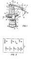
- numeral 1 designates a base, and numeral 2 a turntable. This turntable is turnable in a direction 9 indicated by arrows about a vertical axis 4 by drive means 3 which is disposed thereunder.
- a U-shaped holder 5 is fixed on the turntable 2.
- a first arm 6 is supported so as to be turnable in a direction cP about an axis 7.
- Shown at numeral 8 is a drive means for driving the first arm 6 in the direction ⁇ .
- a second arm 9 is pivotally mounted on the upper end of the first arm 6 through a pin 10.
- Disposed in parallel with the first arm 6 is a rear lever 11, one end of which is pivotally mounted on the second arm 9 through a pin 12 and the other end of which is pivotally mounted on one end of a lower lever, not shown, through a pin, not shown.
- the other end of the lower lever, not shown is driven on the axis 7 by drive means 13.
- the first arm 6, second arm 9, rear lever 11 and lower lever constitute a parallelogram link. Accordingly, when the drive means 13 is actuated, the second arm 9 is rotated in a direction & about the axis 14 of the pin 10.
- the pivotal points between the rear lever 11 and the lower lever, not shown, are provided with drive means 17 for rotating a wrist 15 in a direction. c 6 . about an axis 16 and drive means 19 for rotating the wrist 15 in a direction a about an axis 18.
- a welding torch 20 is attached to the wrist 15, and the intersection point 21 between the axis of this torch and the axis 18 is a path-controlled part (a part whose path is to be controlled).
- the moving object includes the five axes consisting of the axis of the turntable 2, the axis of the first arm 6, the axis of the second arm 9 and the two axes of the wrist 15.
- Encoders 22, 23, 24, 25 and 26 as position detecting means are respectively installed on the drive means 3, 8, 13, 17 and 19 so as to detect the rotational angles of the corresponding drive means.
- the mechanism of the articulated industrial robot shown in Figure 1 has been described, the characterizing features of the present invention do not reside in the mechanism. Accordingly, the mechanism is not restricted to that shown in Figure 1, but it may be any of the mechanisms of the Cartesian coordinate type, polar coordinate type, cylindrical coordinate type, etc.
- the member to be attached to the wrist 15 is not restricted to the welding torch, either.
- the mechanism illustrated in Figure 1 is described more in detail in U.S. Patent Application Serial No. 196,252, filed on October 10, 1980.
- FIG. 2 is a block diagram showing an example of a control device for controlling the mechanism shown in Figure 1. Now, reference is had to this diagram.
- Numeral 27 designates a console.
- This console 27 is shown -in front elevation in Figure 3, and has a switch 28 for supplying electric power to the whole robot, a switch 29 for changing- over a teaching mode and an automatic operation mode and an automatic operation mode and switches 30, 31, 32, 33, 34 and 35 required for teaching.
- the switches 30, 31 and 32 are three-position change-over switches for shifting the path-controlled part 21 in the directions of +X.-X, +Y.-Y and +Z.-Z, respectively;
- the switches 33 and 34 are three-position change-over switches for actuating the drive means 17 and 19 so as to move the wrist 15 in the directions of +a. -a and + ⁇ -- 0, respectively;
- the switch 35 is a switch which is thrown on a side Pe when only the posture of the moving object is changed without changing the position of the path-controlled part 21.
- Shown at numeral 36 in Figure 3 is a push button which is depressed when teach points are written into main storage means 37.
- the console 27 is connected to general control means 39 through a line 38.
- the general control means 39 generally controls the main storage means 37, temporary storage means 44, arithmetic means 45 and control means 46 through lines 40, 41, 42 and 43. In addition, the general control means 39 provides timing pulses.
- the main storage means 37 stores the teach points as stated before.
- the temporary storage means 44 temporarily stores commands through a line 47.
- the arithmetic means 45 evaluates a main path point on the basis of the information of the adjacent teach points inputted from the main storage means through a line 48, calculates commands for the respective drive means 3, 8, 13, 17 and 19 necessary for moving the path-controlled part 21 to this main path point, and processes the adjacent commands so as to operate an order for interpolating between these commands. Further, when any of the change-over switches 30, 31 and 32, for example, the switch 30 is thrown on the +X side, the arithmetic means 45 executes an operation necessary for moving the path-controlled part 21 in the +X direction.
- the control means 46 receives the commands and orders through a line 49 from the arithmetic means 45, and successively gives the differences between them and the outputs of the encoders 22 -26 to the corresponding drive means 3, 8, 13, 17 and 19 through a line 50.
- Shown at numeral 51 is a line which connects the encoders 22 - 26 with the control means 46.
- Equation (1) is an equation for evaluating the variations ⁇ l , ⁇ l and ⁇ l of e, ⁇ and ⁇ required for moving the path-controlled part 21 by ⁇ x , ⁇ y and ⁇ z
- a 11 -a 55 are coefficients which are determined by the construction of the mechanism shown in Figure 1.
- Equation (1) The operated results obtained with Equation (1) are sent to the control means 46 through the line 49.
- control means 46 Upon receiving these outputs and further the outputs of the encoders 22, 23 and 24, the control means 46 sends signals corresponding to their differences to the drive means 3, 8 and 13, so as to actuate these means.
- control means 46 Upon receiving these outputs and further the outputs of the encoders 22, 23, 24 and 25, the control means 46 supplies the drive means 3, 8, 13 and 17 with signals corresponding to their differences, so as to actuate these means.
- the push button 36 provided on the console 27 is depressed. Then, information on e, ⁇ , ⁇ , a and ⁇ which the arithmetic means 45 is delivering at that time are written into the main storage means 37. When the writing has ended, the push button 36 is released, whereupon similar operations are carried out for new teach points.
- Figure 4 shows the flow of the steps of the path control method of the present invention. It will be hereunder referred to, along with Figures 5 and 6, illustrative of teach points, etc.
- the general control means 39 feeds the outputs ( ⁇ O , ⁇ O , ⁇ O , ⁇ O , ⁇ O ) of the respective encoders 22, 23, 24, 25 and 26 into the arithmetic means 45 through a line 52 as indicated at 4b.
- the position of the path-controlled part 21 at this time is supposed T O .
- the arithmetic means performs a coordinate transformation by substituting ( ⁇ O , ⁇ O' ⁇ O , ⁇ O , ⁇ O ) into Equation (2), to operate the values x O , y O , and z O of the general coordinate system corresponding thereto: where A is a term composed of (a 11 -a 55 ) in Equation (1).
- the general control means 39 writes (X O , y O , z O ) into the temporary storage means 44.
- the general control means 39 reads out teach point information ( ⁇ 1 , ⁇ 1 , ⁇ 1 , ⁇ 1 , ⁇ 1 , ⁇ 1 ) on a first.
- teach point T 1 expressed by the construction of the moving object, from the main storage means 37 and inputs them to the arithmetic means 45.
- the arithmetic means 45 substitutes ( 8 1 , ⁇ 1 , ⁇ 1 , ⁇ 1 , ⁇ 1 ) into Equation (2), to operate the values ( x l , y l , z l ) of the general coordinate system.
- the general control means 39 reads out x o , y O and z O from the temporary storage means 44 and inputs them to the arithmetic means 45.
- the arithmetic means 45 calculates the distance L between the points T O and T 1 in accordance with Equation (3): Further, as indicated at 4i, the arithmetic means 45 evaluates according to Equation (4) the number N of timing pulses which will be needed for moving the path-controlled part 21 from T O to T 1 : where L denotes the distance between the adjacent main path points, and B denotes the number of orders per axis to be obtained between the adjacent main path points.
- the arithmetic means 45 evaluates the X-, Y- and Z-directional component distances ⁇ x a , ⁇ y a and ⁇ z a between the adjacent main path points P 1 , P 2 Vietnamese and P n , between the starting point T O and P 1 and between P n and the end point T 1 in accordance with (5) - (7):
- the arithmetic means 45 evaluates main path point commands X mn , Y mn and Z mn which are the values of the main path points P 1 , P 2 Vietnamese and P n on the general coordinate system, by substituting ⁇ x a , ⁇ y a and ⁇ z a into Equations (8), (9) and (10) : These operations are executed in synchronism with the timing pulses from the general control means 39.
- the arithmetic means 45 evaluates angles ⁇ a and ⁇ a to change between the adjacent main path points P 1 , P 2 7-8 and P n , between the starting point T 0 and P 1 and between P n and the end point T 1 by substituting ⁇ 0 ' ⁇ 0 , ⁇ 1 , ⁇ 1 and N into Equations (11) and (12):
- the arithmetic means 45 evaluat ⁇ mn and ⁇ mn on the angles a and ⁇ of the respective main path points P 10 , P 20 Vietnamese and P mO , expressed by the reference coordinate system of the moving object, by substituting ⁇ a and ⁇ a into Equations (13) and (14):
- the arithmetic means performs a coordinate transformation by substituting the values of ⁇ mn and ⁇ mn and those of X mn , Y and Z into Equation (15), to obtain commands ⁇ mn , ⁇ mn and ⁇ mn expressed by the reference coordinate system of the moving object. These operations are executed in synchronism with the timing pulses from the general control means 39.
- the values ⁇ X a , ⁇ Y a , ⁇ Z a , ⁇ a and ⁇ a may be also evaluated by using a velocity unit which is given as teaching information.
- Equations using the velocity unit v are as follows: [Storing Step]
- the commands ⁇ mn , ⁇ mn , ⁇ mn , a and ⁇ mn are stored into the temporary storage means 44.
- the commands stored in the temporary storage means 44 are read out so as to evaluate the magnitudes of the signals of the respective axes, ⁇ b , ⁇ b , ⁇ b , ⁇ b and ⁇ b to be changed in the sampling period, in accordance with Equations (16) - (20):
- Equations (21) - (25) are substituted into Equations (21) - (25) so as to evaluate orders ⁇ mq , ⁇ mq , ⁇ mq , ⁇ mq and ⁇ mq for the interpolation between the adjacent two sets of commands as expressed by the reference coordinate system of the moving object:
- the control means 46 evaluates the differences between the orders ⁇ mqn , ⁇ mqn , ⁇ mqn , ⁇ mqn and ⁇ mqn and positional information expressive of the positions of the respective drive means 2, 8, 13, 17 and 19, namely, the outputs of the encoders 22 - 26 as indicated at 4s, and affords them to the corresponding drive means 3-19 as indicated at 4t.
- control means 46 evaluates the differences between the commands ⁇ mn , ⁇ mn , ⁇ mn , ⁇ mn and ⁇ mn and the outputs of the encoders 22-26, and applies them to the corresponding drive means 3, 8, 13, 17 and 19.
- the general control means 39 reads out teach point information ⁇ n , ⁇ n , ⁇ n , a and ⁇ n expressive of teach points T 2 , across, T n-1 and T from the main storage means 37 in succession.
- the arithmetic means 45 evaluates main path points, commands and orders between the respective teach points, and applies them to the control means 46 in synchronism with the timing pulses.
- the control means 46 supplies the respective drive means 3, 8, 13, 17 and 19 with signals which correspond to the differences between the commands and orders and the outputs of the encoders.
- both the teach points T n and T n-1 can be obtained on the basis of the information stored in the main storage means.
- the teach point T n is evaluated from the stored information of the main storage means, while the other teach point T n-1 may be evaluated using the outputs of the encoders 22-26 at the time at which the path-controlled part 21 lies near the point T n-1 .
- the path-controlled part 21 need not always pass the teach points. As disclosed in U.S. Patent 3,661,051, when the path-controlled part has come very close to a teach point, the next teach point is read out from storage means, whereby the path-controlled part can be moved along a shorter path as illustrated by each two-dot chain line in Figure 5 by way of example.
- the main storage means 37 can also store the teach point information as the values X, Y and Z expressed by.the general coordinate system and the angular information a and ⁇ .
- the outputs of the respective positional detectors can be written instead of the signals delivered by the arithmetic means.
- commands are obtained by operations attended with coordinate transformations, while orders of easy operations attended with no coordinate transformations are obtained between the commands, and a moving object is driven on the basis of these commands and orders, so that a large number of path points can be evaluated without considerably lengthening an operating period of time. Accordingly, the path of a path-controlled object is stabilized.
Landscapes
- Engineering & Computer Science (AREA)
- Physics & Mathematics (AREA)
- General Physics & Mathematics (AREA)
- Automation & Control Theory (AREA)
- Computing Systems (AREA)
- Theoretical Computer Science (AREA)
- Human Computer Interaction (AREA)
- Manufacturing & Machinery (AREA)
- Robotics (AREA)
- Numerical Control (AREA)
Applications Claiming Priority (2)
| Application Number | Priority Date | Filing Date | Title |
|---|---|---|---|
| JP135172/82 | 1982-08-04 | ||
| JP57135172A JPS5927307A (ja) | 1982-08-04 | 1982-08-04 | 経路制御方法及び装置 |
Publications (3)
| Publication Number | Publication Date |
|---|---|
| EP0101955A2 true EP0101955A2 (fr) | 1984-03-07 |
| EP0101955A3 EP0101955A3 (en) | 1986-07-02 |
| EP0101955B1 EP0101955B1 (fr) | 1992-03-04 |
Family
ID=15145514
Family Applications (1)
| Application Number | Title | Priority Date | Filing Date |
|---|---|---|---|
| EP83107497A Expired - Lifetime EP0101955B1 (fr) | 1982-08-04 | 1983-07-29 | Méthode et appareil pour la commande de parcours |
Country Status (4)
| Country | Link |
|---|---|
| US (1) | US4541060A (fr) |
| EP (1) | EP0101955B1 (fr) |
| JP (1) | JPS5927307A (fr) |
| DE (1) | DE3382515D1 (fr) |
Cited By (2)
| Publication number | Priority date | Publication date | Assignee | Title |
|---|---|---|---|---|
| EP0335320A2 (fr) * | 1988-03-28 | 1989-10-04 | Tsudakoma Corporation | Méthode de commande centralisée pour métiers à tisser |
| USRE38702E1 (en) | 1992-02-11 | 2005-02-15 | Innovation 2 Market Limited | Security system |
Families Citing this family (28)
| Publication number | Priority date | Publication date | Assignee | Title |
|---|---|---|---|---|
| DE3375107D1 (en) * | 1982-10-29 | 1988-02-11 | Toshiba Kk | Control system of multi-joint arm robot apparatus |
| US5307447A (en) * | 1982-10-29 | 1994-04-26 | Kabushiki Kaisha Toshiba | Control system of multi-joint arm robot apparatus |
| JPS59114609A (ja) * | 1982-12-22 | 1984-07-02 | Hitachi Ltd | ロボットの制御装置 |
| JPS59218513A (ja) * | 1983-05-26 | 1984-12-08 | Fanuc Ltd | 工業用ロボツトの円弧制御法 |
| JPS6055414A (ja) * | 1983-09-05 | 1985-03-30 | Mitsubishi Electric Corp | 加工装置 |
| JPS60112111A (ja) * | 1983-11-24 | 1985-06-18 | Toyota Central Res & Dev Lab Inc | 無人車の誘導制御装置 |
| US4654805A (en) * | 1985-05-06 | 1987-03-31 | Autographic Business Forms, Inc. | Computer assisted design and electromechanical operating system |
| US4680519A (en) * | 1985-09-23 | 1987-07-14 | General Electric Co. | Recursive methods for world-to-joint transformation for a robot manipulator |
| JPH0724936B2 (ja) * | 1986-01-08 | 1995-03-22 | 株式会社日立製作所 | 自動溶接装置 |
| JPS62163109A (ja) * | 1986-01-14 | 1987-07-18 | Mitsubishi Electric Corp | 数値制御装置 |
| JPS63257807A (ja) * | 1987-04-15 | 1988-10-25 | Fanuc Ltd | ロボツト制御装置 |
| JP2512099B2 (ja) * | 1988-08-24 | 1996-07-03 | 松下電器産業株式会社 | ロボットの動作教示方法および制御装置 |
| JPH02113305A (ja) * | 1988-10-24 | 1990-04-25 | Fanuc Ltd | スプライン補間方法 |
| JPH02161503A (ja) * | 1988-12-14 | 1990-06-21 | Mitsubishi Heavy Ind Ltd | ロボットにおける教示位置データの修正・再生方法 |
| US5204942A (en) * | 1989-01-10 | 1993-04-20 | Kabushiki Kaisha Kobe Seiko Sho | Robot control system for controlling a set of industrial robots for cooperative operation |
| SE461383B (sv) * | 1989-01-11 | 1990-02-12 | Inst Mash Im A Ablagonravova A | Foerfarande foer styrning av en s k mekanisk resonanshand |
| JP2786225B2 (ja) * | 1989-02-01 | 1998-08-13 | 株式会社日立製作所 | 工業用ロボットの制御方法及び装置 |
| DE58909509D1 (de) * | 1989-02-28 | 1996-01-04 | Siemens Ag | Steuerungsverfahren bei einer numerischen Werkzeugmaschine oder einem Roboter. |
| US5055755A (en) * | 1989-05-31 | 1991-10-08 | Kabushiki Kaisha Toshiba | Distribution control apparatus |
| JPH04111006A (ja) * | 1990-08-30 | 1992-04-13 | Kobe Steel Ltd | ロボットの経路補間方法 |
| JP2716270B2 (ja) * | 1990-12-27 | 1998-02-18 | 株式会社日立製作所 | マニピュレ−タ |
| JPH0743296B2 (ja) * | 1991-01-16 | 1995-05-15 | 株式会社堀場製作所 | 自動車自動運転ロボットの制御方法 |
| JP3665353B2 (ja) * | 1993-09-14 | 2005-06-29 | ファナック株式会社 | ロボットの教示位置データの3次元位置補正量取得方法及びロボットシステム |
| DE10224755A1 (de) * | 2002-06-04 | 2003-12-24 | Siemens Ag | Steuerungsverfahren für eine industrielle Bearbeitungsmaschine |
| WO2004108365A1 (fr) * | 2003-06-02 | 2004-12-16 | Honda Motor Co., Ltd. | Procede de preparation de donnees d'apprentissage pour robot articule |
| US20070142966A1 (en) * | 2005-12-20 | 2007-06-21 | Khalid Mirza | Process for moving a robot |
| FR2918477A1 (fr) * | 2007-07-04 | 2009-01-09 | Aldebaran Robotics Soc Par Act | Procede d'edition de mouvements d'un robot |
| JP2009166076A (ja) * | 2008-01-15 | 2009-07-30 | Kobe Steel Ltd | 溶接ロボット |
Citations (5)
| Publication number | Priority date | Publication date | Assignee | Title |
|---|---|---|---|---|
| GB2021287A (en) * | 1978-04-26 | 1979-11-28 | Fujitsu Fanuc Ltd | Industrial robot control apparatus |
| EP0042202A2 (fr) * | 1980-05-23 | 1981-12-23 | Shin Meiwa Industry Co., Ltd. | Commande automatique de position |
| EP0060563A1 (fr) * | 1981-03-18 | 1982-09-22 | Kabushiki Kaisha Yaskawa Denki Seisakusho | Dispositif de commande d'interpolation pour robot articulé industriel |
| EP0075792A2 (fr) * | 1981-09-24 | 1983-04-06 | Hitachi, Ltd. | Système de commande pour la main d'un robot |
| EP0076498A2 (fr) * | 1981-10-07 | 1983-04-13 | Messer Griesheim Gmbh | Procédé de contrôle d'un chalumeau électrique d'un robot de soudage |
Family Cites Families (6)
| Publication number | Priority date | Publication date | Assignee | Title |
|---|---|---|---|---|
| US30132A (en) * | 1860-09-25 | Improvement in hay-rakes | ||
| US3661051A (en) * | 1969-03-18 | 1972-05-09 | Unimation Inc | Programmed manipulator apparatus |
| US3920972A (en) * | 1974-07-16 | 1975-11-18 | Cincinnati Milacron Inc | Method and apparatus for programming a computer operated robot arm |
| JPS55118107A (en) * | 1979-03-05 | 1980-09-10 | Hitachi Ltd | Method and device for control of automatic working device |
| JPS57139810A (en) * | 1981-02-20 | 1982-08-30 | Shin Meiwa Ind Co Ltd | Controlling method of industrial robot and its device |
| US4456961A (en) * | 1982-03-05 | 1984-06-26 | Texas Instruments Incorporated | Apparatus for teaching and transforming noncoincident coordinate systems |
-
1982
- 1982-08-04 JP JP57135172A patent/JPS5927307A/ja active Granted
-
1983
- 1983-07-26 US US06/517,288 patent/US4541060A/en not_active Expired - Lifetime
- 1983-07-29 EP EP83107497A patent/EP0101955B1/fr not_active Expired - Lifetime
- 1983-07-29 DE DE8383107497T patent/DE3382515D1/de not_active Expired - Lifetime
Patent Citations (5)
| Publication number | Priority date | Publication date | Assignee | Title |
|---|---|---|---|---|
| GB2021287A (en) * | 1978-04-26 | 1979-11-28 | Fujitsu Fanuc Ltd | Industrial robot control apparatus |
| EP0042202A2 (fr) * | 1980-05-23 | 1981-12-23 | Shin Meiwa Industry Co., Ltd. | Commande automatique de position |
| EP0060563A1 (fr) * | 1981-03-18 | 1982-09-22 | Kabushiki Kaisha Yaskawa Denki Seisakusho | Dispositif de commande d'interpolation pour robot articulé industriel |
| EP0075792A2 (fr) * | 1981-09-24 | 1983-04-06 | Hitachi, Ltd. | Système de commande pour la main d'un robot |
| EP0076498A2 (fr) * | 1981-10-07 | 1983-04-13 | Messer Griesheim Gmbh | Procédé de contrôle d'un chalumeau électrique d'un robot de soudage |
Cited By (3)
| Publication number | Priority date | Publication date | Assignee | Title |
|---|---|---|---|---|
| EP0335320A2 (fr) * | 1988-03-28 | 1989-10-04 | Tsudakoma Corporation | Méthode de commande centralisée pour métiers à tisser |
| EP0335320A3 (fr) * | 1988-03-28 | 1992-09-02 | Tsudakoma Corporation | Méthode de commande centralisée pour métiers à tisser |
| USRE38702E1 (en) | 1992-02-11 | 2005-02-15 | Innovation 2 Market Limited | Security system |
Also Published As
| Publication number | Publication date |
|---|---|
| JPS5927307A (ja) | 1984-02-13 |
| US4541060A (en) | 1985-09-10 |
| EP0101955B1 (fr) | 1992-03-04 |
| JPH035606B2 (fr) | 1991-01-28 |
| DE3382515D1 (de) | 1992-04-09 |
| EP0101955A3 (en) | 1986-07-02 |
Similar Documents
| Publication | Publication Date | Title |
|---|---|---|
| EP0101955A2 (fr) | Méthode et appareil pour la commande de parcours | |
| US4517653A (en) | Method for controlling an industrial robot | |
| US6124693A (en) | Robot controller | |
| US4706204A (en) | Controller for movable robot for moving a work element through a continuous path | |
| EP0114362A1 (fr) | Procédé et système pour commander des robots industriels | |
| EP0383944B1 (fr) | Procede d'apprentissage et appareil de commande pour un robot | |
| EP0076498B1 (fr) | Procédé de contrôle d'un chalumeau électrique d'un robot de soudage | |
| JPS6051121B2 (ja) | ロボツトア−ム用のプログラムを発生する方法 | |
| US4967125A (en) | Tool posture control method for a robot | |
| JPS5871087A (ja) | ロボツトア−ムを非プログラム径路に沿って自動的に動かす装置 | |
| US5003237A (en) | Method of correcting and playing back positional instruction data in a robot | |
| US4523287A (en) | Method for extrapolating a path of a robot and apparatus therefor | |
| US4912383A (en) | Method of controlling a robot | |
| US4970370A (en) | Track control method for a robot | |
| JPS62251901A (ja) | 多軸ロボツトの経路制御装置 | |
| JPH07200030A (ja) | ロボット動作計画装置、コントローラ、および、最適軌道生成方法 | |
| JPS59229614A (ja) | ロボツト制御装置 | |
| JPS60195616A (ja) | 産業用ロボツト | |
| JP3767643B2 (ja) | 教示用力センサ | |
| JP2577003B2 (ja) | ロボットの制御方法 | |
| JPS5810197B2 (ja) | エンカツソウジユウソウチ | |
| JP3644551B2 (ja) | ロボットの制御方法 | |
| KR100321497B1 (ko) | 로봇의 운동지시 방법 | |
| JPS61193206A (ja) | ロボツトの教示方法 | |
| JPS60220408A (ja) | 関節形ロボツト用制御装置 |
Legal Events
| Date | Code | Title | Description |
|---|---|---|---|
| PUAI | Public reference made under article 153(3) epc to a published international application that has entered the european phase |
Free format text: ORIGINAL CODE: 0009012 |
|
| 17P | Request for examination filed |
Effective date: 19830803 |
|
| AK | Designated contracting states |
Designated state(s): DE FR GB |
|
| PUAL | Search report despatched |
Free format text: ORIGINAL CODE: 0009013 |
|
| AK | Designated contracting states |
Kind code of ref document: A3 Designated state(s): DE FR GB |
|
| 17Q | First examination report despatched |
Effective date: 19880826 |
|
| GRAA | (expected) grant |
Free format text: ORIGINAL CODE: 0009210 |
|
| AK | Designated contracting states |
Kind code of ref document: B1 Designated state(s): DE FR GB |
|
| REF | Corresponds to: |
Ref document number: 3382515 Country of ref document: DE Date of ref document: 19920409 |
|
| ET | Fr: translation filed | ||
| PG25 | Lapsed in a contracting state [announced via postgrant information from national office to epo] |
Ref country code: GB Effective date: 19920729 |
|
| PLBE | No opposition filed within time limit |
Free format text: ORIGINAL CODE: 0009261 |
|
| STAA | Information on the status of an ep patent application or granted ep patent |
Free format text: STATUS: NO OPPOSITION FILED WITHIN TIME LIMIT |
|
| 26N | No opposition filed | ||
| GBPC | Gb: european patent ceased through non-payment of renewal fee |
Effective date: 19920729 |
|
| PGFP | Annual fee paid to national office [announced via postgrant information from national office to epo] |
Ref country code: FR Payment date: 20020716 Year of fee payment: 20 |
|
| PGFP | Annual fee paid to national office [announced via postgrant information from national office to epo] |
Ref country code: DE Payment date: 20020927 Year of fee payment: 20 |