EP0101552B1 - Magnetic materials, permanent magnets and methods of making those - Google Patents
Magnetic materials, permanent magnets and methods of making those Download PDFInfo
- Publication number
- EP0101552B1 EP0101552B1 EP83106573A EP83106573A EP0101552B1 EP 0101552 B1 EP0101552 B1 EP 0101552B1 EP 83106573 A EP83106573 A EP 83106573A EP 83106573 A EP83106573 A EP 83106573A EP 0101552 B1 EP0101552 B1 EP 0101552B1
- Authority
- EP
- European Patent Office
- Prior art keywords
- permanent magnet
- rare earth
- grain size
- sintered
- crystal grain
- Prior art date
- Legal status (The legal status is an assumption and is not a legal conclusion. Google has not performed a legal analysis and makes no representation as to the accuracy of the status listed.)
- Expired
Links
- 0 C1CC*CC1 Chemical compound C1CC*CC1 0.000 description 5
Images


Classifications
-
- H—ELECTRICITY
- H01—ELECTRIC ELEMENTS
- H01F—MAGNETS; INDUCTANCES; TRANSFORMERS; SELECTION OF MATERIALS FOR THEIR MAGNETIC PROPERTIES
- H01F1/00—Magnets or magnetic bodies characterised by the magnetic materials therefor; Selection of materials for their magnetic properties
- H01F1/01—Magnets or magnetic bodies characterised by the magnetic materials therefor; Selection of materials for their magnetic properties of inorganic materials
- H01F1/03—Magnets or magnetic bodies characterised by the magnetic materials therefor; Selection of materials for their magnetic properties of inorganic materials characterised by their coercivity
- H01F1/032—Magnets or magnetic bodies characterised by the magnetic materials therefor; Selection of materials for their magnetic properties of inorganic materials characterised by their coercivity of hard-magnetic materials
- H01F1/04—Magnets or magnetic bodies characterised by the magnetic materials therefor; Selection of materials for their magnetic properties of inorganic materials characterised by their coercivity of hard-magnetic materials metals or alloys
- H01F1/047—Alloys characterised by their composition
- H01F1/053—Alloys characterised by their composition containing rare earth metals
- H01F1/055—Alloys characterised by their composition containing rare earth metals and magnetic transition metals, e.g. SmCo5
- H01F1/057—Alloys characterised by their composition containing rare earth metals and magnetic transition metals, e.g. SmCo5 and IIIa elements, e.g. Nd2Fe14B
- H01F1/0571—Alloys characterised by their composition containing rare earth metals and magnetic transition metals, e.g. SmCo5 and IIIa elements, e.g. Nd2Fe14B in the form of particles, e.g. rapid quenched powders or ribbon flakes
- H01F1/0575—Alloys characterised by their composition containing rare earth metals and magnetic transition metals, e.g. SmCo5 and IIIa elements, e.g. Nd2Fe14B in the form of particles, e.g. rapid quenched powders or ribbon flakes pressed, sintered or bonded together
- H01F1/0577—Alloys characterised by their composition containing rare earth metals and magnetic transition metals, e.g. SmCo5 and IIIa elements, e.g. Nd2Fe14B in the form of particles, e.g. rapid quenched powders or ribbon flakes pressed, sintered or bonded together sintered
-
- H—ELECTRICITY
- H01—ELECTRIC ELEMENTS
- H01F—MAGNETS; INDUCTANCES; TRANSFORMERS; SELECTION OF MATERIALS FOR THEIR MAGNETIC PROPERTIES
- H01F1/00—Magnets or magnetic bodies characterised by the magnetic materials therefor; Selection of materials for their magnetic properties
- H01F1/01—Magnets or magnetic bodies characterised by the magnetic materials therefor; Selection of materials for their magnetic properties of inorganic materials
- H01F1/03—Magnets or magnetic bodies characterised by the magnetic materials therefor; Selection of materials for their magnetic properties of inorganic materials characterised by their coercivity
- H01F1/032—Magnets or magnetic bodies characterised by the magnetic materials therefor; Selection of materials for their magnetic properties of inorganic materials characterised by their coercivity of hard-magnetic materials
- H01F1/04—Magnets or magnetic bodies characterised by the magnetic materials therefor; Selection of materials for their magnetic properties of inorganic materials characterised by their coercivity of hard-magnetic materials metals or alloys
- H01F1/047—Alloys characterised by their composition
- H01F1/053—Alloys characterised by their composition containing rare earth metals
- H01F1/055—Alloys characterised by their composition containing rare earth metals and magnetic transition metals, e.g. SmCo5
- H01F1/057—Alloys characterised by their composition containing rare earth metals and magnetic transition metals, e.g. SmCo5 and IIIa elements, e.g. Nd2Fe14B
Definitions
- the present invention relates to novel magnetic materials and permanent magnets based on rare earth elements and iron without recourse to cobalt which is relatively rare and expensive.
- R denotes rare earth elements inclusive yttrium.
- Magnetic materials and permanent magnets are one of the important electric and electronic materials applied in an extensive range from various electrical appliances for domestic use to peripheral terminal devices of large-scaled computers. In view of recent needs for miniaturization and high efficiency of electric and electronic equipment, there has been an increasing demand for upgrading of permanent magnets and in general magnetic materials.
- typical permanent magnet materials currently in use are alnico, hard ferrite and rare earth-cobalt magnets.
- alnico magnets containing 20-30 wt % of cobalt.
- inexpensive hard'ferrite containing iron oxides as the main component has showed up as major magnet materials.
- Rare earth-cobalt magnets are very expensive, since they contain 50-65 wt % of cobalt and make use of Sm that is not much found in rare earth ores.
- such magnets have often been used primarily for miniaturized magnetic circuits of high added value, becuase they are by much superior to other magnets in magnetic properties.
- the rare earth magnets could be used abundantly and with less expense in a wider range.
- R-Fe 2 base compounds wherein R is at least one of the rare earth metals, have been investigated.
- the non-prepublished EP-A-108474 describes permanent magnetic materials with substantially elevated Curie temperature derived by spinning or quenching a melt of FE, B and R having a substantially "amorphous to finely crystalline structure", which term refers to solids having X-ray diffraction patterns which do not indicate the presence of fully crystalline phases.
- melt-quenched ribbons or sputtered thin films derived by the prior art are not any practical permanent magnets (bodies) that can be used as such. It would be practically impossible to obtain practical permanent magnets from these ribbons or thin films.
- rare earth cobalt magnets which result from compacting a powder of an intermetallic compound comprising 32-42 weight % of rare earth elements and 58-68 weight % of the sum of Co, Fe and Ni, to which at least one of Ta, V, B, Mn, Cr, Zr, Ti and Nb is added in an amount of no more than 2.0 weight %, and sintering the resultant compact. All of these compounds contain Co.
- An essential object of the present invention is to provide novel Co-free magnetic materials and permanent magnets.
- Another object of the present invention is to provide practical permanent magnets from which the aforesaid disadvantages are removed.
- a further object of the present invention is to provide magnetic materials and permanent magnets showing good magnetic properties at room temperature.
- a still further object of the present invention is to provide permanent magnets capable of achieving such high magnetic properties that could not be achieved by R-Co permanent magnets.
- a still further object of the present invention is to provide magnetic materials and permanent magnets which can be formed into any desired shape and size.
- a still further object of the present invention is to provide permanent magnets having magnetic anisotropy, good magnetic properties and excellent mechanical strength.
- a still further object of the present invention is to provide magnetic materials and permanent magnets obtained by making effective use of light rare earth elements occurring abundantly in nature.
- the present invention provides an alloy comprising Fe-B-R characterized by containing at least one stable compound of the ternary Fe-B-R type, which compound can be magnetized to become a permanent magnet at room temperature and above, wherein R stands for at least one rare earth element including yttrium.
- the present invention further provides a process for preparing such alloys according to claim 13 and use of these alloys according to claim 17. Besides this, the invention provides a permanent magnet material according to claim 18 and a process of making same according to claim 30. Furthermore, the invention provides a magnetic material according to claim 36 comprising at least 50 vol.
- % of a phase comprising at least one Fe-B-R type compound having a tetragonal structure, wherein R is at least one rare earth element including Y, a sintered magnetic material of a special composition according to claim 48, and a process of making a magnetic material powder showing a tetragonal structure according to claim 49 as well as permanent magnets according to claims 51 and 55, sintered permanent magnets according to claim 68 and a process for preparing same according to claim 87.
- novel magnetic materials and permanent magnets according to the present invention are essentially comprised of alloys essentially formed of novel intermetallic compounds and are substantially crystalline, said intermetallic compounds being at least characterized by their novel Curie points Tc.
- a magnetic material which comprises as indispensable components Fe, B and R (at least one of rare earth elements inclusive of Y), and in which a major phase is formed of an intermetallic compound(s) of the Fe-B-R type having a crystal structure of the substantially tetragonal system.
- a sintered magnetic material having a major phase formed of an intermetallic compound(s) consisting essentially of, by atomic percent, 8-30% R (at least one of rare earth elements inclusive of Y), 2-28% B and the balance being Fe with impurities.
- a sintered magnetic material having the same composition as the second embodiment, and having a major phase formed of an intermetallic compound(s) of the substantially tetragonal system.
- a sintered anisotropic permanent magnet consisting essentially of, by atomic percent, 8-30% R (at least one of rare earth elements inclusive of Y), 2-28% B and the balance being Fe with impurities.
- the fifth embodiment thereof provides a sintered anisotropic permanent magnet having a major phase formed of an intermetallic compound(s) of the Fe-B-R type having a crystal structure of the substantially tetragonal system, and consisting essentially of, by atomic percent 8-30% R (at least one of rare earth elements inclusive of Y), 2-28% B and the balance being Fe with impurities.
- % denotes atomic % in the present disclosure if not otherwise specified.
- the magnetic materials of the 1st to 3rd embodiments according to the present invention may contain as additional components at least one of elements M selected from the group given below in the amounts of no more than the values specified below, provided that the sum of M is no more than the maximum value among the values specified below of said elements M actually added and the amount of M is more than zero: These constitute the 6th-8th embodiments (Fe-B-R-M type) of the present invention, respectively.
- the permanent magnets (the 4th and 5th embodiments) of the present invention may further contain at least one of said additional elements M selected from the group given hereinabove in the amounts of no more than the values specified hereinabove, provided that the amount of M is not zero and the sum of M is no more than the maximum value among the values specified above of said elements M actually added.
- These embodiments constitute the 9th and 10th embodiments (Fe-B-R-M type) of the present invention.
- inventive permanent magnets can exhibit good magnet properties by containing 1 vol % or higher of nonmagnetic intermetallic compound phases.
- inventive magnetic materials are advantageous in that they can be obtained in the form of at least as-cast alloys, or powdery or granular alloys or a sintered mass, and applied to magnetic recording media (such as magnetic recording tapes) as well as magnetic paints, temperature-sensitive materials and the like. Besides the inventive magnetic materials are useful as the intermediaries for the production of permanent magnets.
- R-Fe base compounds provide Co-free permanent magnet materials showing large magnetic anisotropies and magnetic moments.
- R-Fe base compounds containing as R light rare earth elements have extremely low Curie temperatures, and cannot occur in a stable state.
- PrFe 2 is unstable and difficulty is involved in the preparation thereof since a large amount of Pr is required.
- studies have been made with a view to preparing novel compounds which are stable at room or elevated temperatures and have high Curie points on the basis of R and Fe.
- the Fe-B-R base alloys have been found to have a high crystal magnetic anisotropy constant Ku and an anisotropy field Ha standing comparison with that of the conventional SmCo type magnet.
- the permanent magnets according to the present invention are prepared by a so-called powder metallurgical process, i.e., sintering, and can be formed into any desired shape and size, as already mentioned.
- desired practical permanent magnets were not obtained by such a melt-quenching process as applied in the preparation of amorphous thin film alloys, resulting in no practical coercive force at all.
- the sintered bodies can be used in the as-sintered state as useful permanent magnets, and may of course be subjected to aging usually applied to conventional magnets.
- the permanent magnets according to the present invention are based on the Fe-B-R system, they need not contain Co.
- the starting materials are not expensive, since it is possible to use as R light rare earth elements that occur abundantly in view of the natural resource, whereas it is not necessarily required to use Sm or to use Sm as the main component. In this respect, the invented magnets are prominently useful.
- magnetic substances having high anisotropy field Ha potentially provide fine particle type magnets with high-performance as is the case with the hard ferrite or SmCo base magnets.
- sintered, fine particle type magnets were prepared with wide ranges of composition and varied crystal grain size after sintering to determine the permanent magnet properties thereof.
- the obtained magnet properties correlate closely with the mean crystal grain size after sintering.
- fine particle type magnets have magnetic walls which are formed within each of the particles, if the particles are large. For this reason, inversion of magnetization easily takes place due to shifting of the magnetic walls, resulting in a low Hc.
- the particles are reduced in size to below a certain value, no magnetic walls are formed within the particles. For this reason, the inversion of magnetization proceeds only by rotation, resulting in high Hc.
- the critical size defining the single magnetic domain varies depending upon diverse materials, and has been thought to be about 0.01 um for iron, about 1 11m for hard ferrite, and about 4 11m for SmCo.
- Hc of various materials increases around their critical size.
- Hc of 1 kOe or higher is obtained when the mean crystal grain size ranges from 1 to 80 pm, while Hc of 4 kOe or higher is obtained in a range of 2 to 40 ⁇ m.
- the permanent magnets according to the present invention are obtained as a sintered body, which enables production with any desired shape and size.
- the crystal grain size of the sintered body after sintering is of the primary concern. It has experimentally been ascertained that, in order to allow the Hc of the sintered compact to exceed 1 kOe, the mean crystal grain size should be no less than about 1 pm, preferably 1.5 11m, after sintering. In order to obtain sintered bodies having a smaller crystal grain size than this, still finer powders should be prepared prior to sintering.
- the Hc of the sintered bodies decrease considerably, since the fine powders of the Fe-B-R alloys are susceptible to oxidation, the influence of distortion applied upon the fine particles increases, superparamagnetic substances rather than ferromagnetic substances are obtained when the grain size is excessively reduced, or the like.
- the crystal grain size exceeds 80 ⁇ m, the obtained particles are not single magnetic domain particles, and include magnetic walls therein, so that the inversion of magnetization easily takes place, thus leading to a drop in Hc.
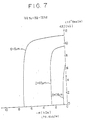
- a grain size of no more than 80 ⁇ m is required to obtain Hc of no less than 1 kOe. Refer to Fig. 6.
- the compounds should have mean crystal grain size ranging from 1 to 90 pm (preferably 1.5 to 80 pm, more preferably 2 to 40 pm). Beyond this range, Hc of below 1 kOe will result.
- the fine particles having a high anisotropy constant are ideally separated individually from one another by nonmagnetic phases, since a high Hc is then obtained.
- the presence of 1 vol % or higher of nonmagnetic phases contributes to the high Hc.
- the nonmagnetic phases should be present in a volume ratio of at least 1 %.
- the presence of 45% or higher of the nonmagnetic phases is not preferable.
- a preferable range is thus 2 to 10 vol %.
- the nonmagnetic phases are mainly comprised of intermetallic compound phases containing much of R, while the presence of a partial oxide phase serves effectively as the nonmagnetic phases.
- the magnetic materials of the present invention may be prepared by the process forming the previous stage of the powder metallurgical process for the preparation of the permanent magnets of the present invention. For example, various elemental metals are melted and cast into alloys having a tetragonal system crystal structure, which are then finely ground into fine powders.
- the magnetic material use may be made of the powdery rare earth oxide R 2 0 3 (a raw material for R). This may be heated with powdery Fe, powdery FeB and a reducing agent (Ca, etc.) for direct reduction.
- the resultant powder alloys show a tetragonal system as well.
- the powder alloys can further be sintered into magnetic materials. This is true for both the Fe-B-R base and the Fe-B-R-M base magnetic materials.
- the rare earth elements used in the magnetic materials and the permanent magnets according to the present invention include light- and heavy-rare earth elements inclusive of Y, and may be applied alone or in combination.
- R includes Nd, Pr, La, Ce, Tb, Dy, Ho, Er, Eu, Sm, Gd, Pm, Tm, Yb, Lu and Y.
- the light rare earth elements amount to no less than 50 at % of the overall rare earth elements R, and particular preference is given to Nd and Pr. More preferably Nd and/or Pr amounts to no less than 50 at % of the overall R.
- the use of one rare earth element will suffice, but, practically, mixtures of two or more rare earth elements such as mischmetal, didymium, etc.
- rare earth elements R are not always pure rare earth elements and, hence, may contain impurities which are inevitably entrained in the production process, as long as they are technically available.
- Boron represented by B may be pure boron or ferroboron, and those containing as impurities AI, Si, C etc. may be used.
- the typical impurities contained in magnetic materials or magnets include Cu, S, C, P, 0 and may be present in total up to 4.0, preferably 3.0, at %.
- Ca, Mg and Si they are allowed to exist each in an amount up to about 8 at %, preferably with the proviso that their total amount shall not exceed about 8 at %.
- Si has an effect upon increases in Curie point, its amount is preferably about 5 at % or less, since iHc decreases sharply in an amount exceeding 5 at %.
- Ca and Mg may abundantly be contained in R raw materials such as commercially available Neodymium or the like.
- the permanent magnets according to the present invention have magnetic properties such as coercive force Hc of >1 kOe, and residual magnetic flux density Br of >4 kG, and provide a maximum energy product (BH)max value which is at least equivalent or superior to the hard ferrite (on the order of up to 4 MGOe).
- the permanent magnet according to the present invention may be subjected to aging and other heat treatments ordinarily applied to conventional permanent magnets, which is understood to be within the concept of the present invention.
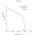
- Table 1 shows the magnetization 4 ⁇ l 16K , as measured at the normal temperature and 16 kOe, and Curie points Tc, as measured at 10 kOe, of various Fe-B-R type alloys. These alloys were prepared by high-frequency melting. After cooling, an ingot was cut into blocks weighing about 0.1 gram. Changes depending on temperature in 4 ⁇ l 10K (magnetization at 10 kOe) of those blocks was measured on a vibrating sample type magnetometer (VSM) to determine their Curie points.
- Fig. 1 is a graphical view showing the change depending on temperature in magnetization of the ingot of 66Fe-14B-20Nd (sample 7 in Table 1), from which Tc is found to be 310°C.
- Table 1 shows high-performance permanent magnets by powder metallurgical sintering.
- Table 2 shows the characteristics of the permanent magnets consisting of various Fe-B-R type compounds prepared by the following steps. For the purpose of comparison, control magnets departing from the scope of the present invention are also described.
- the B-free compounds have a coercive force close to zero or of so small a value that high Hc measuring meters could not be applied, and thus provide no permanent magnets.
- the addition of 4 at % or only 0.64 wt % of B raises Hc to 2.8 kOe (sample No. 4), and there is a sharp increase in Hc with an increase in the amount of B.
- (BH)max increases to 7-20 MGOe and even reaches 35 MGOe or higher.
- the presently invented magnets exhibit high magnetic properties exceeding those of SmCo magnets currently known to be the highest grade magnets.
- Table 2 mainly shows Nd- and Pr-containing compounds but, as shown in the lower part of Table 2, the Fe-B-R type compounds wherein R stands for other rare earth elements or various combinations of rare earth elements also exhibit good permanent magnet properties.
- Fig. 5 illustrates the relationship between (BH)max measured in a similar manner and the Fe-B-Nd composition in the Fe-B-R ternary system.
- the Fe-B-R type compounds exhibit good permanent magnet properties when the amounts of B and R are in a suitable range.
- Hc increases as B increases from zero as shown in Fig. 3.
- Br increases rather steeply, and peaks in the vicinity of 5-7 at % B. A further increase in the amount of B causes Br to decrease.
- the amount of B should be at least 2 at % (preferably at least 3 at %).
- the instantly invented permanent magnets are characterized by possessing high Br after sintering, and often suitable for uses where high magnetic flux densities are needed.
- the Fe-B-R type compounds should contain at most 28 at % B. It is understood that B ranges of 3-27 at % and 4-24 at % are preferable, or the optimum, ranges for attaining (BH)max of ⁇ 7 MGOe and ⁇ 10 MGOe, respectively.
- the optimum amount range for R will now be considered. As shown in Table 2 and Fig. 4, the more the amount of R, the higher Hc will be. Since it is required that permanent magnet materials-have Hc of no less than 1 kOe as mentioned in the foregoing, the amount of R should be 8 at % or higher for that purpose. However, the increase in the amount of R is favourable to increase Hc, but incurs a handling problem since the powders of alloys having a high R content are easy to burn owing to the fact that R is very susceptible to oxidation. In consideration of mass production, it is thus desired that the amount of R be no more than 30 at %. When the amount of R exceeds the upper limit, difficulties would be involved in mass production since alloy powders are easy to burn.
- the amounts of B and R to be applied should be selected from the aforesaid ranges in such a manner that the magnetic properties as aimed at in the present invention are obtained.
- the most preferable magnetic properties are obtained when they are composed of about 8% B, about 15% R and the balance being Fe with impurities, as illustrated in Figs. 3-5 as an embodiment.
- Fig. 2 shows an initial magnetization curve 1, and a demagnetization curve 2 running through the first to the second quadrant, for 68Fe17B15Nd (having the same composition as sample No. 10 of Table 2).
- the initial magnetization curve 1 rises steeply in a low magnetic field, and reaches saturation.
- the demagnetization curve 2 shows very high loop rectangularity. From the form of the initial magnetization curve 1, it is thought that this magnet is a so-called nucleation type permanent magnet since the SmCo type magnets of the nucleation type shows an analogous curve, wherein the coercive force of which is determined by nucleation occurring in the inverted magnetic domain.
- the high loop rectangularity of the demagnetization curve 2 indicates that this magnet is a typical high-performance anisotropic magnet.
- Pulverization (2) in the experimental procedures as aforementioned was carried out for varied periods of time selected in such a manner that the measured mean particle sizes of the powder ranged from 0.5 to 100 ⁇ m, as measured with a sub-sieve-sizer manufactured by Fisher. In this manner, various samples having the compositions as specified in Table 3 were obtained.
- the samples were polished and corroded on their surfaces, and photographed through an optical microscope at a magnification ranging from x 100 to x 1000. Circles having known areas were drawn on the photographs, and divided by lines into eight equal sections. The number of grains present on the diameters were counted and averaged. However, grains on the borders (circumferences) were counted as half grains (this method is known as Heyn's method). Pores were omitted from calculation.
- an alloy having the same composition as Sample No. 8 of Table 3 was prepared by high-frequency melting and casting in a water cooled copper mold.
- the thus cast alloy had Hc of less than 1 kOe in spite of its mean crystal grain size being in a range of 20-80 um.
- the composition comes within the range as defined in the present invention and the mean crystal grain size is 1-80 um, and that, in order to obtain Hc of no less than 4 kOe, the mean crystal grain size should be in a range of 2-40 ⁇ m.
- Control of the crystal grain size of the sintered compact can be carried out by controlling process conditions such as pulverization, sintering, post heat treatment, etc.
- the magnetic material and permanent magnets based on the Fe-B-R alloy according to the present invention can satisfactorily exhibit their own magnetic properties due to the fact that the major phase is formed by the substantially tetragonal crystals of the Fe-B-R type.
- the Fe-B-R type alloy is a novel alloy in view of its Curie point.
- it has further been experimentally ascertained that the presence of the substantially tetragonal crystals of the Fe-B-R type contributes to the exhibition of magnetic properties.
- the Fe-B-R base tetragonal system alloy is unknown in the art, and serves to provide a vital guiding principle for the production of magnetic materials and permanent magnets having high magnetic properties as aimed at in the present invention.
- indices are given at the respective X-ray peaks.
- This structure is characterized by its extremely large lattice constants. No tetragonal system compounds having such large lattice constants are found in any one of the binary system compounds such as R-Fe, Fe-B and B-R.
- Fe-B-R base permanent magnets having various compositions and prepared by the aforesaid manner as well as other various manners were examined with an X-ray diffractometer, XMA and optical microscopy. As a result, the following matters have turned out:
- a tetragonal system compound having macro unit cells which contains as the essential components R, Fe and B and has lattice constants a o of about 0.8 nm (8 A) and Co of about 1.2 nm (12 A), good properties suitable for permanent magnets are obtained.
- Table 4 shows the lattice constants of tetragonal system compounds which'constitute the major phase of typical Fe-B-R type magnets, i.e., occupy 50 vol % or more of the crystal structure.
- the said Fe-B-R tetragonal system compounds are present in a wide compositional range, and may be present in a stable state upon addition of certain elements other than R, Fe and B.
- the Fe-B-R type tetragonal crystal may be substantially tetragonal for producing the desired magnetic properties.
- substantially tetragonal encompasses ones that have a slightly deflected angle between a, b and c axes, i.e., within 1°, or ones that have a. slightly different from b o , e.g., within 1%.
- An alloy of 8 at % B, 16 at % Pr and the balance Fe was pulverized to prepare powders having an average particle size of 15 pm.
- the powders were compacted under a pressure of 19.62x 10 7 Pa (2 t/cm 2 ) and in a magnetic field of 10 kOe, and the resultant compact was sintered at 1090°C for 1 hour in argon of 26.6 Pa (2x10 -1 Torr).
- the major phase contains simultaneously Fe, B and Pr, which amount to 90 vol % thereof.
- the mean crystal grain size was 25 ⁇ m.
- An alloy of 8 at % B, 15 at % Nd and the balance Fe was pulverized to prepare powders having an average particle size of 3 um.
- the powders were compacted in a magnetic field of 10 kOe under a pressure of 19.62x10 7 Pa (2 t/cm 2 ), and sintered at 1100°C for 1 hour in argon of 2666 Pa (2x10 Torr).
- the major phase contains simultaneously Fe, B and Nd, which amount to 90.5 vol % thereof.
- Nonmagnetic compound phases having a R content of no less than 80% were 4% with the remainder being virtually oxides and pores.
- the mean crystal grain size was 15 ⁇ m.
- additional elements M can be applied to the magnetic materials and permanent magnets of the Fe-B-R type, the additional elements M including Ti, Ni, Bi, V, Nb, Ta, Cr, Mo, W, Mn, Al, Sb, Ge, Sn, Zr and Hf, which provides further magnetic materials and permanent magnets of the Fe-B-R-M system.
- Limitation is of course imposed upon the amount of these elements.
- the addition of these elements contribute to the increase in Hc compared with the Fe-R-B ternary system compounds.
- W, Mo, V, AI and Nb have a great effect in this respect.
- the addition of these elements incurs a reduction of Br and, hence, their total amounts should be controlled depending upon the requisite properties.
- the amounts of these elements are respectively limited to no more than the values specified hereinbelow by atomic percent: wherein, when two or more of M are applied, the total amount of M shall be no more than the maximum value among the values specified hereinabove of the M actually added.
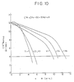
- Figs. 10 to 12 the upper limits of the additional elements M (Ti, Zr, Hf, V, Ta, Nb, Cr, W, Mo, Sb, Sn, Ge and Al) other than Bi, Ni, and Mn may be chosen such that Br is at least equivalent to about 4 kG of hard ferrite.
- M Ti, Zr, Hf, V, Ta, Nb, Cr, W, Mo, Sb, Sn, Ge and Al
- the resulting characteristic curve will be depicted between the characteristic curves of the individual elements in Figs. 10 to 12.
- the amounts of the individual elements M are within the aforesaid ranges, and the total amount thereof is no more than the maximum values allowed for the individual elements which are added and present.
- the total amount of Ti plus V allowed is 9.5 at %, wherein no more than 4.5 at % Ti and no more than 9.5 at % of V can be used.
- a composition comprised of 12-24% R, 3-27% B and the balance being (Fe+M) is preferred for providing (BH)max2:7 MGOe.
- compositions comprised of 12-20% R, 4-24% B and the balance being (Fe+M) for providing (BH)max*10 MGOe wherein (BH)max achieves maximum values of 35 MGOe or higher. Still more preferred compositional ranges are defined principally on the same basis as is the case in the Fe-B-R ternary system.
- (BH)max assumes a value practically similar to that obtained with the case where no M is applied, through the addition of an appropriate amount of M.
- the increase in coercive force serves to stabilize the magnetic properties, so that permanent magnets are obtained which are practically very stable and have a high energy product.
- Ni is a ferromagnetic element. Therefore, the upper limit of Ni is 8%, preferably 4.5%, in view of Hc.
- Mn upon decrease in Br is not strong but larger than is the case with Ni.
- the upper limit of Mn is 8%, preferably 3.5%, in view of iHc.
- Permanent magnet materials were prepared in the following manner.
- the additional elements M are found to be effective for all the Fe-B-R ternary systems wherein R ranges from 8 to 30 at %, B ranges from 2 to 28 at %, with the balance being Fe.
- the elements M are ineffective ( * 12, *13-R is too low-, *14-B is in excess-, *15-R is in excess, and *8 ⁇ *11 ⁇ is without B-).
- Samples 1, and 3 (curves 1, and 3) were obtained based on the samples identical with sample No. 1 (Table 6), sample No. 5 and sample No. 21 (Table 5), respectively.
- the curves 2 and 3 also show the rectangularity or loop squareness in the second quadrant useful for permanent magnets.
- samples Nos. 37-42 51 and 52 Pr as R was used, samples Nos. 48-50 were based on 67Fe-12B-20Nd-1M, and samples Nos. 51 and 52 based on 67Fe-12B-20Pr-1M. Samples Nos. 40, 42-47, 53-58 and 60-65 indicate that even the addition of two or more elements M gives good results.
- Samples No. 56 shows iHc of 4.3 kOe, which is higher than 2.8 kOe of * 16, and sample No. 59 shows iHc of 7.3 kOe which is higher than 5.1 kOe of No. 7.
- the addition of M is effective on both samples.
- the Fe-B-R-M base permanent magnets may contain, in addition to Fe, B, R and M, impurities which are entrained in the process of industrial production.
- Pulverization in the experimental procedures as aforementioned was carried out for varied periods of time selected in such a manner that the measured average particle sizes of the powder ranges from 0.5 to 100 um, as measured with a sub-sieve-sizer manufactured by Fisher. In this manner, various samples having the compositions as specified in Tables 7 and 8 were obtained.
- the Fe-B-R-M system magnetic materials and permanent magnets have basically the same crystal structure as the Fe-B-R system as shown in Table 4, Nos. 13-21, and permit substantially the same impurities as in the case of the Fe-B-R system (see Table 10).
- Table 9 shows the magnetic and physical properties of the typical example according to the present invention and the prior art permanent magnets.
- the present invention provides Co-free, Fe base inexpensive alloys, magnetic materials having high magnetic properties, and sintered, magnetic anisotropic permanent magnets having high remanence, high coercive force, high energy product and high mechanical strength, and thus present a technical breakthrough.
Landscapes
- Chemical & Material Sciences (AREA)
- Engineering & Computer Science (AREA)
- Crystallography & Structural Chemistry (AREA)
- Inorganic Chemistry (AREA)
- Power Engineering (AREA)
- Hard Magnetic Materials (AREA)
- Materials Engineering (AREA)
- Mechanical Engineering (AREA)
- Metallurgy (AREA)
- Organic Chemistry (AREA)
Description
- The present invention relates to novel magnetic materials and permanent magnets based on rare earth elements and iron without recourse to cobalt which is relatively rare and expensive. In the present disclosure, R denotes rare earth elements inclusive yttrium.
- Magnetic materials and permanent magnets are one of the important electric and electronic materials applied in an extensive range from various electrical appliances for domestic use to peripheral terminal devices of large-scaled computers. In view of recent needs for miniaturization and high efficiency of electric and electronic equipment, there has been an increasing demand for upgrading of permanent magnets and in general magnetic materials.
- Now, referring to the permanent magnets, typical permanent magnet materials currently in use are alnico, hard ferrite and rare earth-cobalt magnets. With a recent unstable supply of cobalt, there has been a decreasing demand for alnico magnets containing 20-30 wt % of cobalt. Instead, inexpensive hard'ferrite containing iron oxides as the main component has showed up as major magnet materials. Rare earth-cobalt magnets are very expensive, since they contain 50-65 wt % of cobalt and make use of Sm that is not much found in rare earth ores. However, such magnets have often been used primarily for miniaturized magnetic circuits of high added value, becuase they are by much superior to other magnets in magnetic properties.
- If it could be possible to use, as the main component for the rare earth elements, light rare earth elements that occur abundantly in ores without recourse to cobalt, the rare earth magnets could be used abundantly and with less expense in a wider range. In an effort made to obtain such permanent magnet materials, R-Fe2 base compounds, wherein R is at least one of the rare earth metals, have been investigated. Regarding the following explanations, it is to be noted that the unit "1 G=10-4T", that the unit "1 Oe=0.0796 k - A/m" and that the unit "1 MGOe=7.96 kJ/m3". A. E. Clark has discovered that sputtered amorphous TbFe2 has an energy product of 29.5 MGOe at 4.2°K, and shows a coercive force Hc=3.4 kOe and a maximum energy product (BH)Max=7 MGOe at room temperature upon heat-treatment at 300-500°C. Reportedly, similar investigations on SmFe2 indicated that 9.2 MGOe was reached at 77°K. However, these materials are all obtained by sputtering in the form of thin films that cannot be generally used as magnets for, e.g., speakers or motors. It has further been reported that melt-quenched ribbons of PrFe base alloys show a coercive force Hc as high as 2.8 kOe.
- From Appl. Phys. Lett. 39 (10), 1981, pages 840-842, Koon et al amorphous and crystallized (Feo,82Bo,18)o.gTbo.osLao.os materials are known containing multiphase microstructures. With the melt-quenched amorphous ribbons He of 9 kOe was reached upon annealing at 627°C (Br=5 kG). However, (BH)max is then low due to the unsatisfactory loop squareness of magnetization curves. The magnetic properties are reported to result from binary systems Fe3B and RaFe23 as can be seen from the document IEEE Trans. Magn., Vol. MAG-18, No. 6, 1982 of the same authors.
- L. Kabacoff et al (J. Appl. Phys. 53 (3), 1982, pages 2255-2257) reported that certain binary meltspun Fe-Pr show He in the kOe order at room temperature. This article furthermore describes melt-quenched ribbons of (Fe0.8B0.2)1-xPrx (x=0 to 0.03 atomic ratio) in the amorphous state. Even though he can determine a separate phase resulting from crystallization within the amorphous material, no permanent magnetic properties were identified.
- The non-prepublished EP-A-108474, as far as it is based on its earlier claimed priority, describes permanent magnetic materials with substantially elevated Curie temperature derived by spinning or quenching a melt of FE, B and R having a substantially "amorphous to finely crystalline structure", which term refers to solids having X-ray diffraction patterns which do not indicate the presence of fully crystalline phases.
- These melt-quenched ribbons or sputtered thin films derived by the prior art, are not any practical permanent magnets (bodies) that can be used as such. It would be practically impossible to obtain practical permanent magnets from these ribbons or thin films.
- That is to say, no bulk permanent magnet bodies of any desired shape and size are obtainable from the conventional Fe-B-R base melt-quenched ribbons or R-Fe base sputtered thin films. Due to the unsatisfactory loop squareness (or rectangularity) of the magnetization curves, the Fe-B-R base ribbons heretofore reported are not taken as the practical permanent magnet materials comparable with the conventional, ordinary magnets. Since both the sputtered thin films and the melt-quenched ribbons are magnetically isotropic by nature, it is indeed almost impossible to obtain therefrom magnetically anisotropic (hereinbelow referred to "anisotropic") permanent magnets for the practical purpose.
- Chaban et al (Deper. Akad. Nauk. UKSSR, Ser A (USSR), No. 10, pages 873 to 876 (1979)) reports on his investigations on (Nd, Sm, Gd)-Fe-B ternary systems. In the article (see diagram on page 874) no intermetallic magnetic compound is identifiable.
- In JP-A-52-50598 rare earth cobalt magnets are disclosed which result from compacting a powder of an intermetallic compound comprising 32-42 weight % of rare earth elements and 58-68 weight % of the sum of Co, Fe and Ni, to which at least one of Ta, V, B, Mn, Cr, Zr, Ti and Nb is added in an amount of no more than 2.0 weight %, and sintering the resultant compact. All of these compounds contain Co.
- An essential object of the present invention is to provide novel Co-free magnetic materials and permanent magnets.
- Another object of the present invention is to provide practical permanent magnets from which the aforesaid disadvantages are removed.
- A further object of the present invention is to provide magnetic materials and permanent magnets showing good magnetic properties at room temperature.
- A still further object of the present invention is to provide permanent magnets capable of achieving such high magnetic properties that could not be achieved by R-Co permanent magnets.
- A still further object of the present invention is to provide magnetic materials and permanent magnets which can be formed into any desired shape and size.
- A still further object of the present invention is to provide permanent magnets having magnetic anisotropy, good magnetic properties and excellent mechanical strength.
- A still further object of the present invention is to provide magnetic materials and permanent magnets obtained by making effective use of light rare earth elements occurring abundantly in nature.
- Other objects of the present invention will become apparent from the entire disclosure.
- The present invention provides an alloy comprising Fe-B-R characterized by containing at least one stable compound of the ternary Fe-B-R type, which compound can be magnetized to become a permanent magnet at room temperature and above, wherein R stands for at least one rare earth element including yttrium.
- The present invention further provides a process for preparing such alloys according to claim 13 and use of these alloys according to
claim 17. Besides this, the invention provides a permanent magnet material according toclaim 18 and a process of making same according toclaim 30. Furthermore, the invention provides a magnetic material according to claim 36 comprising at least 50 vol. % of a phase comprising at least one Fe-B-R type compound having a tetragonal structure, wherein R is at least one rare earth element including Y, a sintered magnetic material of a special composition according to claim 48, and a process of making a magnetic material powder showing a tetragonal structure according to claim 49 as well as permanent magnets according toclaims 51 and 55, sintered permanent magnets according toclaim 68 and a process for preparing same according to claim 87. - The novel magnetic materials and permanent magnets according to the present invention are essentially comprised of alloys essentially formed of novel intermetallic compounds and are substantially crystalline, said intermetallic compounds being at least characterized by their novel Curie points Tc.
- According to the first embodiment of the present invention, there is provided a magnetic material which comprises as indispensable components Fe, B and R (at least one of rare earth elements inclusive of Y), and in which a major phase is formed of an intermetallic compound(s) of the Fe-B-R type having a crystal structure of the substantially tetragonal system.
- According to the second embodiment of the present invention, there is provided a sintered magnetic material having a major phase formed of an intermetallic compound(s) consisting essentially of, by atomic percent, 8-30% R (at least one of rare earth elements inclusive of Y), 2-28% B and the balance being Fe with impurities.
- According to the third embodiment of the present invention, there is provided a sintered magnetic material having the same composition as the second embodiment, and having a major phase formed of an intermetallic compound(s) of the substantially tetragonal system.
- According to the fourth embodiment thereof, there is provided a sintered anisotropic permanent magnet consisting essentially of, by atomic percent, 8-30% R (at least one of rare earth elements inclusive of Y), 2-28% B and the balance being Fe with impurities.
- The fifth embodiment thereof provides a sintered anisotropic permanent magnet having a major phase formed of an intermetallic compound(s) of the Fe-B-R type having a crystal structure of the substantially tetragonal system, and consisting essentially of, by atomic percent 8-30% R (at least one of rare earth elements inclusive of Y), 2-28% B and the balance being Fe with impurities.
- "%" denotes atomic % in the present disclosure if not otherwise specified.
- The magnetic materials of the 1st to 3rd embodiments according to the present invention may contain as additional components at least one of elements M selected from the group given below in the amounts of no more than the values specified below, provided that the sum of M is no more than the maximum value among the values specified below of said elements M actually added and the amount of M is more than zero:

- The permanent magnets (the 4th and 5th embodiments) of the present invention may further contain at least one of said additional elements M selected from the group given hereinabove in the amounts of no more than the values specified hereinabove, provided that the amount of M is not zero and the sum of M is no more than the maximum value among the values specified above of said elements M actually added. These embodiments constitute the 9th and 10th embodiments (Fe-B-R-M type) of the present invention.
- With respect to the inventive permanent magnets, practically useful magnetic properties are obtained when the mean crystal grain size of the intermetallic compounds is 1 to 80 pm for the Fe-B-R type, and 1 to 90 !-1m for the Fe-B-R-M type.
- Furthermore, the inventive permanent magnets can exhibit good magnet properties by containing 1 vol % or higher of nonmagnetic intermetallic compound phases.
- The inventive magnetic materials are advantageous in that they can be obtained in the form of at least as-cast alloys, or powdery or granular alloys or a sintered mass, and applied to magnetic recording media (such as magnetic recording tapes) as well as magnetic paints, temperature-sensitive materials and the like. Besides the inventive magnetic materials are useful as the intermediaries for the production of permanent magnets.
-
- Fig. 1 is a graph showing magnetization change characteristics, depending upon temperature, of a block cut out of an ingot of an Fe-B-R alloy (66Fe-14B-20Nd) having a composition within the present invention (magnetization 4nho (kG) versus temperature °C);
- Fig. 2 is a graph showing an
initial magnetization curve 1 anddemagnetization curve 2 of a sintered 68Fe-17B-15Nd magnet (magnetization 4nl (kG) versus magnetic field H(kOe)); - Fig. 3 is a graph showing the relation of iHc(kOe) and Br(kG) versus the B content (at %) for sintered permanent magnets of an Fe-xB-15Nd system.
- Fig. 4 is a graph showing the relation of iHc(kOe) and Br(kG) versus the Nd content (at %) for sintered permanent magnets of an Fe-8B-xNd system;
- Fig. 5 is a Fe-B-Nd ternary system diagram showing compositional ranges corresponding to the maximum energy product (BH)max (MGOe);
- Fig. 6 is a graph depicting the relation between iHc(kOe) and the mean crystal grain size D(pm) for examples according to the present invention;
- Fig. 7 is a graph showing the change of the demagnetization curves depending upon the mean crystal grain size, as observed in the example of a typical composition according to the present invention;
- Fig. 8 is a flow chart illustrative of the experimental procedures of powder X-ray analysis and demagnetization curve measurements;
- Fig. 9 is an X-ray diffraction pattern of the results measured of a typical Fe-B-R sintered body according to the present invention with an X-ray diffractometer;
- Figs. 10-12 are graphs showing the relation of Br(kG) versus the amounts of the additional elements M (at %) for sintered Fe-8B-15Nd-xM systems; and
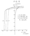
- Fig. 13 is a graph showing magnetization-demagnetization curves for typical embodiments of the present invention.
- It has been noted that R-Fe base compounds provide Co-free permanent magnet materials showing large magnetic anisotropies and magnetic moments. However, it has been found that the R-Fe base compounds containing as R light rare earth elements have extremely low Curie temperatures, and cannot occur in a stable state. For example, PrFe2, is unstable and difficulty is involved in the preparation thereof since a large amount of Pr is required. Thus, studies have been made with a view to preparing novel compounds which are stable at room or elevated temperatures and have high Curie points on the basis of R and Fe.
- Based on the available results of researches, considerations have been made of the relationship between the magnetic properties and the structures of R-Fe base compounds. As a consequence, the following facts have been revealed:
- (1) The interatomic distance between Fe atoms and the environment around the Fe atoms such as the number and kind of the vicinal-most atoms would play a very important role in the magnetic properties of R-Fe base compounds.
- (2) With only combinations of R with Fe, no compound suitable for permanent magnets in a crystalline state would occur.
- In view of these facts, the conclusion has been arrived at that, in the R-Fe base compounds, the presence of a third element is indispensable to alter the environment around Fe atoms and thereby attain the properties suitable for permanent magnets. With this in mind, close examinations have been made of the magnetic properties of R-Fe-X ternary compounds to which various elements were applied. As a result, R-Fe-B compounds (referred to "Fe-B-R type compounds" hereinafter) containing B as X have been discovered. It follows that the Fe-B-R type compounds are unknown compounds, and can provide excellent permanent magnet materials, since they have higher Curie points and large anisotropy constants than the conventional R-Fe compounds.
- Based on this view point, a number of R-Fe base systems have been prepared to seek out novel alloys. As a result, the presence of novel Fe-B-R base compounds showing Curie points of about 300°C has been confirmed, as illustrated in Table 1. Further, as a result of the measurement of the magnetization curves of these alloys with a superconductive magnet, it has been found that the anisotropic magnetic field reaches 100 kOe or higher. Thus, the Fe-B-R base compounds have turned out to be greatly promising for permanent magnet materials.
- The Fe-B-R base alloys have been found to have a high crystal magnetic anisotropy constant Ku and an anisotropy field Ha standing comparison with that of the conventional SmCo type magnet.
- The permanent magnets according to the present invention are prepared by a so-called powder metallurgical process, i.e., sintering, and can be formed into any desired shape and size, as already mentioned. However, desired practical permanent magnets (bodies) were not obtained by such a melt-quenching process as applied in the preparation of amorphous thin film alloys, resulting in no practical coercive force at all.
- On the other hand, no desired magnetic properties (particularly coercive force) were again obtained at all by melting, casting and aging used in the production of Alnico® magnets, etc.
- In accordance with the present invention, however, practical permanent magnets (bodies) of any desired shape are obtained by forming and sintering powder alloys, which magnets have the end good magnetic properties and mechanical strength. For instance, the powder alloys are obtainable by melting, casting and grinding or pulverization.
- The sintered bodies can be used in the as-sintered state as useful permanent magnets, and may of course be subjected to aging usually applied to conventional magnets.
- Noteworthy in this respect is that, as is the case with Fe2B, Fe2P, etc., there are a number of compounds incapable of being made into permanent magnets among those having a macro anisotropy constant, although not elucidatable. In view of the fact that any good properties suitable for the permanent magnets are not obtained until alloys have macro magnetic anisotropy and acquire a suitable microstructure, it has been found that practical permanent magnets are obtained by powdering of cast alloys followed by forming (pressing) and sintering.
- Since the permanent magnets according to the present invention are based on the Fe-B-R system, they need not contain Co. In addition, the starting materials are not expensive, since it is possible to use as R light rare earth elements that occur abundantly in view of the natural resource, whereas it is not necessarily required to use Sm or to use Sm as the main component. In this respect, the invented magnets are prominently useful.
- According to the theory of the single domain particles, magnetic substances having high anisotropy field Ha potentially provide fine particle type magnets with high-performance as is the case with the hard ferrite or SmCo base magnets. From such a viewpoint, sintered, fine particle type magnets were prepared with wide ranges of composition and varied crystal grain size after sintering to determine the permanent magnet properties thereof.
- As a consequence, it has been found that the obtained magnet properties correlate closely with the mean crystal grain size after sintering. In general, have the single magnetic domain, fine particle type magnets have magnetic walls which are formed within each of the particles, if the particles are large. For this reason, inversion of magnetization easily takes place due to shifting of the magnetic walls, resulting in a low Hc. On the contrary, if the particles are reduced in size to below a certain value, no magnetic walls are formed within the particles. For this reason, the inversion of magnetization proceeds only by rotation, resulting in high Hc. The critical size defining the single magnetic domain varies depending upon diverse materials, and has been thought to be about 0.01 um for iron, about 1 11m for hard ferrite, and about 4 11m for SmCo.
- The Hc of various materials increases around their critical size. In the Fe-B-R base permanent magnets of the present embodiment, Hc of 1 kOe or higher is obtained when the mean crystal grain size ranges from 1 to 80 pm, while Hc of 4 kOe or higher is obtained in a range of 2 to 40 µm.
- The permanent magnets according to the present invention are obtained as a sintered body, which enables production with any desired shape and size. Thus the crystal grain size of the sintered body after sintering is of the primary concern. It has experimentally been ascertained that, in order to allow the Hc of the sintered compact to exceed 1 kOe, the mean crystal grain size should be no less than about 1 pm, preferably 1.5 11m, after sintering. In order to obtain sintered bodies having a smaller crystal grain size than this, still finer powders should be prepared prior to sintering. However, it is then believed that the Hc of the sintered bodies decrease considerably, since the fine powders of the Fe-B-R alloys are susceptible to oxidation, the influence of distortion applied upon the fine particles increases, superparamagnetic substances rather than ferromagnetic substances are obtained when the grain size is excessively reduced, or the like. When the crystal grain size exceeds 80 µm, the obtained particles are not single magnetic domain particles, and include magnetic walls therein, so that the inversion of magnetization easily takes place, thus leading to a drop in Hc. A grain size of no more than 80 µm is required to obtain Hc of no less than 1 kOe. Refer to Fig. 6.
- With the systems incorporated with additional eiements M (to be described in detail later), the compounds should have mean crystal grain size ranging from 1 to 90 pm (preferably 1.5 to 80 pm, more preferably 2 to 40 pm). Beyond this range, Hc of below 1 kOe will result.
- With the permanent magnet materials, the fine particles having a high anisotropy constant are ideally separated individually from one another by nonmagnetic phases, since a high Hc is then obtained. To this end, the presence of 1 vol % or higher of nonmagnetic phases contributes to the high Hc. In order that Hc is no less than 1 kOe, the nonmagnetic phases should be present in a volume ratio of at least 1 %. However, the presence of 45% or higher of the nonmagnetic phases is not preferable. A preferable range is thus 2 to 10 vol %. The nonmagnetic phases are mainly comprised of intermetallic compound phases containing much of R, while the presence of a partial oxide phase serves effectively as the nonmagnetic phases.
- Typically, the magnetic materials of the present invention may be prepared by the process forming the previous stage of the powder metallurgical process for the preparation of the permanent magnets of the present invention. For example, various elemental metals are melted and cast into alloys having a tetragonal system crystal structure, which are then finely ground into fine powders.
- As the magnetic material use may be made of the powdery rare earth oxide R203 (a raw material for R). This may be heated with powdery Fe, powdery FeB and a reducing agent (Ca, etc.) for direct reduction. The resultant powder alloys show a tetragonal system as well.
- The powder alloys can further be sintered into magnetic materials. This is true for both the Fe-B-R base and the Fe-B-R-M base magnetic materials.
- The rare earth elements used in the magnetic materials and the permanent magnets according to the present invention include light- and heavy-rare earth elements inclusive of Y, and may be applied alone or in combination. Namely, R includes Nd, Pr, La, Ce, Tb, Dy, Ho, Er, Eu, Sm, Gd, Pm, Tm, Yb, Lu and Y. Preferably, the light rare earth elements amount to no less than 50 at % of the overall rare earth elements R, and particular preference is given to Nd and Pr. More preferably Nd and/or Pr amounts to no less than 50 at % of the overall R. Usually, the use of one rare earth element will suffice, but, practically, mixtures of two or more rare earth elements such as mischmetal, didymium, etc. may be used due to their ease in availability. Sm, Y, La, Ce, Gd and the like may be used in combination with other rare earth elements such as Nd, Pr, etc. These rare earth elements R are not always pure rare earth elements and, hence, may contain impurities which are inevitably entrained in the production process, as long as they are technically available.
- Boron represented by B may be pure boron or ferroboron, and those containing as impurities AI, Si, C etc. may be used.
- The typical impurities contained in magnetic materials or magnets include Cu, S, C, P, 0 and may be present in total up to 4.0, preferably 3.0, at %. With respect to Ca, Mg and Si, they are allowed to exist each in an amount up to about 8 at %, preferably with the proviso that their total amount shall not exceed about 8 at %. It is noted that, although Si has an effect upon increases in Curie point, its amount is preferably about 5 at % or less, since iHc decreases sharply in an amount exceeding 5 at %. In some cases, Ca and Mg may abundantly be contained in R raw materials such as commercially available Neodymium or the like.
- Having an as-sintered composition of 8-30 at % R, 2-28 at % B and the balance Fe with the substantially tetragonal crystal system structure and a mean crystal grain size of 1-80 pm, the permanent magnets according to the present invention have magnetic properties such as coercive force Hc of >1 kOe, and residual magnetic flux density Br of >4 kG, and provide a maximum energy product (BH)max value which is at least equivalent or superior to the hard ferrite (on the order of up to 4 MGOe).
- When the light rare earth elements are mainly used as R (i.e., those elements amount to 50 at % or higher of the overall R) and a composition is applied of 12-24 at % R, 3-27 at % B with the balance being Fe, maximum energy product (BH)max of s7 MGOe is attained. A more preferable as-sintered composition of 12-20 at % R, 4-24 at % B with the balance being Fe, wherein Nd plus Pr amounts to 50% or higher of R provides maximum energy product (BH)max of ≥10 MGOe, and even reaches the highest value of 35 MGOe or higher. As shown in Fig. 5 as an embodiment, compositional ranges each corresponding to the (BH)max values of ≥10, >20, >30 and >35 MGOe are given in the Fe-B-R ternary system.
- After sintering, the permanent magnet according to the present invention may be subjected to aging and other heat treatments ordinarily applied to conventional permanent magnets, which is understood to be within the concept of the present invention.
- The embodiments and effects of the present invention will now be explained with reference to the results of experiments; however, the present invention is not limited to the experiments, examples and the manner of description given hereinbelow. The present invention should be understood to encompass any modifications within the concept derivable from the entire disclosure.
- Table 1 shows the magnetization 4πl16K, as measured at the normal temperature and 16 kOe, and Curie points Tc, as measured at 10 kOe, of various Fe-B-R type alloys. These alloys were prepared by high-frequency melting. After cooling, an ingot was cut into blocks weighing about 0.1 gram. Changes depending on temperature in 4πl10K (magnetization at 10 kOe) of those blocks was measured on a vibrating sample type magnetometer (VSM) to determine their Curie points. Fig. 1 is a graphical view showing the change depending on temperature in magnetization of the ingot of 66Fe-14B-20Nd (sample 7 in Table 1), from which Tc is found to be 310°C.
- Heretofore, there has been found no compound having Tc as shown in Table 1 among the R-Fe alloys. It has thus been found that new stable Fe-B-R type ternary compounds are obtained by adding B to the R-Fe system, and have Tc as shown in Table 1, which varies depending upon the individual R. As shown in Table 1, such new Fe-B-R type ternary compounds occur regardless of the type of R. With most of R, the new compounds have Tc on the order of about 300°C except Ce. It is understood that the known R-Fe alloys are much lower in Tc than the Fe-B-R type ternary compounds of the present invention.
- Although, in Table 1, the measured 4nl,sk does not show saturated magnetization due to the fact that the samples are polycrystalline, the samples all exhibit high values above 6 kOe, and are found to be effective for permanent magnet materials having increased magnetic flux densities.
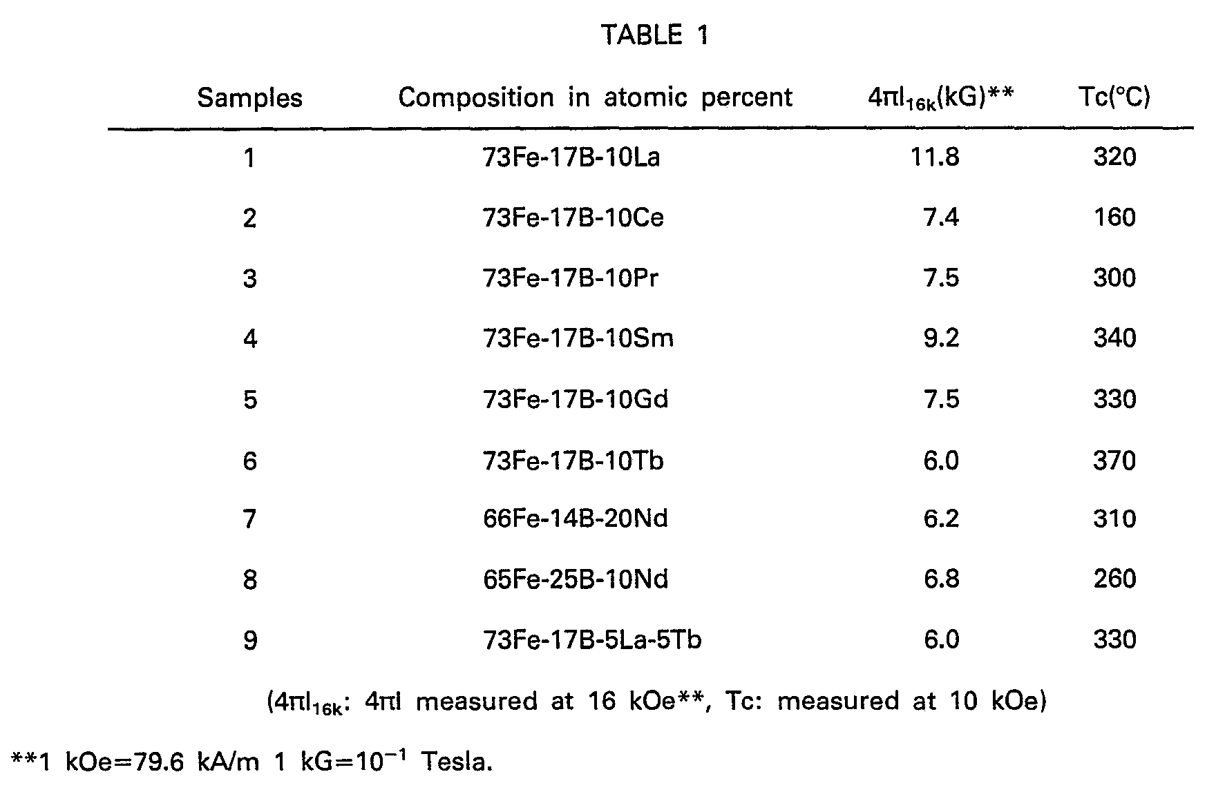
- In what follows, explanation will be made to the fact that the novel compounds found in Table 1 provide high-performance permanent magnets by powder metallurgical sintering. Table 2 shows the characteristics of the permanent magnets consisting of various Fe-B-R type compounds prepared by the following steps. For the purpose of comparison, control magnets departing from the scope of the present invention are also described.
- (1) Alloys were melted by high-frequency melting and cast in a water-cooled copper mold. As the starting materials for Fe, B and R, use was made of, by weight ratio for the purity, 99.9% electrolytic iron, ferroboron alloys of 19.38% B, 5.32 % Al, 0.74% Si, 0.03% C and the balance Fe, and a rare earth element or elements having a purity of 99.7% or higher with the impurities being mainly other rare earth elements, respectively.
- (2) Pulverization: the castings were coarsely ground in a stamp mill until they passed through a 0.42 mm (35-mesh) sieve, and then were finely pulverized in a ball mill for 3 hours to 3-10 urn.
- (3) The resultant powders were oriented in a magnetic field of 10 kOe and compacted under a pressure of 14.71x10⁷ Pa (1.5 t/cm2).
- (4) The resultant compacts were sintered at 1000-1200°C for about one hour in an argon atmosphere and, thereafter, allowed to cool.
- As seen from Table 2, the B-free compounds have a coercive force close to zero or of so small a value that high Hc measuring meters could not be applied, and thus provide no permanent magnets. However, the addition of 4 at % or only 0.64 wt % of B raises Hc to 2.8 kOe (sample No. 4), and there is a sharp increase in Hc with an increase in the amount of B. Incidentally, (BH)max increases to 7-20 MGOe and even reaches 35 MGOe or higher. Thus, the presently invented magnets exhibit high magnetic properties exceeding those of SmCo magnets currently known to be the highest grade magnets. Table 2 mainly shows Nd- and Pr-containing compounds but, as shown in the lower part of Table 2, the Fe-B-R type compounds wherein R stands for other rare earth elements or various combinations of rare earth elements also exhibit good permanent magnet properties.
- As is the case with the samples shown in Table 2, Fe-xB-15Nd and Fe-8B-xNd systems were measured for Br and iHc. The results are summarized in Figs. 3 and 4. Furthermore, Fig. 5 illustrates the relationship between (BH)max measured in a similar manner and the Fe-B-Nd composition in the Fe-B-R ternary system.
- The Fe-B-R type compounds exhibit good permanent magnet properties when the amounts of B and R are in a suitable range. With the Fe-B-R system, Hc increases as B increases from zero as shown in Fig. 3. On the other hand, the residual magnetic flux density Br increases rather steeply, and peaks in the vicinity of 5-7 at % B. A further increase in the amount of B causes Br to decrease.


- In order to meet. the requirement for permanent magnets (materials) to have Hc of at least 1 kOe, the amount of B should be at least 2 at % (preferably at least 3 at %).
- The instantly invented permanent magnets are characterized by possessing high Br after sintering, and often suitable for uses where high magnetic flux densities are needed. In order to be equivalent or superior to the hard ferrite's Br of about 4 kG, the Fe-B-R type compounds should contain at most 28 at % B. It is understood that B ranges of 3-27 at % and 4-24 at % are preferable, or the optimum, ranges for attaining (BH)max of ≥7 MGOe and ≥10 MGOe, respectively.
- The optimum amount range for R will now be considered. As shown in Table 2 and Fig. 4, the more the amount of R, the higher Hc will be. Since it is required that permanent magnet materials-have Hc of no less than 1 kOe as mentioned in the foregoing, the amount of R should be 8 at % or higher for that purpose. However, the increase in the amount of R is favourable to increase Hc, but incurs a handling problem since the powders of alloys having a high R content are easy to burn owing to the fact that R is very susceptible to oxidation. In consideration of mass production, it is thus desired that the amount of R be no more than 30 at %. When the amount of R exceeds the upper limit, difficulties would be involved in mass production since alloy powders are easy to burn.
- It is also desired to decrease the amount of R as much as possible, since R is more expensive than Fe. It is understood that R ranges of 12-24 at % and 12-20 at % are preferable, or the optimum, ranges for making (BH)max be >:7 MGOe and 2:10 MGOe, respectively. Further compositional ranges for higher (BH)max values are also presented, e.g., according to Fig. 5.
- The amounts of B and R to be applied should be selected from the aforesaid ranges in such a manner that the magnetic properties as aimed at in the present invention are obtained. With the presently invented magnets, the most preferable magnetic properties are obtained when they are composed of about 8% B, about 15% R and the balance being Fe with impurities, as illustrated in Figs. 3-5 as an embodiment.
- As a typical embodiment of the sintered, magnetic anisotropic magnets of the Fe-B-R system, Fig. 2 shows an
initial magnetization curve 1, and ademagnetization curve 2 running through the first to the second quadrant, for 68Fe17B15Nd (having the same composition as sample No. 10 of Table 2). - The
initial magnetization curve 1 rises steeply in a low magnetic field, and reaches saturation. Thedemagnetization curve 2 shows very high loop rectangularity. From the form of theinitial magnetization curve 1, it is thought that this magnet is a so-called nucleation type permanent magnet since the SmCo type magnets of the nucleation type shows an analogous curve, wherein the coercive force of which is determined by nucleation occurring in the inverted magnetic domain. The high loop rectangularity of thedemagnetization curve 2 indicates that this magnet is a typical high-performance anisotropic magnet. - Among the compounds given in Table 2, the compounds falling under the scope of the present invention, except those marked *, did all show such a tendency as illustrated in Fig. 2, viz., steep rising of the initial magnetization curve and the high rectangularity of the demagnetization curve, such high permanent magnet properties are by no means obtained by crystallization of the Fe-R or Fe-B-R type amorphous ribbons which are known in the art. There is also not known at all any conventional permanent magnet materials which possess such high properties in the absence of cobalt.
- Pulverization (2) in the experimental procedures as aforementioned was carried out for varied periods of time selected in such a manner that the measured mean particle sizes of the powder ranged from 0.5 to 100 µm, as measured with a sub-sieve-sizer manufactured by Fisher. In this manner, various samples having the compositions as specified in Table 3 were obtained.
- Comparative Examples: To obtain a crystal grain size of 100 11m or greater, the sintered bodies were maintained for prolonged time in an argon atmosphere at a temperature lower than the sintering temperature by 5-20°C.
- From the thus prepared samples having the compositions as specified in Table 3 were obtained magnets which were studied to determine their magnetic properties and their mean crystal grain sizes. The mean crystal grain size referred to herein was measured in the following manner:
- The samples were polished and corroded on their surfaces, and photographed through an optical microscope at a magnification ranging from x 100 to x 1000. Circles having known areas were drawn on the photographs, and divided by lines into eight equal sections. The number of grains present on the diameters were counted and averaged. However, grains on the borders (circumferences) were counted as half grains (this method is known as Heyn's method). Pores were omitted from calculation.
- In Table 3, the samples marked * represent comparative examples. *1, *3, *5 and *11 all depart from the scope of the composition of the magnets according to the present invention.
- From *6, *7 and *17, it is found that Hc drops to 1 kOe or less when the crystal grain size departs from the scope as defined in the present invention.

- A sample having the same composition as No. 4 given in Table 3 and other samples were studied in detail in respect of the relationship between their mean crystal grain size D and Hc. The results are illustrated in Fig. 6, from which it is found that Hc peaks when D is approximately in a range of 3-10 µm, decreases steeply when D is below that range, and drops moderately when D is above that range. Even when the composition varies within the scope as defined in the present invention, the relationship between the average crystal grain size D and Hc is substantially maintained. This indicates that the Fe-B-R system magnets are the single domain-particulate type magnets.
- Apart from the foregoing samples, an alloy having the same composition as Sample No. 8 of Table 3 was prepared by high-frequency melting and casting in a water cooled copper mold. However, the thus cast alloy had Hc of less than 1 kOe in spite of its mean crystal grain size being in a range of 20-80 um.
- From the results given in Table 3 and Figs. 3, 4 and 6, it is evident that, in order for the Fe-B-R system magnets to possess Br of about 4 kG of hard ferrite or more and Hc of no less than 1 kOe, the composition comes within the range as defined in the present invention and the mean crystal grain size is 1-80 um, and that, in order to obtain Hc of no less than 4 kOe, the mean crystal grain size should be in a range of 2-40 µm.
- Fig. 7 shows demagnetization characteristic curves of sample No. 4-77Fe-8B-15Nd-given in Table 3 and Fig. 6 in respect of its typical mean crystal grain sizes (D=0.8, 5 and 65 µm). From this, it is found that the magnets having mean crystal grain size belonging to the scope as defined in the present invention possess high Hc and excellent rectangularity in the second quadrant.
- Control of the crystal grain size of the sintered compact can be carried out by controlling process conditions such as pulverization, sintering, post heat treatment, etc.
- It is believed that the magnetic material and permanent magnets based on the Fe-B-R alloy according to the present invention can satisfactorily exhibit their own magnetic properties due to the fact that the major phase is formed by the substantially tetragonal crystals of the Fe-B-R type. As already discussed, the Fe-B-R type alloy is a novel alloy in view of its Curie point. As will be discussed hereinafter, it has further been experimentally ascertained that the presence of the substantially tetragonal crystals of the Fe-B-R type contributes to the exhibition of magnetic properties. The Fe-B-R base tetragonal system alloy is unknown in the art, and serves to provide a vital guiding principle for the production of magnetic materials and permanent magnets having high magnetic properties as aimed at in the present invention.
- The crystal structure of the Fe-B-R type alloys according to the present invention will now be elucidated with reference to the following experiments.
-
- (1) Starting materials (purity is given by weight %)
- Fe: Electrolytic iron 99.9%
- B: ferroboron, or B having a purity of 99%
- R: 99.7% or higher with impurities being mainly other rare earth elements.
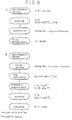
- (2) The experimental procedures are shown in Fig. 8 The experimental results obtained are illustrated as below:
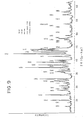
- (1) Fig. 9 illustrates a typical X-ray diffractometric pattern of the Fe-B-Nd (77Fe-15Nd-8B in at %) sintered body showing high properties as measured with a powder X-ray diffractometer. This pattern is very complicated, and can not be explained by any R-Fe, Fe-B or R-B type compounds developed yet in the art.
- (2) XMA measurement of the sintered body of (1) hereinabove under test has indicated that it comprises three or four phases. The major phase simultaneously contains Fe, B and R, the second phase is a R-concentrated phase having an R content of 70 weight % or higher, and the third phase is an Fe-concentrated phase having an Fe content of 80 weight % or higher. The fourth phase is a phase of oxides.
- (3) As a result of analysis of the pattern given in Fig. 9, the sharp peaks included in this pattern may all be explained as the tetragonal crystals of ao=0.88 nm (8.80 A) and Co=1.223 nm (12.23 A).
- In Fig. 9, indices are given at the respective X-ray peaks. The major phase simultaneously containing Fe, B and R, as confirmed in the XMA measurement, has turned out to exhibit such a structure. This structure is characterized by its extremely large lattice constants. No tetragonal system compounds having such large lattice constants are found in any one of the binary system compounds such as R-Fe, Fe-B and B-R.
- (4) Fe-B-R base permanent magnets having various compositions and prepared by the aforesaid manner as well as other various manners were examined with an X-ray diffractometer, XMA and optical microscopy. As a result, the following matters have turned out:
- (i) where a tetragonal system compound having macro unit cells occurs, which contains as the essential components R, Fe and B and has lattice constants ao of about 0.8 nm (8 A) and Co of about 1.2 nm (12 A), good properties suitable for permanent magnets are obtained. Table 4 shows the lattice constants of tetragonal system compounds which'constitute the major phase of typical Fe-B-R type magnets, i.e., occupy 50 vol % or more of the crystal structure.
- In the compounds based on the conventional binary system compounds such as R-Fe, Fe-B and B-R, it is thought that no tetragonal system compounds having such macro unit cells as mentioned above occur. It is thus presumed that no good permanent magnet properties are achieved by those known compounds.
- (ii) Where said tetragonal system compound has a suitable crystal grain size and, besides, nonmagnetic phases occur which contain much R, good properties suitable for permanent magnets are obtained.
- (iii) The said Fe-B-R tetragonal system compounds are present in a wide compositional range, and may be present in a stable state upon addition of certain elements other than R, Fe and B.
- The said Fe-B-R intermetallic compounds have an angle of 90° between a, b and c axes within the tolerance of measurement in most cases, wherein ao=bo*Co, thus these compounds being tetragonal.
- In the present invention, the Fe-B-R type tetragonal crystal may be substantially tetragonal for producing the desired magnetic properties. The term "substantially tetragonal" encompasses ones that have a slightly deflected angle between a, b and c axes, i.e., within 1°, or ones that have a. slightly different from bo, e.g., within 1%.
- The Fe-B-R type permanent magnets of the tetragonal system according to the present invention will now be explained with reference to the following non-restrictive examples.

- An alloy of 8 at % B, 16 at % Pr and the balance Fe was pulverized to prepare powders having an average particle size of 15 pm. The powders were compacted under a pressure of 19.62x 10⁷ Pa (2 t/cm2) and in a magnetic field of 10 kOe, and the resultant compact was sintered at 1090°C for 1 hour in argon of 26.6 Pa (2x10⁻¹ Torr).
- X-ray diffraction has indicated that the major phase of the sintered body is a tetragonal system compound with lattice constants ao=0.885 nm (8.85 A) and Co=1.226 nm (12.26 A). As a consequence of XMA and optical microscopy, it has been found that the major phase contains simultaneously Fe, B and Pr, which amount to 90 vol % thereof. Nonmagnetic compound phases having a R content of no less than 80% assumed 3% of the overall material with the remainder being oxides and pores. The mean crystal grain size was 25 µm.
- The magnetic properties measured are: Br=9.9 kG, iHc=6.5 kOe, and (BH)max=18 MGOe, and are by far higher than those of the conventional amorphous ribbon.
- An alloy of 8 at % B, 15 at % Nd and the balance Fe was pulverized to prepare powders having an average particle size of 3 um. The powders were compacted in a magnetic field of 10 kOe under a pressure of 19.62x10⁷ Pa (2 t/cm2), and sintered at 1100°C for 1 hour in argon of 2666 Pa (2x10 Torr).
- X-ray diffraction has indicated that the major phase of the sintered compact is a tetragonal compound with lattice constants ao=0.880 nm (8.80 A) and Co=1.223 nm (12.23 A). As a consequence of XMA and optical microscopy, it has been found that the major phase contains simultaneously Fe, B and Nd, which amount to 90.5 vol % thereof. Nonmagnetic compound phases having a R content of no less than 80% were 4% with the remainder being virtually oxides and pores. The mean crystal grain size was 15 µm.
- The magnetic properties measured are: Br=12.1 kG. iHc=7.8 kOe and (BH)max=34 MGOe, and are much higher than those of the conventional amorphous ribbon.
- According to the present invention, additional elements M can be applied to the magnetic materials and permanent magnets of the Fe-B-R type, the additional elements M including Ti, Ni, Bi, V, Nb, Ta, Cr, Mo, W, Mn, Al, Sb, Ge, Sn, Zr and Hf, which provides further magnetic materials and permanent magnets of the Fe-B-R-M system. Limitation is of course imposed upon the amount of these elements. The addition of these elements contribute to the increase in Hc compared with the Fe-R-B ternary system compounds. Among others, W, Mo, V, AI and Nb have a great effect in this respect. However, the addition of these elements incurs a reduction of Br and, hence, their total amounts should be controlled depending upon the requisite properties.
- In accordance with the present invention, the amounts of these elements are respectively limited to no more than the values specified hereinbelow by atomic percent:
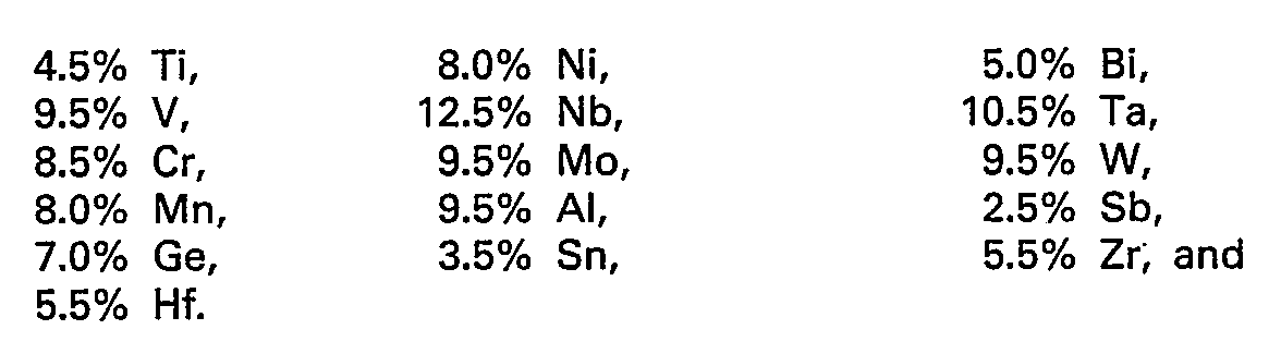
- With respect to the permanent magnets, an increase in iHc due to the addition of M results in increased stability and wide applicability of the magnets. However, the greater the amount of M, the lower the Br and (BH)max will be, due to the fact that they are nonmagnetic elements (except Ni). For this reason, the addition of M is useful provided that (BH)max is at least 4 MGOe.
- To ascertain the effect of M upon Br, Br was measured in varied amounts of M. The results are summarized in Figs. 10 to 12. As seen from Figs. 10 to 12, the upper limits of the additional elements M (Ti, Zr, Hf, V, Ta, Nb, Cr, W, Mo, Sb, Sn, Ge and Al) other than Bi, Ni, and Mn may be chosen such that Br is at least equivalent to about 4 kG of hard ferrite. A preferable range in view of Br should be appreciated from Figs. 10 to 12 by defining the Br range into 6.5 kG, 8 kG, 10 kG or the like stages.
- Based on these figures, the upper limits of the amounts of additional elements M have been put upon the aforesaid values at or below which (BH)max is at least equivalent or superior to about 4 MGOe of hard ferrite.
- When two or more elements M are employed, the resulting characteristic curve will be depicted between the characteristic curves of the individual elements in Figs. 10 to 12. Thus the amounts of the individual elements M are within the aforesaid ranges, and the total amount thereof is no more than the maximum values allowed for the individual elements which are added and present. For example, if Ti and V are present, the total amount of Ti plus V allowed is 9.5 at %, wherein no more than 4.5 at % Ti and no more than 9.5 at % of V can be used.
- A composition comprised of 12-24% R, 3-27% B and the balance being (Fe+M) is preferred for providing (BH)max2:7 MGOe.
- More preferred is a composition comprised of 12-20% R, 4-24% B and the balance being (Fe+M) for providing (BH)max*10 MGOe wherein (BH)max achieves maximum values of 35 MGOe or higher. Still more preferred compositional ranges are defined principally on the same basis as is the case in the Fe-B-R ternary system.
- In general, the more the amount of M, the lower the Br; however, most elements of M serve to increase iHc. Thus, (BH)max assumes a value practically similar to that obtained with the case where no M is applied, through the addition of an appropriate amount of M. The increase in coercive force serves to stabilize the magnetic properties, so that permanent magnets are obtained which are practically very stable and have a high energy product.
- If a large amount of Mn and Ni are incorporated, iHc will decrease; there is only slight decrease in Br due to the fact that Ni is a ferromagnetic element. Therefore, the upper limit of Ni is 8%, preferably 4.5%, in view of Hc.
- The effect of Mn upon decrease in Br is not strong but larger than is the case with Ni. Thus, the upper limit of Mn is 8%, preferably 3.5%, in view of iHc.
- With respect to Bi, its upper limit shall be 5%, since any alloys having a Bi content exceeding 5% cannot practically be produced due to extremely high vapor pressure.
- In what follows, Fe-B-R-M alloys containing various additional elements M will be explained in detail with reference to their experiments and examples.
- Permanent magnet materials were prepared in the following manner.
- (1) Alloys were prepared by high-frequency melting and cast in a copper mold cooled with water. As the starting Fe, B and R, use was made of electrolytic iron having a purity of 99.9% (by weight % so far as the purity is concerned), ferroboron alloys or 99% pure boron, and a rare earth element(s) having a purity of no less than 99.7% (and containing impurities mainly comprising other rare earth metals). The additional elements applied were Ti, Mo, Bi, Mn, Sb, Ni and Ta, those having a purity of 99%, W having a purity of 98%, AI having a purity of 99.9%, Hf having a purity of 95%, and Cu having a purity of 99.9%. As V ferrovanadium containing 81.2% of V; as Nb ferroniobium containing 67.6% of Nb; as Cr ferrochromium containing 61.9% of Cr; and as Zr ferrozirconium containing 75.5% of Zr were used, respectively.
- (2) The resultant as-cast alloys were coarsely ground in a stamp mill until they passed through a 0.42 mm (35-mesh) sieve and, subsequently, finely pulverized to 3-10 !-1m for 3 hours in a ball mill.
- (3) The resultant particles were oriented in a magnetic field (10 kOe) and compacted under a pressure of 14.71 x 10⁷ Pa (1.5 t/cm2=).
- (4) The resultant compacted bodies were sintered at 1000-1200°C for 1 hour in argon and, thereafter, allowed to cool.
- The thus sintered compacts were measured on their iHc, Br and (BH)max, and the results of typical compacts out of these are shown in Table 5 and Table 6. The samples marked * in Table 6 represent comparative samples. In Tables 5 and 6, Fe is of course the remainder, although not specified quantitatively.
- The results have revealed the following facts. Table 5-1 elucidates the effect of the additional elements M in the Fe-8B-15Nd system wherein neodymium is employed, Nd being a typical light-rare earth element. As a result, all the samples (Nos. 1 to 36 inclusive) according to the present embodiment are found to exhibit high coercive force (iHc greater than about 8.0 kOe), compared with sample 1 (iHc=7.3 kOe) given in Table 6. Among others, samples Nos. 31 and 36 possess coercive force of 15 kOe or higher. On the other hand, the samples containing a small amount of M are found to be substantially equivalent to those containing no M with respect to Br see Table 6, sample 1 (12.1 kG). It is found that there is a gradual decrease in Br with the increase in the amount of M. However, all the samples given in Table 5 have a residual magnetic flux density considerably higher than about 4 kG of the conventional hard ferrite.
- In the permanent magnets of the present invention, the additional elements M are found to be effective for all the Fe-B-R ternary systems wherein R ranges from 8 to 30 at %, B ranges from 2 to 28 at %, with the balance being Fe. When B and R depart from the aforesaid ranges, the elements M are ineffective (*12, *13-R is too low-, *14-B is in excess-, *15-R is in excess, and *8―*11―is without B-).
- To elucidate the effect of the addition of the additional elements M, changes in Br were measured in varied amounts of M according to the same testing manner as hereinabove mentioned. The results are summarized in Figs. 10-12 which illustrate that the upper limits of the amounts of the additional elements M are defined as aforementioned.
- As apparent from Figs. 10 to 12, in most cases, the greater the amounts of the additional elements M, the lower the Br resulting in the lower (BH)max, as illustrated in Table 5. However, increases in iHc are vital for such permanent magnets as to be exposed to a very high reversed magnetic field or severe environmental conditions such as high temperature, and provide technical advantages as well as in the case of those with the high (BH)max type. Typically, Fig. 13 illustrates three initial magnetization curves and demagnetization curves 1-3 of (1) Fe-8B-15Nd, (2) Fe-8B-15Nd-1Nb, and (3) Fe-8B-15Nd-2AI (Fe=balance Fe).
-
Samples 1, and 3 (curves 1, and 3) were obtained based on the samples identical with sample No. 1 (Table 6), sample No. 5 and sample No. 21 (Table 5), respectively. Thecurves - In Table 5, for samples Nos. 37-42, 51 and 52 Pr as R was used, samples Nos. 48-50 were based on 67Fe-12B-20Nd-1M, and samples Nos. 51 and 52 based on 67Fe-12B-20Pr-1M. Samples Nos. 40, 42-47, 53-58 and 60-65 indicate that even the addition of two or more elements M gives good results.
- Increased iHc of samples Nos. 5 and 6 of Table 6 are due to high Nd contents. However, the effect of M addition is apparent from samples 48-50, 53-55, 63 and 64, respectively.
- Samples No. 56 shows iHc of 4.3 kOe, which is higher than 2.8 kOe of *16, and sample No. 59 shows iHc of 7.3 kOe which is higher than 5.1 kOe of No. 7. Thus, the addition of M is effective on both samples.
- As samples Nos. 1 and 4, it is also possible to obtain a high coercive force while maintaining a high (BH)max.
- The Fe-B-R-M base permanent magnets may contain, in addition to Fe, B, R and M, impurities which are entrained in the process of industrial production.


- Pulverization in the experimental procedures as aforementioned was carried out for varied periods of time selected in such a manner that the measured average particle sizes of the powder ranges from 0.5 to 100 um, as measured with a sub-sieve-sizer manufactured by Fisher. In this manner, various samples having the compositions as specified in Tables 7 and 8 were obtained.
- Comparative Examples: To obtain a crystal grain size of 100 µm or greater, the sintered bodies were maintained for prolonged time in an argon atmosphere at a temperature lower than the sintered temperature by 5-20°C (Table 7, No. *11).
- From the thus prepared samples having the compositions as specified in Tables 7 and 8 were obtained magnets which were studied to determine their magnetic properties and the mean crystal grain sizes. The results are set forth in Tables 7 and 8. The measurements of the mean crystal grain size were done substantially in the same manner as for the Fe-B-R system aforementioned.
- In Table 7: the samples marked * represent Comparative Examples. Nos. *1-*4, *6 and *8-*10 depart from the scope of the composition of the magnets according to the present invention. Nos. *5, *7, *11 and *12 have the mean crystal grain size outside of the present invention.
- From Nos. *11 and *12, it is found that Hc drops to less 1 kOe when the crystal grain. size departs from the scope as defined in the present invention.
- Samples having the same composition as Nos. 9 and 21 given in Table 8 were studied in detail in respect of the relationship between their mean crystal grain size D and Hc. The results are illustrated in Fig. 6, from which it is found that Hc peaks when D is approximately in a range of 3-10 µm, decreases steeply when D is below that range, and drops moderately when D is above that range. Even when the composition varies within the scope as defined in the present invention, the relationship between the mean crystal grain size D and Hc is substantially maintained. This indicates that the Fe-B-R-M system magnets are the single domain fine particle type magnets as in the case of the Fe-B-R system.
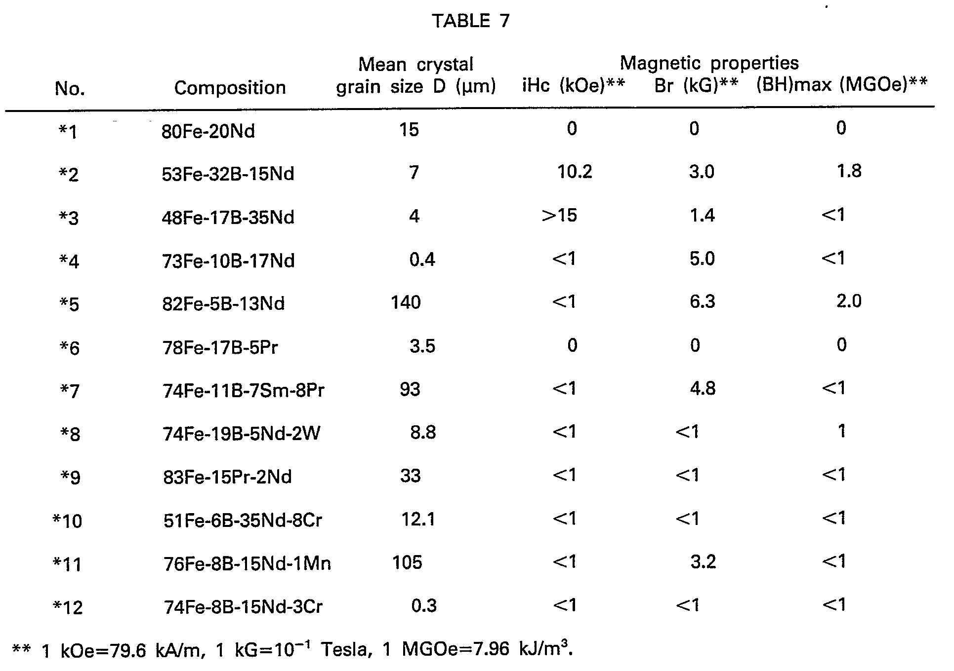


- From the results given in Tables 7 and 8 and Fig. 6, it is apparent that, in order for the Fe-B-R-M system magnets to possess Br of about 4 kG of hard ferrite or more and Hc of no less than 1 kOe, the composition comes within the range as defined in the present embodiment and the mean crystal grain size is 1-90 pm, and that, in order to obtain Hc of no less than 4 kOe, the mean crystal grain size should be in a range of 2-40 um.
- The three curves shown in Fig. 13 for the magnetization and demagnetization were obtained based on the mean crystal grain size of 5-10 µm.
- The Fe-B-R-M system magnetic materials and permanent magnets have basically the same crystal structure as the Fe-B-R system as shown in Table 4, Nos. 13-21, and permit substantially the same impurities as in the case of the Fe-B-R system (see Table 10).
- For the purpose of comparison, Table 9 shows the magnetic and physical properties of the typical example according to the present invention and the prior art permanent magnets.
- Accordingly, the present invention provides Co-free, Fe base inexpensive alloys, magnetic materials having high magnetic properties, and sintered, magnetic anisotropic permanent magnets having high remanence, high coercive force, high energy product and high mechanical strength, and thus present a technical breakthrough.
- It should be understood that the present invention is not limited to the disclosure of the experiments examples and embodiments herein-aforementioned and any modifications apparent in the art may be done without departing from the concept and Claims as set forth hereinbelow.
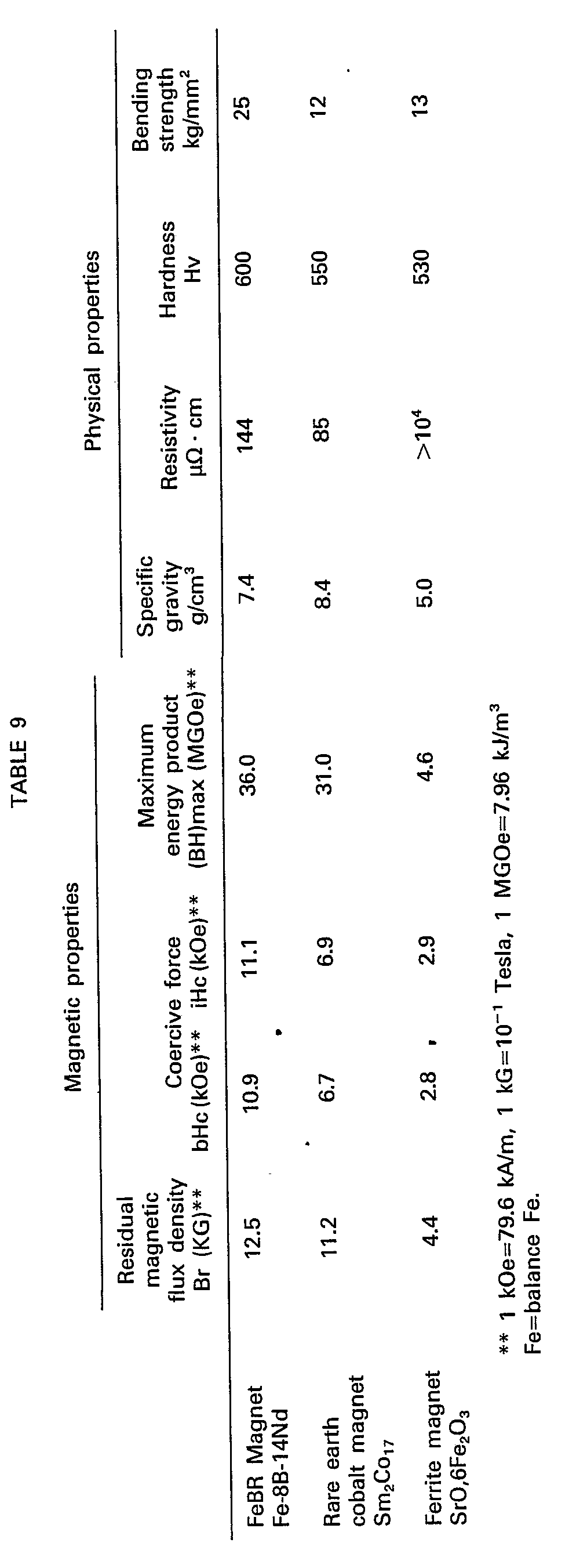
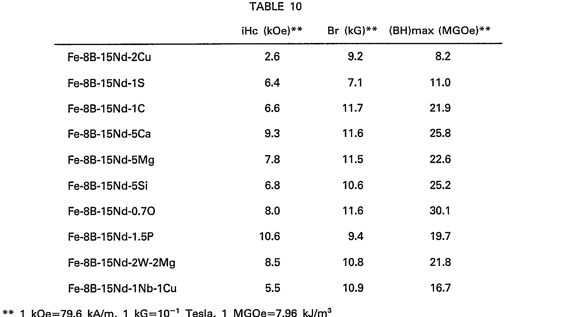
-
- 1. A magnetic material comprising Fe, B and R wherein R is at least one rare earth element including Y, and in which a major phase is formed of at least one intermetallic compound of the Fe-B-R type having a crystal structure of the substantially tetragonal system.
- 2. A sintered magnetic material having a major phase formed of at least one intermetallic compound consisting essentially of, by atomic percent, 8-30 percent R wherein R is at least one of rare earth element including Y, 2-28 percent B and the balance being Fe with impurities.
- 3. A sintered magnetic material having a major phase formed of at least one intermetallic compound of the substantially tetragonal system, and consisting essentially of, by atomic percent, 8-30 percent R, wherein R is at least one rare earth element including Y, 2-28 percent B and the balance being Fe with impurities.
- 4. A sintered anisotropic permanent magnet consisting essentially of, by atomic percent, 8-30 percent R wherein R is at least one rare earth element including Y, 2-28 percent B and the balance being Fe with impurities.
- 5. A sintered anisotropic permanent magnet having a major phase formed of at least one intermetallic compound of the Fe-B-R type having a crystal structure of the substantially tetragonal system, and consisting essentially of, by atomic percent 8-30 percent R wherein R is at least one rare earth element including Y, 2-28 percent B and the balance being Fe with impurities.
- 6. A magnetic material as defined in
embodiment - 7. A permanent magnet as defined in
embodiment 5, in which the substantially tetragonal system amounts to no less than 50 vol %. - 8. A permanent magnet as defined in embodiment 7, which contains no less than 1 vol % of nonmagnetic intermetallic compound phases.
- 9. A permanent magnet as defined in
embodiment - 10. A permanent magnet as defined in embodiment 9, in which the mean crystal grain size is 2 to 40 µm.
- 11. A permanent magnet as defined in
embodiment - 12. A permanent magnet as defined in embodiment 11, in which R is 12-20%, and B is 4-24%.
- 13. A permanent magnet as defined in
embodiment - 14. A permanent magnet as defined in embodiment 13, in which the sum of Nd plus Pr amounts to no less than 50 at % of the overall rare earth elements R.
- 15. A permanent magnet as defined in
embodiment 13 or 14, in which R is about 15%, and B is about 8%. - 16. A permanent magnet as defined in
embodiment - 17. A permanent magnet as defined in embodiment 11, in which the maximum energy product (BH)max is no less than 56 kJ/m3 (7 MGOe).
- 18. A permanent magnet as defined in
embodiment 12, in which the maximum energy product (BH)max is no less than 80 kJ/m3 (10 MGOe). - 19. A permanent magnet as defined in
embodiment 18, in which the maximum energy product (BH)max is no less than 160 kJ/m3 (20 MGOe). - 20. A permanent magnet as defined in embodiment 19, in which the maximum energy product (BH)max is no less than 240 kJ/m3 (30 MGOe).
- 21. A permanent magnet as defined in
embodiment 20, in which the maximum energy product (BH)max is no less than 280 kJ/m3 (35 MGOe). - 22. A magnetic material which comprises Fe, B and R wherein R is at least one rare earth element including Y, and at least one element M selected from the group given below in the amounts of no more than the values specified below, wherein when more than one element comprises M, the sum of M is no more than the maximum value among the values specified below of said elements M actually added and the amount of M is more than zero, and in which a major phase is formed of at least one intermetallic compound of the Fe-B-R type having a crystal structure of the substantially tetragonal system:

- 23. A sintered magnetic material having a major phase formed of at least one intermetallic compound consisting essentially of, by atomic percent, 8-30 percent R wherein R is at least one rare earth element including Y, 2-28 percent B, at least one additional element M selected from the group given below in the amounts of no more than the values specified below wherein when more than one element comprises M, the sum of M is no more than the maximum value among the values specified below of said elements M actually added and the amount of M is more than zero, and the balance being Fe with impurities:
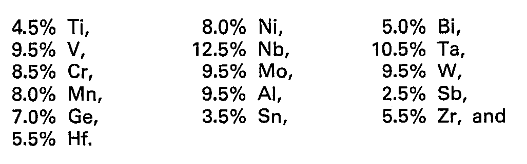
- 24. A sintered magnetic material having a major phase formed of at least one intermetallic compound of the substantially tetragonal system, and consisting essentially of, by atomic percent, 8-30 percent R wherein R is at least one rare earth element including Y, 2-28 percent B, at least one additional element M selected from the group given below in the amounts of no more than the values specified below wherein when more than one element comprises M, the sum of M is no more than the maximum value among the values specified below of said elements M actually added and the amount of M is more than zero, and the balance being Fe with impurities:

- 25. A sintered anisotropic permanent magnet consisting essentially of, by atomic percent, 8-30 percent R, wherein R is at least one rare earth element including Y, 2-28 percent B, at least one additional element M selected from the group given below in the amounts of no more than the values specified below, wherein the amount of M is not zero and wherein when more than one element comprises M, the sum of M is no more than the maximum value among the values specified below of said elements M actually added, and the balance being Fe with impurities:
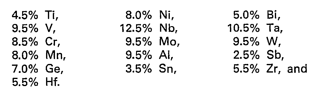
- 26. A sintered anisotropic permanent magnet having a major phase formed of at least one intermetallic compound of the Fe-B-R type having a crystal structure of the substantially tetragonal system and consisting essentially of, by atomic percent, 8-30 percent R wherein R is at least one rare earth element including Y, 2-28 percent B, at least one additional element M selected from the group given below in the amounts no more than the values specified below, wherein the amount of M is not zero and wherein when more than one element comprises M, the sum of M is no more than the maximum value among the values specified below of said elements M actually added, and the balance being Fe with impurities:
- 27. A magnetic material as defined in embodiment 22 or 24, in which the substantially tetragonal system amounts to no less than 50 vol %.
- 28. A permanent magnet as defined in embodiment 26, in which the substantially tetragonal system amounts to no less than 50 vol %.
- 29. A permanent magnet as defined in embodiment 28, which contains no less than 1 vol % of nonmagnetic intermetallic compound phases.
- 30. A permanent magnet as defined in
embodiment 25 or 26, in which the mean crystal grain size is 1 to 90 pm. - 31. A permanent magnet as defined in
embodiment 20, in which the mean crystal grain size is 2 to 40 pm. - 32. A permanent magnet as defined in
embodiment 25 or 26, in which R is 12 to 24%, and B is 3 to 27%. - 33. A permanent magnet as defined in
embodiment 32, in which R is 12 to 20%, and B is 4 to 24%. - 34. A permanent magnet as defined in embodiment 28 or 29, in which the light rare earth element(s) amounts to no less than 50 at % of the overall rare earth elements R.
- 35. A permanent magnet as defined in embodiment 34, in which the sum of Nd plus Pr amounts to no less than 50 at % of the overall rare earth elements R.
- 36. A permanent magnet as defined in
embodiment 34 or 35, in which R is about 15%, and B is about 8%. - 37. A permanent magnet as defined in
embodiment 25 or 26, in which the maximum energy product (BH)max is no less than 32 kJ/m3 (4 MGOe). - 38. A permanent magnet as defined in
embodiment 32, in which the maximum energy product (BH)max is no less than 56 kJ/m3 (7 MGOe). - 39. A permanent magnet as defined in embodiment 33, in which the maximum energy product (BH)max is no less than 80 kJ/m3 (10 MGOe).
- 40. A permanent magnet as defined in embodiment 39, in which the maximum energy product (BH)max is no less than 160 kJ/m3 (20 MGOe).
- 41. A permanent magnet as defined in
embodiment 40, in which the maximum energy product (BH)max is no less than 240 kJ/m3 (30 MGOe). - 42. A permanent magnet as defined in embodiment 41, in which the maximum energy product (BH)max is no less than 280 kJ/m3 (35 MGOe).
Claims (102)


Applications Claiming Priority (21)
| Application Number | Priority Date | Filing Date | Title |
|---|---|---|---|
| JP145072/82 | 1982-08-21 | ||
| JP57145072A JPS5946008A (en) | 1982-08-21 | 1982-08-21 | Permanent magnet |
| JP14507282 | 1982-08-21 | ||
| JP57200204A JPS5989401A (en) | 1982-11-15 | 1982-11-15 | Permanent magnet |
| JP20020482 | 1982-11-15 | ||
| JP200204/82 | 1982-11-15 | ||
| JP5814/83 | 1983-01-19 | ||
| JP581483 | 1983-01-19 | ||
| JP58005814A JPS59132105A (en) | 1983-01-19 | 1983-01-19 | Permanent magnet |
| JP37898/83 | 1983-03-08 | ||
| JP58037898A JPS59163804A (en) | 1983-03-08 | 1983-03-08 | Permanent magnet |
| JP37896/83 | 1983-03-08 | ||
| JP3789683 | 1983-03-08 | ||
| JP58037896A JPS59163802A (en) | 1983-03-08 | 1983-03-08 | Permanent magnet material |
| JP3789883 | 1983-03-08 | ||
| JP58084859A JPS59211558A (en) | 1983-05-14 | 1983-05-14 | Permanent magnet material |
| JP8485983 | 1983-05-14 | ||
| JP84859/83 | 1983-05-14 | ||
| JP9487683 | 1983-05-31 | ||
| JP94876/83 | 1983-05-31 | ||
| JP58094876A JPH0778269B2 (en) | 1983-05-31 | 1983-05-31 | Rare earth / iron / boron tetragonal compound for permanent magnet |
Publications (4)
| Publication Number | Publication Date |
|---|---|
| EP0101552A2 EP0101552A2 (en) | 1984-02-29 |
| EP0101552A3 EP0101552A3 (en) | 1985-03-20 |
| EP0101552B1 true EP0101552B1 (en) | 1989-08-09 |
| EP0101552B2 EP0101552B2 (en) | 2002-12-11 |
Family
ID=27563324
Family Applications (1)
| Application Number | Title | Priority Date | Filing Date |
|---|---|---|---|
| EP83106573A Expired - Lifetime EP0101552B2 (en) | 1982-08-21 | 1983-07-05 | Magnetic materials, permanent magnets and methods of making those |
Country Status (6)
| Country | Link |
|---|---|
| US (2) | US4770723A (en) |
| EP (1) | EP0101552B2 (en) |
| CA (1) | CA1316375C (en) |
| DE (2) | DE101552T1 (en) |
| HK (1) | HK68290A (en) |
| SG (1) | SG48490G (en) |
Cited By (63)
| Publication number | Priority date | Publication date | Assignee | Title |
|---|---|---|---|---|
| US4541877A (en) * | 1984-09-25 | 1985-09-17 | North Carolina State University | Method of producing high performance permanent magnets |
| JPS6131303A (en) * | 1984-06-29 | 1986-02-13 | セントル・ナシヨナル・ド・ラ・ルシエルシエ・サイエンテイフイク | Magnetic rare earth/iron/boron hydrides and rare earth/cobalt/boron hydrides, their production methods and uses |
| US4585473A (en) * | 1984-04-09 | 1986-04-29 | Crucible Materials Corporation | Method for making rare-earth element containing permanent magnets |
| US4588439A (en) * | 1985-05-20 | 1986-05-13 | Crucible Materials Corporation | Oxygen containing permanent magnet alloy |
| EP0184722A1 (en) * | 1984-11-27 | 1986-06-18 | Sumitomo Special Metals Co., Ltd. | Rare earth alloy powders and process of producing same |
| EP0124655A3 (en) * | 1983-05-06 | 1986-09-10 | Sumitomo Special Metals Co., Ltd. | Isotropic permanent magnets and process for producing same |
| EP0197712A1 (en) * | 1985-03-28 | 1986-10-15 | Kabushiki Kaisha Toshiba | Rare earth-iron-boron-based permanent magnet |
| EP0208807A1 (en) * | 1985-06-14 | 1987-01-21 | Union Oil Company Of California | Rare earth-iron-boron permanent magnets |
| DE3626406A1 (en) * | 1985-08-13 | 1987-02-26 | Seiko Epson Corp | METHOD FOR PRODUCING PERMANENT MAGNETS BASED ON RARE EARTH METALS |
| EP0216254A1 (en) * | 1985-09-10 | 1987-04-01 | Kabushiki Kaisha Toshiba | Permanent magnet |
| US4664724A (en) * | 1984-09-14 | 1987-05-12 | Kabushiki Kaisha Toshiba | Permanent magnetic alloy and method of manufacturing the same |
| EP0237416A1 (en) * | 1986-03-06 | 1987-09-16 | Shin-Etsu Chemical Co., Ltd. | A rare earth-based permanent magnet |
| EP0237587A1 (en) * | 1986-03-06 | 1987-09-23 | Sumitomo Special Metals Co., Ltd. | Method for producing a rare earth alloy and rare earth alloy |
| EP0242187A1 (en) * | 1986-04-15 | 1987-10-21 | TDK Corporation | Permanent magnet and method of producing same |
| US4721538A (en) * | 1984-07-10 | 1988-01-26 | Crucible Materials Corporation | Permanent magnet alloy |
| EP0261579A1 (en) * | 1986-09-16 | 1988-03-30 | Tokin Corporation | A method for producing a rare earth metal-iron-boron permanent magnet by use of a rapidly-quenched alloy powder |
| GB2196479A (en) * | 1986-10-20 | 1988-04-27 | Philips Electronic Associated | Method and apparatus for the manufacture of rare earth transition metal alloy magnets |
| USRE32714E (en) * | 1984-09-25 | 1988-07-19 | North Carolina State University | Method of producing high performance permanent magnets |
| US4765848A (en) * | 1984-12-31 | 1988-08-23 | Kaneo Mohri | Permanent magnent and method for producing same |
| EP0280372A1 (en) * | 1987-02-27 | 1988-08-31 | Philips Electronics Uk Limited | Improved method for the manufacture of rare earth transition metal alloy magnets |
| EP0286324A1 (en) * | 1987-04-02 | 1988-10-12 | The University Of Birmingham | Magnets |
| EP0285990A1 (en) * | 1987-03-31 | 1988-10-12 | Seiko Epson Corporation | A rare-earth permanent magnet |
| US4792367A (en) * | 1983-08-04 | 1988-12-20 | General Motors Corporation | Iron-rare earth-boron permanent |
| US4814139A (en) * | 1986-01-16 | 1989-03-21 | Hitachi Metals, Ltd. | Permanent magnet having good thermal stability and method for manufacturing same |
| US4844754A (en) * | 1983-08-04 | 1989-07-04 | General Motors Corporation | Iron-rare earth-boron permanent magnets by hot working |
| WO1989008318A1 (en) * | 1988-02-29 | 1989-09-08 | Sumitomo Special Metals Company Limited | Magnetically anisotropic sintered magnets |
| US4878958A (en) * | 1986-05-30 | 1989-11-07 | Union Oil Company Of California | Method for preparing rare earth-iron-boron permanent magnets |
| US4881986A (en) * | 1986-11-26 | 1989-11-21 | Tokin Corporation | Method for producing a rare earth metal-iron-boron anisotropic sintered magnet from rapidly-quenched rare earth metal-iron-boron alloy ribbon-like flakes |
| US4888506A (en) * | 1987-07-09 | 1989-12-19 | Hitachi Metals, Ltd. | Voice coil-type linear motor |
| US4891078A (en) * | 1984-03-30 | 1990-01-02 | Union Oil Company Of California | Rare earth-containing magnets |
| US4892596A (en) * | 1988-02-23 | 1990-01-09 | Eastman Kodak Company | Method of making fully dense anisotropic high energy magnets |
| US4898613A (en) * | 1985-02-26 | 1990-02-06 | Sumitomo Special Metals Co. Ltd. | Rare earth alloy powder used in production of permanent magnets |
| US4902360A (en) * | 1987-02-04 | 1990-02-20 | Crucible Materials Corporation | Permanent magnet alloy for elevated temperature applications |
| US4908076A (en) * | 1984-04-24 | 1990-03-13 | Yamaha Corporation | FE-B magnets containing Nd-Pr-Ce rare earth elements |
| US4921551A (en) * | 1986-01-29 | 1990-05-01 | General Motors Corporation | Permanent magnet manufacture from very low coercivity crystalline rare earth-transition metal-boron alloy |
| US4933009A (en) * | 1985-06-14 | 1990-06-12 | Union Oil Company Of California | Composition for preparing rare earth-iron-boron-permanent magnets |
| US4935075A (en) * | 1986-06-12 | 1990-06-19 | Kabushiki Kaisha Toshiba | Permanent magnet |
| US4942098A (en) * | 1987-03-26 | 1990-07-17 | Sumitomo Special Metals, Co., Ltd. | Corrosion resistant permanent magnet |
| US4952252A (en) * | 1985-06-14 | 1990-08-28 | Union Oil Company Of California | Rare earth-iron-boron-permanent magnets |
| US4959273A (en) * | 1988-09-20 | 1990-09-25 | Sumitomo Special Metals Co., Ltd. | Corrosion-resistant permanent magnet and method for preparing the same |
| US4983232A (en) * | 1987-01-06 | 1991-01-08 | Hitachi Metals, Ltd. | Anisotropic magnetic powder and magnet thereof and method of producing same |
| US4985086A (en) * | 1987-09-10 | 1991-01-15 | Hitachi Metals, Ltd. | Method and apparatus for producing magnetically anisotropic Nd-Fe-B magnet material |
| US4985085A (en) * | 1988-02-23 | 1991-01-15 | Eastman Kodak Company | Method of making anisotropic magnets |
| DE3928389A1 (en) * | 1989-08-28 | 1991-03-14 | Schramberg Magnetfab | PERMANENT MAGNET |
| US5000796A (en) * | 1988-02-23 | 1991-03-19 | Eastman Kodak Company | Anisotropic high energy magnets and a process of preparing the same |
| GB2238797A (en) * | 1989-12-08 | 1991-06-12 | Philips Electronic Associated | Manufacture of rare-earth materials and permanent magnets |
| US5041171A (en) * | 1986-07-18 | 1991-08-20 | U.S. Philips Corporation | Hard magnetic material |
| US5055146A (en) * | 1984-07-10 | 1991-10-08 | Crucible Materials Corporation | Permanent magnet alloy |
| US5110377A (en) * | 1984-02-28 | 1992-05-05 | Sumitomo Special Metals Co., Ltd. | Process for producing permanent magnets and products thereof |
| US5286307A (en) * | 1989-09-06 | 1994-02-15 | Sps Technologies, Inc. | Process for making Nd-B-Fe type magnets utilizing a hydrogen and oxygen treatment |
| US5292380A (en) * | 1987-09-11 | 1994-03-08 | Hitachi Metals, Ltd. | Permanent magnet for accelerating corpuscular beam |
| US5354354A (en) * | 1991-10-22 | 1994-10-11 | Th. Goldschmidt Ag | Method for producing single-phase, incongruently melting intermetallic phases |
| USRE34838E (en) * | 1984-12-31 | 1995-01-31 | Tdk Corporation | Permanent magnet and method for producing same |
| AT398861B (en) * | 1991-02-11 | 1995-02-27 | Boehler Ybbstalwerke | SINTERED PERMANENT MAGNET (MATERIAL) AND METHOD FOR THE PRODUCTION THEREOF |
| EP0522177B1 (en) * | 1991-01-28 | 1995-07-12 | Mitsubishi Materials Corporation | Anisotropic Rare Earth Magnet |
| JPH07183149A (en) * | 1994-10-24 | 1995-07-21 | Toshiba Corp | Permanent magnet manufacturing method |
| US5449417A (en) * | 1988-10-04 | 1995-09-12 | Hitachi Metals, Ltd. | R-Fe-B magnet alloy, isotropic bonded magnet and method of producing same |
| US5478411A (en) * | 1990-12-21 | 1995-12-26 | Provost, Fellows And Scholars Of The College Of The Holy And Undivided Trinity Of Queen Elizabeth Near Dublin | Magnetic materials and processes for their production |
| US5630885A (en) * | 1992-02-15 | 1997-05-20 | Santoku Metal Industry, Co., Ltd. | Alloy ingot for permanent magnet, anisotropic powders for permanent magnet, method for producing same and permanent magnet |
| US5634987A (en) * | 1992-07-16 | 1997-06-03 | The University Of Sheffield | Magnetic materials and method of making them |
| US6136099A (en) * | 1985-08-13 | 2000-10-24 | Seiko Epson Corporation | Rare earth-iron series permanent magnets and method of preparation |
| EP0571002B2 (en) † | 1989-08-25 | 2003-01-02 | Dowa Mining Co., Ltd. | Permanent magnet alloy having improved resistance to oxidation and process for production thereof |
| USRE38042E1 (en) * | 1987-01-06 | 2003-03-25 | Hitachi Metals, Ltd. | Anisotropic magnetic powder and magnet thereof and method of producing same |
Families Citing this family (130)
| Publication number | Priority date | Publication date | Assignee | Title |
|---|---|---|---|---|
| US5466308A (en) * | 1982-08-21 | 1995-11-14 | Sumitomo Special Metals Co. Ltd. | Magnetic precursor materials for making permanent magnets |
| US5194098A (en) * | 1982-08-21 | 1993-03-16 | Sumitomo Special Metals Co., Ltd. | Magnetic materials |
| CA1316375C (en) * | 1982-08-21 | 1993-04-20 | Masato Sagawa | Magnetic materials and permanent magnets |
| DE3379084D1 (en) * | 1982-09-27 | 1989-03-02 | Sumitomo Spec Metals | Permanently magnetizable alloys, magnetic materials and permanent magnets comprising febr or (fe,co)br (r=vave earth) |
| US4767474A (en) * | 1983-05-06 | 1988-08-30 | Sumitomo Special Metals Co., Ltd. | Isotropic magnets and process for producing same |
| US4597938A (en) * | 1983-05-21 | 1986-07-01 | Sumitomo Special Metals Co., Ltd. | Process for producing permanent magnet materials |
| JPS6032306A (en) * | 1983-08-02 | 1985-02-19 | Sumitomo Special Metals Co Ltd | Permanent magnet |
| CA1236381A (en) * | 1983-08-04 | 1988-05-10 | Robert W. Lee | Iron-rare earth-boron permanent magnets by hot working |
| DE3479940D1 (en) * | 1983-10-26 | 1989-11-02 | Gen Motors Corp | High energy product rare earth-transition metal magnet alloys containing boron |
| CA1271394A (en) * | 1985-02-25 | 1990-07-10 | Karen S. Canavan | Enhanced remanence permanent magnetic alloy and bodies thereof and method of preparing same |
| US5538565A (en) * | 1985-08-13 | 1996-07-23 | Seiko Epson Corporation | Rare earth cast alloy permanent magnets and methods of preparation |
| US4954186A (en) * | 1986-05-30 | 1990-09-04 | Union Oil Company Of California | Rear earth-iron-boron permanent magnets containing aluminum |
| US4747874A (en) * | 1986-05-30 | 1988-05-31 | Union Oil Company Of California | Rare earth-iron-boron permanent magnets with enhanced coercivity |
| DE3783975T2 (en) * | 1986-07-23 | 1993-05-27 | Hitachi Metals Ltd | PERMANENT MAGNET WITH GOOD THERMAL STABILITY. |
| EP0304054B1 (en) * | 1987-08-19 | 1994-06-08 | Mitsubishi Materials Corporation | Rare earth-iron-boron magnet powder and process of producing same |
| DE3740157A1 (en) * | 1987-11-26 | 1989-06-08 | Max Planck Gesellschaft | SINTER MAGNET BASED ON FE-ND-B |
| JPH01139738A (en) * | 1987-11-27 | 1989-06-01 | Hitachi Metals Ltd | Method and apparatus for magnetic material having magnetic anisotropy |
| JP2970809B2 (en) * | 1987-12-28 | 1999-11-02 | 信越化学工業株式会社 | Rare earth permanent magnet |
| US5000800A (en) * | 1988-06-03 | 1991-03-19 | Masato Sagawa | Permanent magnet and method for producing the same |
| IE891581A1 (en) * | 1988-06-20 | 1991-01-02 | Seiko Epson Corp | Permanent magnet and a manufacturing method thereof |
| JP2787580B2 (en) * | 1988-10-06 | 1998-08-20 | 眞人 佐川 | Nd-Fe-B based sintered magnet with excellent heat treatment |
| US4931092A (en) * | 1988-12-21 | 1990-06-05 | The Dow Chemical Company | Method for producing metal bonded magnets |
| US5266128A (en) * | 1989-06-13 | 1993-11-30 | Sps Technologies, Inc. | Magnetic materials and process for producing the same |
| US5244510A (en) * | 1989-06-13 | 1993-09-14 | Yakov Bogatin | Magnetic materials and process for producing the same |
| US5114502A (en) * | 1989-06-13 | 1992-05-19 | Sps Technologies, Inc. | Magnetic materials and process for producing the same |
| US5122203A (en) * | 1989-06-13 | 1992-06-16 | Sps Technologies, Inc. | Magnetic materials |
| US5183630A (en) * | 1989-08-25 | 1993-02-02 | Dowa Mining Co., Ltd. | Process for production of permanent magnet alloy having improved resistence to oxidation |
| US5269855A (en) * | 1989-08-25 | 1993-12-14 | Dowa Mining Co., Ltd. | Permanent magnet alloy having improved resistance |
| EP0518903B1 (en) * | 1990-03-06 | 1997-07-16 | United States Bronze Powders Incorporated | Improvements in and relating to powder metallurgy compositions |
| US5250206A (en) * | 1990-09-26 | 1993-10-05 | Mitsubishi Materials Corporation | Rare earth element-Fe-B or rare earth element-Fe-Co-B permanent magnet powder excellent in magnetic anisotropy and corrosion resistivity and bonded magnet manufactured therefrom |
| DE4133214C2 (en) * | 1990-10-05 | 1996-11-07 | Hitachi Metals Ltd | Permanent magnet material made of iron-rare earth metal alloy |
| US5242508A (en) * | 1990-10-09 | 1993-09-07 | Iowa State University Research Foundation, Inc. | Method of making permanent magnets |
| US5240513A (en) * | 1990-10-09 | 1993-08-31 | Iowa State University Research Foundation, Inc. | Method of making bonded or sintered permanent magnets |
| US5427734A (en) * | 1992-06-24 | 1995-06-27 | Sumitomo Special Metals Co., Ltd. | Process for preparing R-Fe-B type sintered magnets employing the injection molding method |
| US5403408A (en) * | 1992-10-19 | 1995-04-04 | Inland Steel Company | Non-uniaxial permanent magnet material |
| RU2113742C1 (en) * | 1993-07-06 | 1998-06-20 | Сумитомо Спешиал Металз Ко., Лтд. | Permanent-magnet materials and their manufacturing processes |
| US5454998A (en) * | 1994-02-04 | 1995-10-03 | Ybm Technologies, Inc. | Method for producing permanent magnet |
| US5666635A (en) | 1994-10-07 | 1997-09-09 | Sumitomo Special Metals Co., Ltd. | Fabrication methods for R-Fe-B permanent magnets |
| RU2118007C1 (en) * | 1997-05-28 | 1998-08-20 | Товарищество с ограниченной ответственностью "Диполь-М" | Material for permanent magnets |
| US6261386B1 (en) * | 1997-06-30 | 2001-07-17 | Wisconsin Alumni Research Foundation | Nanocrystal dispersed amorphous alloys |
| US6332933B1 (en) | 1997-10-22 | 2001-12-25 | Santoku Corporation | Iron-rare earth-boron-refractory metal magnetic nanocomposites |
| JPH11307327A (en) * | 1998-04-22 | 1999-11-05 | Sanei Kasei Kk | Composition for permanent magnet |
| TW493185B (en) | 1998-07-13 | 2002-07-01 | Santoku Inc | High performance iron-rare earth-boron-refractory-cobalt nanocomposites |
| TW383249B (en) | 1998-09-01 | 2000-03-01 | Sumitomo Spec Metals | Cutting method for rare earth alloy by annular saw and manufacturing for rare earth alloy board |
| CN1187152C (en) * | 1999-03-03 | 2005-02-02 | 株式会社新王磁材 | Sintering box for rareearth magnet sintering and method for making rareearth magnet sintered and processed by said box |
| US6524399B1 (en) | 1999-03-05 | 2003-02-25 | Pioneer Metals And Technology, Inc. | Magnetic material |
| US7195661B2 (en) * | 1999-03-05 | 2007-03-27 | Pioneer Metals And Technology, Inc. | Magnetic material |
| DE10022717C2 (en) * | 1999-05-11 | 2003-08-28 | Sumitomo Spec Metals | Device and method for pressing powder of a rare earth metal alloy |
| TW440494B (en) | 1999-05-13 | 2001-06-16 | Sumitomo Spec Metals | Machining method of rare earth alloy and manufacture of rare earth magnet using it |
| JP2001123201A (en) | 1999-08-17 | 2001-05-08 | Sanei Kasei Kk | Method for producing sinetred permanent magnet |
| US6344168B1 (en) | 1999-08-30 | 2002-02-05 | Sumitomo Special Metals Co., Ltd. | Method of producing R-Fe-B type sintered magnet, method of preparing alloy powder material for R-Fe-B type sintered magnet, and method of preserving the same |
| US6261387B1 (en) | 1999-09-24 | 2001-07-17 | Magnequench International, Inc. | Rare-earth iron-boron magnet containing cerium and lanthanum |
| US6277211B1 (en) | 1999-09-30 | 2001-08-21 | Magnequench Inc. | Cu additions to Nd-Fe-B alloys to reduce oxygen content in the ingot and rapidly solidified ribbon |
| US6432158B1 (en) | 1999-10-25 | 2002-08-13 | Sumitomo Special Metals Co., Ltd. | Method and apparatus for producing compact of rare earth alloy powder and rare earth magnet |
| US6482353B1 (en) | 1999-11-12 | 2002-11-19 | Sumitomo Special Metals Co., Ltd. | Method for manufacturing rare earth magnet |
| MY126994A (en) | 1999-12-14 | 2006-11-30 | Hitachi Metals Ltd | Method and apparatus for cutting a rare earth alloy |
| EP1136587B1 (en) * | 2000-03-23 | 2013-05-15 | Hitachi Metals, Ltd. | Deposited-film forming apparatus |
| KR100562681B1 (en) * | 2000-05-24 | 2006-03-23 | 가부시키가이샤 네오맥스 | Permanent magnets comprising a plurality of ferromagnetic properties and a method of manufacturing the same |
| CN1164396C (en) | 2000-06-23 | 2004-09-01 | 住友特殊金属株式会社 | Chamfering method of rare earth alloy |
| MY128597A (en) * | 2000-07-10 | 2007-02-28 | Neomax Co Ltd | Method of inhibiting production of projections in metal deposited-film |
| US6527874B2 (en) | 2000-07-10 | 2003-03-04 | Sumitomo Special Metals Co., Ltd. | Rare earth magnet and method for making same |
| AU2001275775A1 (en) * | 2000-08-03 | 2002-02-18 | Sanei Kasei Co., Limited | Nanocomposite permanent magnet |
| WO2002030595A1 (en) * | 2000-10-06 | 2002-04-18 | Santoku Corporation | Process for producing, through strip casting, raw alloy for nanocomposite type permanent magnet |
| WO2002036335A1 (en) * | 2000-11-06 | 2002-05-10 | Sumitomo Special Metals Co., Ltd. | Method and device for powder press molding, and method of manufacturing rare-earth magnet |
| US7217328B2 (en) * | 2000-11-13 | 2007-05-15 | Neomax Co., Ltd. | Compound for rare-earth bonded magnet and bonded magnet using the compound |
| US6790296B2 (en) * | 2000-11-13 | 2004-09-14 | Neomax Co., Ltd. | Nanocomposite magnet and method for producing same |
| DE10157433B4 (en) | 2000-11-24 | 2019-05-29 | Hitachi Metals, Ltd. | A method of cutting a rare earth alloy, a method of manufacturing a rare earth magnet, and a wire saw apparatus |
| ATE404982T1 (en) | 2001-02-07 | 2008-08-15 | Hitachi Metals Ltd | METHOD FOR PRODUCING A METAL ALLOY FOR AN IRON-BASED RARE EARTH MAGNET |
| RU2202134C2 (en) * | 2001-03-02 | 2003-04-10 | Государственное предприятие "Всероссийский научно-исследовательский институт авиационных материалов" | Magnetic material and part made of such material |
| JP4698867B2 (en) * | 2001-03-29 | 2011-06-08 | 日立金属株式会社 | Method for producing granulated powder of R-Fe-B alloy and method for producing sintered R-Fe-B alloy |
| EP1377691B1 (en) * | 2001-03-30 | 2005-09-07 | Neomax Co., Ltd. | Method of making a rare earth alloy sintered compact |
| HU227736B1 (en) * | 2001-05-15 | 2012-02-28 | Hitachi Metals Ltd | Iron-based rare earth alloy nanocomposite magnet and method for producing the same |
| WO2002099823A1 (en) * | 2001-05-30 | 2002-12-12 | Sumitomo Special Metals Co., Ltd. | Method of making sintered compact for rare earth magnet |
| CN1182547C (en) * | 2001-06-19 | 2004-12-29 | 三菱电机株式会社 | Rare earth permanent magnet material |
| CN1191903C (en) * | 2001-06-29 | 2005-03-09 | 株式会社新王磁材 | Apparatus for subjecting rare earth alloy to hydrogenation process and method for producing rare earth sintered magnet using this apparatus |
| WO2003005383A1 (en) * | 2001-07-02 | 2003-01-16 | Sumitomo Special Metals Co., Ltd. | Method for producing rare earth sintered magnets |
| CN1220990C (en) * | 2001-07-31 | 2005-09-28 | 株式会社新王磁材 | Nanocomposite magnet manufacturing method using spray method |
| CN1203966C (en) * | 2001-10-17 | 2005-06-01 | 株式会社新王磁材 | Cutting method and wire saw device using wire saw, and method of manufacturing rare earth magnet |
| ATE335280T1 (en) * | 2001-11-22 | 2006-08-15 | Neomax Co Ltd | NANO COMPOSITION MAGNET |
| WO2003045611A1 (en) * | 2001-11-28 | 2003-06-05 | Neomax Co., Ltd. | Method and apparatus for producing granulated powder of rare earth alloy and method for producing rare earth alloy sintered compact |
| KR100788330B1 (en) * | 2001-12-28 | 2007-12-27 | 신에쓰 가가꾸 고교 가부시끼가이샤 | Rare earth element sintered magnet and method for producing rare earth element sintered magnet |
| US20050092395A1 (en) * | 2002-02-15 | 2005-05-05 | Masaaki Aoki | Magnetic field generator and its manufacturing method |
| AU2003211347A1 (en) * | 2002-03-01 | 2003-09-16 | Neomax Co., Ltd. | Method of cutting rare earth alloy |
| DE10392157B4 (en) * | 2002-04-12 | 2007-01-25 | Neomax Co., Ltd. | A method of pressing a rare earth alloy powder and a method of producing a sintered body of a rare earth alloy |
| US6966953B2 (en) * | 2002-04-29 | 2005-11-22 | University Of Dayton | Modified sintered RE-Fe-B-type, rare earth permanent magnets with improved toughness |
| US6994755B2 (en) * | 2002-04-29 | 2006-02-07 | University Of Dayton | Method of improving toughness of sintered RE-Fe-B-type, rare earth permanent magnets |
| RU2204177C1 (en) * | 2002-04-30 | 2003-05-10 | Московский государственный институт стали и сплавов (технологический университет) | Film magnet manufacturing method |
| RU2204870C1 (en) * | 2002-04-30 | 2003-05-20 | Московский государственный институт стали и сплавов (технологический университет) | Flat film-type magnet manufacturing process |
| WO2003107362A1 (en) | 2002-06-13 | 2003-12-24 | 住友特殊金属株式会社 | Rare earth sintered magnet and method for production thereof |
| US6828891B2 (en) | 2002-07-25 | 2004-12-07 | Ge Medical Systems Global Technology Company, Llc | Method for assembling magnetic members for magnetic resonance imaging magnetic field generator |
| US6664878B1 (en) | 2002-07-26 | 2003-12-16 | Ge Medical Systems Global Technology Company, Llc | Method for assembling magnetic members for magnetic resonance imaging magnetic field generator |
| KR101045696B1 (en) * | 2002-10-17 | 2011-06-30 | 히타치 긴조쿠 가부시키가이샤 | Nano composite magnet and manufacturing method thereof |
| US6825666B2 (en) * | 2002-12-23 | 2004-11-30 | General Electric Company | Pole face for permanent magnet MRI with laminated structure |
| US7071591B2 (en) * | 2003-01-02 | 2006-07-04 | Covi Technologies | Electromagnetic circuit and servo mechanism for articulated cameras |
| US20040169434A1 (en) * | 2003-01-02 | 2004-09-02 | Washington Richard G. | Slip ring apparatus |
| US7199690B2 (en) * | 2003-03-27 | 2007-04-03 | Tdk Corporation | R-T-B system rare earth permanent magnet |
| WO2004094090A1 (en) * | 2003-04-22 | 2004-11-04 | Neomax Co. Ltd. | Method for producing rare earth based alloy powder and method for producing rare earth based sintered magnet |
| EP1662516B1 (en) * | 2003-08-12 | 2014-12-31 | Hitachi Metals, Ltd. | R-t-b sintered magnet and rare earth alloy |
| US20050062572A1 (en) * | 2003-09-22 | 2005-03-24 | General Electric Company | Permanent magnet alloy for medical imaging system and method of making |
| JP4600285B2 (en) * | 2003-12-10 | 2010-12-15 | 日立金属株式会社 | Nanocomposite magnet, quenched alloy for nanocomposite magnet, and production method and discrimination method thereof |
| US20060054245A1 (en) * | 2003-12-31 | 2006-03-16 | Shiqiang Liu | Nanocomposite permanent magnets |
| US7972491B2 (en) | 2004-04-15 | 2011-07-05 | Hitachi Metals, Ltd. | Method for imparting hydrogen resistance to articles |
| JPWO2005123974A1 (en) | 2004-06-22 | 2008-04-10 | 信越化学工業株式会社 | R-Fe-B rare earth permanent magnet material |
| WO2006004998A2 (en) * | 2004-06-30 | 2006-01-12 | University Of Dayton | Anisotropic nanocomposite rare earth permanent magnets and method of making |
| JP4260087B2 (en) * | 2004-09-27 | 2009-04-30 | 日立金属株式会社 | Rare earth sintered magnet and manufacturing method thereof |
| WO2007010860A1 (en) * | 2005-07-15 | 2007-01-25 | Neomax Co., Ltd. | Rare earth sintered magnet and method for production thereof |
| JP4241901B2 (en) | 2006-03-31 | 2009-03-18 | 日立金属株式会社 | Rare earth permanent magnet manufacturing method |
| JP4103938B1 (en) * | 2007-05-02 | 2008-06-18 | 日立金属株式会社 | R-T-B sintered magnet |
| JP4103937B1 (en) * | 2007-05-02 | 2008-06-18 | 日立金属株式会社 | R-T-B sintered magnet |
| EP2302646B1 (en) * | 2008-06-13 | 2018-10-31 | Hitachi Metals, Ltd. | R-t-cu-mn-b type sintered magnet |
| US20090320184A1 (en) * | 2008-06-27 | 2009-12-31 | Brain Schaefer | Underwear |
| US8641833B2 (en) | 2008-07-04 | 2014-02-04 | Hitachi Metals, Ltd. | Corrosion-resistant magnet and method for producing the same |
| JP2010215972A (en) * | 2009-03-17 | 2010-09-30 | Toyota Motor Corp | NdFeBCu MAGNET MATERIAL |
| US8821650B2 (en) * | 2009-08-04 | 2014-09-02 | The Boeing Company | Mechanical improvement of rare earth permanent magnets |
| KR20120082878A (en) * | 2009-08-28 | 2012-07-24 | 프리메트 프리시젼 머테리알스, 인크. | Compositions and processes for making the same |
| JP2012099523A (en) * | 2010-10-29 | 2012-05-24 | Shin Etsu Chem Co Ltd | Anisotropic rare earth sintered magnet and method for manufacturing the same |
| JP6256140B2 (en) | 2013-04-22 | 2018-01-10 | Tdk株式会社 | R-T-B sintered magnet |
| JP6330254B2 (en) | 2013-04-22 | 2018-05-30 | Tdk株式会社 | R-T-B sintered magnet |
| JP5565498B1 (en) | 2013-04-25 | 2014-08-06 | Tdk株式会社 | R-T-B permanent magnet |
| JP5565497B1 (en) | 2013-04-25 | 2014-08-06 | Tdk株式会社 | R-T-B permanent magnet |
| JP5565499B1 (en) | 2013-04-25 | 2014-08-06 | Tdk株式会社 | R-T-B permanent magnet |
| JP5370609B1 (en) | 2013-04-25 | 2013-12-18 | Tdk株式会社 | R-T-B permanent magnet |
| BR112015031725A2 (en) | 2013-06-17 | 2017-07-25 | Urban Mining Tech Company Llc | method for manufacturing a recycled nd-fe-b permanent magnet |
| JP5729511B1 (en) | 2014-04-21 | 2015-06-03 | Tdk株式会社 | R-T-B permanent magnet and rotating machine |
| JP6380738B2 (en) | 2014-04-21 | 2018-08-29 | Tdk株式会社 | R-T-B permanent magnet, raw alloy for R-T-B permanent magnet |
| US9336932B1 (en) | 2014-08-15 | 2016-05-10 | Urban Mining Company | Grain boundary engineering |
| CN104575902A (en) * | 2014-11-26 | 2015-04-29 | 宁波格荣利磁业有限公司 | Neodymium iron boron magnet added with cerium and preparation method thereof |
| JP6468435B2 (en) * | 2015-04-15 | 2019-02-13 | Tdk株式会社 | R-T-B sintered magnet |
| WO2022055919A1 (en) | 2020-09-09 | 2022-03-17 | Ut-Battelle, Llc | Reduced critical rare earth high temperature magnet |
| CN119314770A (en) * | 2024-10-11 | 2025-01-14 | 北京机科国创轻量化科学研究院有限公司 | A rare earth high entropy alloy, annular magnet and preparation method thereof |
Family Cites Families (36)
| Publication number | Priority date | Publication date | Assignee | Title |
|---|---|---|---|---|
| US2167240A (en) * | 1937-09-30 | 1939-07-25 | Mallory & Co Inc P R | Magnet material |
| GB734597A (en) * | 1951-08-06 | 1955-08-03 | Deutsche Edelstahlwerke Ag | Permanent magnet alloys and the production thereof |
| US4063970A (en) * | 1967-02-18 | 1977-12-20 | Magnetfabrik Bonn G.M.B.H. Vormals Gewerkschaft Windhorst | Method of making permanent magnets |
| US3560200A (en) * | 1968-04-01 | 1971-02-02 | Bell Telephone Labor Inc | Permanent magnetic materials |
| US3684593A (en) * | 1970-11-02 | 1972-08-15 | Gen Electric | Heat-aged sintered cobalt-rare earth intermetallic product and process |
| JPS5648961B2 (en) * | 1973-05-10 | 1981-11-19 | ||
| JPS5250598A (en) * | 1975-10-20 | 1977-04-22 | Seiko Instr & Electronics Ltd | Rare earth-cobalt magnet |
| JPS5328018A (en) * | 1976-08-27 | 1978-03-15 | Furukawa Electric Co Ltd:The | Unticorrosive alloy having high permeability |
| JPS5476419A (en) * | 1977-11-30 | 1979-06-19 | Hitachi Metals Ltd | High magnetic stress material |
| JPS5814865B2 (en) * | 1978-03-23 | 1983-03-22 | セイコーエプソン株式会社 | permanent magnet material |
| JPS55132004A (en) * | 1979-04-02 | 1980-10-14 | Seiko Instr & Electronics Ltd | Manufacture of rare earth metal and cobalt magnet |
| JPS5629639A (en) * | 1979-08-17 | 1981-03-25 | Seiko Instr & Electronics Ltd | Amorphous rare earth magnets and producing thereof |
| JPS5647538A (en) * | 1979-09-27 | 1981-04-30 | Hitachi Metals Ltd | Alloy for permanent magnet |
| JPS5647542A (en) * | 1979-09-27 | 1981-04-30 | Hitachi Metals Ltd | Alloy for permanent magnet |
| JPS5665954A (en) * | 1979-11-02 | 1981-06-04 | Seiko Instr & Electronics Ltd | Rare earth element magnet and its manufacture |
| JPS6020882B2 (en) * | 1980-02-01 | 1985-05-24 | 東北大学金属材料研究所長 | Manufacturing method of magnetic head using high magnetic permeability amorphous alloy |
| JPS56116844A (en) * | 1980-02-15 | 1981-09-12 | Seiko Instr & Electronics Ltd | Manufacture of amorphous magnetic material and rare earth element magnet |
| US4401482A (en) * | 1980-02-22 | 1983-08-30 | Bell Telephone Laboratories, Incorporated | Fe--Cr--Co Magnets by powder metallurgy processing |
| JPS601940B2 (en) * | 1980-08-11 | 1985-01-18 | 富士通株式会社 | Temperature sensing element material |
| JPS57141901A (en) * | 1981-02-26 | 1982-09-02 | Mitsubishi Steel Mfg Co Ltd | Permanent magnet powder |
| US4496395A (en) * | 1981-06-16 | 1985-01-29 | General Motors Corporation | High coercivity rare earth-iron magnets |
| US4402770A (en) * | 1981-10-23 | 1983-09-06 | The United States Of America As Represented By The Secretary Of The Navy | Hard magnetic alloys of a transition metal and lanthanide |
| US4533408A (en) * | 1981-10-23 | 1985-08-06 | Koon Norman C | Preparation of hard magnetic alloys of a transition metal and lanthanide |
| JPS58123853A (en) * | 1982-01-18 | 1983-07-23 | Fujitsu Ltd | Rare earth metal-iron type permanent magnet and its manufacture |
| CA1316375C (en) * | 1982-08-21 | 1993-04-20 | Masato Sagawa | Magnetic materials and permanent magnets |
| DE3379131D1 (en) * | 1982-09-03 | 1989-03-09 | Gen Motors Corp | Re-tm-b alloys, method for their production and permanent magnets containing such alloys |
| DE3379084D1 (en) * | 1982-09-27 | 1989-03-02 | Sumitomo Spec Metals | Permanently magnetizable alloys, magnetic materials and permanent magnets comprising febr or (fe,co)br (r=vave earth) |
| US4840684A (en) * | 1983-05-06 | 1989-06-20 | Sumitomo Special Metals Co, Ltd. | Isotropic permanent magnets and process for producing same |
| US4684406A (en) * | 1983-05-21 | 1987-08-04 | Sumitomo Special Metals Co., Ltd. | Permanent magnet materials |
| US4597938A (en) * | 1983-05-21 | 1986-07-01 | Sumitomo Special Metals Co., Ltd. | Process for producing permanent magnet materials |
| US4601875A (en) * | 1983-05-25 | 1986-07-22 | Sumitomo Special Metals Co., Ltd. | Process for producing magnetic materials |
| US4773450A (en) * | 1983-12-19 | 1988-09-27 | Robert K. Stanley | Interlining of fluid transport pipelines, pipes, and the like |
| FR2566758B1 (en) * | 1984-06-29 | 1990-01-12 | Centre Nat Rech Scient | NOVEL MAGNETIC RARE EARTH / IRON / BORON AND RARE EARTH / COBALT / BORON HYDRIDES, THEIR MANUFACTURING AND MANUFACTURING PROCESS FOR POWDER DEHYDRIDE PRODUCTS, THEIR APPLICATIONS |
| US4721538A (en) * | 1984-07-10 | 1988-01-26 | Crucible Materials Corporation | Permanent magnet alloy |
| US4767450A (en) * | 1984-11-27 | 1988-08-30 | Sumitomo Special Metals Co., Ltd. | Process for producing the rare earth alloy powders |
| US4765848A (en) * | 1984-12-31 | 1988-08-23 | Kaneo Mohri | Permanent magnent and method for producing same |
-
1983
- 1983-07-04 CA CA000431730A patent/CA1316375C/en not_active Expired - Lifetime
- 1983-07-05 DE DE198383106573T patent/DE101552T1/en active Pending
- 1983-07-05 EP EP83106573A patent/EP0101552B2/en not_active Expired - Lifetime
- 1983-07-05 DE DE8383106573T patent/DE3380376D1/en not_active Expired
-
1987
- 1987-02-10 US US07/013,165 patent/US4770723A/en not_active Expired - Lifetime
-
1988
- 1988-07-26 US US07/224,411 patent/US5096512A/en not_active Expired - Lifetime
-
1990
- 1990-07-02 SG SG48490A patent/SG48490G/en unknown
- 1990-08-30 HK HK682/90A patent/HK68290A/en not_active IP Right Cessation
Cited By (79)
| Publication number | Priority date | Publication date | Assignee | Title |
|---|---|---|---|---|
| EP0124655A3 (en) * | 1983-05-06 | 1986-09-10 | Sumitomo Special Metals Co., Ltd. | Isotropic permanent magnets and process for producing same |
| US4844754A (en) * | 1983-08-04 | 1989-07-04 | General Motors Corporation | Iron-rare earth-boron permanent magnets by hot working |
| US4792367A (en) * | 1983-08-04 | 1988-12-20 | General Motors Corporation | Iron-rare earth-boron permanent |
| US5110377A (en) * | 1984-02-28 | 1992-05-05 | Sumitomo Special Metals Co., Ltd. | Process for producing permanent magnets and products thereof |
| US4891078A (en) * | 1984-03-30 | 1990-01-02 | Union Oil Company Of California | Rare earth-containing magnets |
| US4585473A (en) * | 1984-04-09 | 1986-04-29 | Crucible Materials Corporation | Method for making rare-earth element containing permanent magnets |
| US4908076A (en) * | 1984-04-24 | 1990-03-13 | Yamaha Corporation | FE-B magnets containing Nd-Pr-Ce rare earth elements |
| JPS6131303A (en) * | 1984-06-29 | 1986-02-13 | セントル・ナシヨナル・ド・ラ・ルシエルシエ・サイエンテイフイク | Magnetic rare earth/iron/boron hydrides and rare earth/cobalt/boron hydrides, their production methods and uses |
| US4663066A (en) * | 1984-06-29 | 1987-05-05 | Centre National De La Recherche Scientifique | Magnetic rare earth/iron/boron and rare earth/cobalt/boron hydrides, the process for their manufacture of the corresponding pulverulent dehydrogenated products |
| US5055146A (en) * | 1984-07-10 | 1991-10-08 | Crucible Materials Corporation | Permanent magnet alloy |
| US4721538A (en) * | 1984-07-10 | 1988-01-26 | Crucible Materials Corporation | Permanent magnet alloy |
| US4878964A (en) * | 1984-09-14 | 1989-11-07 | Kabushiki Kaisha Toshiba | Permanent magnetic alloy and method of manufacturing the same |
| US4664724A (en) * | 1984-09-14 | 1987-05-12 | Kabushiki Kaisha Toshiba | Permanent magnetic alloy and method of manufacturing the same |
| US4793874A (en) * | 1984-09-14 | 1988-12-27 | Kabushiki Kaisha Toshiba | Permanent magnetic alloy and method of manufacturing the same |
| US4541877A (en) * | 1984-09-25 | 1985-09-17 | North Carolina State University | Method of producing high performance permanent magnets |
| USRE32714E (en) * | 1984-09-25 | 1988-07-19 | North Carolina State University | Method of producing high performance permanent magnets |
| US4767450A (en) * | 1984-11-27 | 1988-08-30 | Sumitomo Special Metals Co., Ltd. | Process for producing the rare earth alloy powders |
| EP0184722A1 (en) * | 1984-11-27 | 1986-06-18 | Sumitomo Special Metals Co., Ltd. | Rare earth alloy powders and process of producing same |
| USRE34838E (en) * | 1984-12-31 | 1995-01-31 | Tdk Corporation | Permanent magnet and method for producing same |
| US4765848A (en) * | 1984-12-31 | 1988-08-23 | Kaneo Mohri | Permanent magnent and method for producing same |
| US4898613A (en) * | 1985-02-26 | 1990-02-06 | Sumitomo Special Metals Co. Ltd. | Rare earth alloy powder used in production of permanent magnets |
| US5071493A (en) * | 1985-03-28 | 1991-12-10 | Kabushiki Kaisha Toshiba | Rare earth-iron-boron-based permanent magnet |
| EP0197712A1 (en) * | 1985-03-28 | 1986-10-15 | Kabushiki Kaisha Toshiba | Rare earth-iron-boron-based permanent magnet |
| US4588439A (en) * | 1985-05-20 | 1986-05-13 | Crucible Materials Corporation | Oxygen containing permanent magnet alloy |
| US4952252A (en) * | 1985-06-14 | 1990-08-28 | Union Oil Company Of California | Rare earth-iron-boron-permanent magnets |
| US4933009A (en) * | 1985-06-14 | 1990-06-12 | Union Oil Company Of California | Composition for preparing rare earth-iron-boron-permanent magnets |
| EP0208807A1 (en) * | 1985-06-14 | 1987-01-21 | Union Oil Company Of California | Rare earth-iron-boron permanent magnets |
| DE3626406A1 (en) * | 1985-08-13 | 1987-02-26 | Seiko Epson Corp | METHOD FOR PRODUCING PERMANENT MAGNETS BASED ON RARE EARTH METALS |
| US6136099A (en) * | 1985-08-13 | 2000-10-24 | Seiko Epson Corporation | Rare earth-iron series permanent magnets and method of preparation |
| EP0216254A1 (en) * | 1985-09-10 | 1987-04-01 | Kabushiki Kaisha Toshiba | Permanent magnet |
| US4859254A (en) * | 1985-09-10 | 1989-08-22 | Kabushiki Kaisha Toshiba | Permanent magnet |
| US4814139A (en) * | 1986-01-16 | 1989-03-21 | Hitachi Metals, Ltd. | Permanent magnet having good thermal stability and method for manufacturing same |
| US5041172A (en) * | 1986-01-16 | 1991-08-20 | Hitachi Metals, Ltd. | Permanent magnet having good thermal stability and method for manufacturing same |
| US4921551A (en) * | 1986-01-29 | 1990-05-01 | General Motors Corporation | Permanent magnet manufacture from very low coercivity crystalline rare earth-transition metal-boron alloy |
| EP0237416A1 (en) * | 1986-03-06 | 1987-09-16 | Shin-Etsu Chemical Co., Ltd. | A rare earth-based permanent magnet |
| US4769063A (en) * | 1986-03-06 | 1988-09-06 | Sumitomo Special Metals Co., Ltd. | Method for producing rare earth alloy |
| EP0237587A1 (en) * | 1986-03-06 | 1987-09-23 | Sumitomo Special Metals Co., Ltd. | Method for producing a rare earth alloy and rare earth alloy |
| EP0242187A1 (en) * | 1986-04-15 | 1987-10-21 | TDK Corporation | Permanent magnet and method of producing same |
| US4878958A (en) * | 1986-05-30 | 1989-11-07 | Union Oil Company Of California | Method for preparing rare earth-iron-boron permanent magnets |
| US4935075A (en) * | 1986-06-12 | 1990-06-19 | Kabushiki Kaisha Toshiba | Permanent magnet |
| US5041171A (en) * | 1986-07-18 | 1991-08-20 | U.S. Philips Corporation | Hard magnetic material |
| US4898625A (en) * | 1986-09-16 | 1990-02-06 | Tokin Corporation | Method for producing a rare earth metal-iron-boron permanent magnet by use of a rapidly-quenched alloy powder |
| US5011552A (en) * | 1986-09-16 | 1991-04-30 | Tokin Corporation | Method for producing a rare earth metal-iron-boron permanent magnet by use of a rapidly-quenched alloy powder |
| EP0261579A1 (en) * | 1986-09-16 | 1988-03-30 | Tokin Corporation | A method for producing a rare earth metal-iron-boron permanent magnet by use of a rapidly-quenched alloy powder |
| GB2196479B (en) * | 1986-10-20 | 1990-03-28 | Philips Electronic Associated | Method and apparatus for the manufacture of rare earth transition metal alloy magnets |
| GB2196479A (en) * | 1986-10-20 | 1988-04-27 | Philips Electronic Associated | Method and apparatus for the manufacture of rare earth transition metal alloy magnets |
| US4881986A (en) * | 1986-11-26 | 1989-11-21 | Tokin Corporation | Method for producing a rare earth metal-iron-boron anisotropic sintered magnet from rapidly-quenched rare earth metal-iron-boron alloy ribbon-like flakes |
| USRE38042E1 (en) * | 1987-01-06 | 2003-03-25 | Hitachi Metals, Ltd. | Anisotropic magnetic powder and magnet thereof and method of producing same |
| US4983232A (en) * | 1987-01-06 | 1991-01-08 | Hitachi Metals, Ltd. | Anisotropic magnetic powder and magnet thereof and method of producing same |
| USRE38021E1 (en) | 1987-01-06 | 2003-03-11 | Hitachi Metals, Ltd. | Anisotropic magnetic powder and magnet thereof and method of producing same |
| US4902360A (en) * | 1987-02-04 | 1990-02-20 | Crucible Materials Corporation | Permanent magnet alloy for elevated temperature applications |
| EP0280372A1 (en) * | 1987-02-27 | 1988-08-31 | Philips Electronics Uk Limited | Improved method for the manufacture of rare earth transition metal alloy magnets |
| US4942098A (en) * | 1987-03-26 | 1990-07-17 | Sumitomo Special Metals, Co., Ltd. | Corrosion resistant permanent magnet |
| US4968529A (en) * | 1987-03-26 | 1990-11-06 | Sumitomo Special Metals Co., Ltd. | Process for producing a corrosion resistant permanent magnet |
| EP0285990A1 (en) * | 1987-03-31 | 1988-10-12 | Seiko Epson Corporation | A rare-earth permanent magnet |
| US4865915A (en) * | 1987-03-31 | 1989-09-12 | Seiko Epson Corporation | Resin coated permanent magnet |
| EP0286324A1 (en) * | 1987-04-02 | 1988-10-12 | The University Of Birmingham | Magnets |
| US4888506A (en) * | 1987-07-09 | 1989-12-19 | Hitachi Metals, Ltd. | Voice coil-type linear motor |
| US4985086A (en) * | 1987-09-10 | 1991-01-15 | Hitachi Metals, Ltd. | Method and apparatus for producing magnetically anisotropic Nd-Fe-B magnet material |
| US5292380A (en) * | 1987-09-11 | 1994-03-08 | Hitachi Metals, Ltd. | Permanent magnet for accelerating corpuscular beam |
| US5000796A (en) * | 1988-02-23 | 1991-03-19 | Eastman Kodak Company | Anisotropic high energy magnets and a process of preparing the same |
| US4985085A (en) * | 1988-02-23 | 1991-01-15 | Eastman Kodak Company | Method of making anisotropic magnets |
| US4892596A (en) * | 1988-02-23 | 1990-01-09 | Eastman Kodak Company | Method of making fully dense anisotropic high energy magnets |
| WO1989008318A1 (en) * | 1988-02-29 | 1989-09-08 | Sumitomo Special Metals Company Limited | Magnetically anisotropic sintered magnets |
| US4959273A (en) * | 1988-09-20 | 1990-09-25 | Sumitomo Special Metals Co., Ltd. | Corrosion-resistant permanent magnet and method for preparing the same |
| US5449417A (en) * | 1988-10-04 | 1995-09-12 | Hitachi Metals, Ltd. | R-Fe-B magnet alloy, isotropic bonded magnet and method of producing same |
| EP0571002B2 (en) † | 1989-08-25 | 2003-01-02 | Dowa Mining Co., Ltd. | Permanent magnet alloy having improved resistance to oxidation and process for production thereof |
| DE3928389A1 (en) * | 1989-08-28 | 1991-03-14 | Schramberg Magnetfab | PERMANENT MAGNET |
| US5286307A (en) * | 1989-09-06 | 1994-02-15 | Sps Technologies, Inc. | Process for making Nd-B-Fe type magnets utilizing a hydrogen and oxygen treatment |
| GB2238797A (en) * | 1989-12-08 | 1991-06-12 | Philips Electronic Associated | Manufacture of rare-earth materials and permanent magnets |
| US5478411A (en) * | 1990-12-21 | 1995-12-26 | Provost, Fellows And Scholars Of The College Of The Holy And Undivided Trinity Of Queen Elizabeth Near Dublin | Magnetic materials and processes for their production |
| EP0522177B1 (en) * | 1991-01-28 | 1995-07-12 | Mitsubishi Materials Corporation | Anisotropic Rare Earth Magnet |
| AT398861B (en) * | 1991-02-11 | 1995-02-27 | Boehler Ybbstalwerke | SINTERED PERMANENT MAGNET (MATERIAL) AND METHOD FOR THE PRODUCTION THEREOF |
| US5354354A (en) * | 1991-10-22 | 1994-10-11 | Th. Goldschmidt Ag | Method for producing single-phase, incongruently melting intermetallic phases |
| US5656100A (en) * | 1992-02-15 | 1997-08-12 | Santoku Metal Industry Co., Ltd. | Alloy ingot for permanent magnet, anisotropic powders for permanent magnet, method for producing same and permanent magnet |
| US5674327A (en) * | 1992-02-15 | 1997-10-07 | Santoku Metal Industry Co., Ltd. | Alloy ingot for permanent magnet, anisotropic powders for permanent magnet, method for producing same and permanent magnet |
| US5630885A (en) * | 1992-02-15 | 1997-05-20 | Santoku Metal Industry, Co., Ltd. | Alloy ingot for permanent magnet, anisotropic powders for permanent magnet, method for producing same and permanent magnet |
| US5634987A (en) * | 1992-07-16 | 1997-06-03 | The University Of Sheffield | Magnetic materials and method of making them |
| JPH07183149A (en) * | 1994-10-24 | 1995-07-21 | Toshiba Corp | Permanent magnet manufacturing method |
Also Published As
| Publication number | Publication date |
|---|---|
| DE101552T1 (en) | 1989-06-22 |
| EP0101552B2 (en) | 2002-12-11 |
| EP0101552A3 (en) | 1985-03-20 |
| EP0101552A2 (en) | 1984-02-29 |
| SG48490G (en) | 1991-02-14 |
| US4770723A (en) | 1988-09-13 |
| CA1316375C (en) | 1993-04-20 |
| US5096512A (en) | 1992-03-17 |
| HK68290A (en) | 1990-09-07 |
| DE3380376D1 (en) | 1989-09-14 |
Similar Documents
| Publication | Publication Date | Title |
|---|---|---|
| EP0101552B1 (en) | Magnetic materials, permanent magnets and methods of making those | |
| EP0106948B1 (en) | Permanently magnetizable alloys, magnetic materials and permanent magnets comprising febr or (fe,co)br (r=vave earth) | |
| US4792368A (en) | Magnetic materials and permanent magnets | |
| US5766372A (en) | Method of making magnetic precursor for permanent magnets | |
| US4767474A (en) | Isotropic magnets and process for producing same | |
| EP0126179B2 (en) | Process for producing permanent magnet materials | |
| EP0134304B1 (en) | Permanent magnets | |
| EP0261579B1 (en) | A method for producing a rare earth metal-iron-boron permanent magnet by use of a rapidly-quenched alloy powder | |
| HK75390A (en) | Process for producing of a permanent magnet | |
| EP0124655B1 (en) | Isotropic permanent magnets and process for producing same | |
| US4840684A (en) | Isotropic permanent magnets and process for producing same | |
| US5230749A (en) | Permanent magnets | |
| JP2513994B2 (en) | permanent magnet | |
| JPH0316761B2 (en) | ||
| US5194098A (en) | Magnetic materials | |
| US5183516A (en) | Magnetic materials and permanent magnets | |
| JPH0474426B2 (en) | ||
| US5192372A (en) | Process for producing isotropic permanent magnets and materials | |
| JP2684140B2 (en) | Rare earth / iron / cobalt / boron tetragonal compounds | |
| JPH085664B2 (en) | Rare earth / iron / boron tetragonal compound | |
| JPH0325922B2 (en) | ||
| JPH052735B2 (en) | ||
| JP2720027B2 (en) | Ultra low temperature permanent magnet material | |
| JPH0467324B2 (en) | ||
| JPS6365742B2 (en) |
Legal Events
| Date | Code | Title | Description |
|---|---|---|---|
| PUAI | Public reference made under article 153(3) epc to a published international application that has entered the european phase |
Free format text: ORIGINAL CODE: 0009012 |
|
| AK | Designated contracting states |
Designated state(s): BE CH DE FR GB IT LI NL SE |
|
| 17P | Request for examination filed |
Effective date: 19840626 |
|
| PUAL | Search report despatched |
Free format text: ORIGINAL CODE: 0009013 |
|
| AK | Designated contracting states |
Designated state(s): BE CH DE FR GB IT LI NL SE |
|
| 17Q | First examination report despatched |
Effective date: 19860820 |
|
| D17Q | First examination report despatched (deleted) | ||
| ITF | It: translation for a ep patent filed | ||
| DET | De: translation of patent claims | ||
| GRAA | (expected) grant |
Free format text: ORIGINAL CODE: 0009210 |
|
| AK | Designated contracting states |
Kind code of ref document: B1 Designated state(s): BE CH DE FR GB IT LI NL SE |
|
| REF | Corresponds to: |
Ref document number: 3380376 Country of ref document: DE Date of ref document: 19890914 |
|
| RAP2 | Party data changed (patent owner data changed or rights of a patent transferred) |
Owner name: SUMITOMO SPECIAL METALS CO., LTD. |
|
| PLBI | Opposition filed |
Free format text: ORIGINAL CODE: 0009260 |
|
| ET | Fr: translation filed | ||
| 26 | Opposition filed |
Opponent name: THYSSEN EDELSTAHLWERKE AG, DUESSELDORF Effective date: 19891018 |
|
| NLR1 | Nl: opposition has been filed with the epo |
Opponent name: THYSSEN EDELSTAHLWERKE AG. |
|
| PLBI | Opposition filed |
Free format text: ORIGINAL CODE: 0009260 |
|
| PLBI | Opposition filed |
Free format text: ORIGINAL CODE: 0009260 |
|
| 26 | Opposition filed |
Opponent name: MAGNETFABRIK SCHRAMBERG GMBH & CO. Effective date: 19900508 Opponent name: TREIBACHER CHEMISCHE WERKE AG Effective date: 19900508 Opponent name: THYSSEN EDELSTAHLWERKE AG, DUESSELDORF Effective date: 19891018 |
|
| 26 | Opposition filed |
Opponent name: GFE GESELLSCHAFT FUER ELEKTROMETALLURGIE MBH Effective date: 19900509 Opponent name: PFOEHS, ERWIN DIPL. ING. Effective date: 19900509 Opponent name: INGENIEURBUERO LEBLING Effective date: 19900508 Opponent name: MAGNETFABRIK SCHRAMBERG GMBH & CO. Effective date: 19900508 Opponent name: TREIBACHER CHEMISCHE WERKE AG Effective date: 19900508 Opponent name: THYSSEN EDELSTAHLWERKE AG, DUESSELDORF Effective date: 19891018 |
|
| NLR1 | Nl: opposition has been filed with the epo |
Opponent name: GFE GESELLSCHAFT FUER ELEKTROMETALLURGIE MBH. Opponent name: MAGNETFABRIK SCHRAMBERG GMBH & CO. Opponent name: TREIBACHER CHEMISCHE WERKE AG |
|
| NLR1 | Nl: opposition has been filed with the epo |
Opponent name: DIPL. ING. ERWIN PFOEHS. Opponent name: INGENIEURBUERO LEBLING. |
|
| ITTA | It: last paid annual fee | ||
| REG | Reference to a national code |
Ref country code: GB Ref legal event code: 771G |
|
| PLBI | Opposition filed |
Free format text: ORIGINAL CODE: 0009260 |
|
| 26 | Opposition filed |
Opponent name: JOHNSON MATTHEY TECHNOLOGY CENTRE Effective date: 19911108 Opponent name: GFE GESELLSCHAFT FUER ELEKTROMETALLURGIE MBH Effective date: 19900509 Opponent name: PFOEHS, ERWIN DIPL. ING. Effective date: 19900509 Opponent name: INGENIEURBUERO LEBLING Effective date: 19900508 Opponent name: MAGNETFABRIK SCHRAMBERG GMBH & CO. Effective date: 19900508 Opponent name: TREIBACHER CHEMISCHE WERKE AG Effective date: 19900508 Opponent name: THYSSEN EDELSTAHLWERKE AG, DUESSELDORF Effective date: 19891018 |
|
| REG | Reference to a national code |
Ref country code: GB Ref legal event code: 772C |
|
| REG | Reference to a national code |
Ref country code: GB Ref legal event code: 771F |
|
| REG | Reference to a national code |
Ref country code: GB Ref legal event code: 772S |
|
| EAL | Se: european patent in force in sweden |
Ref document number: 83106573.5 |
|
| PLAW | Interlocutory decision in opposition |
Free format text: ORIGINAL CODE: EPIDOS IDOP |
|
| APAE | Appeal reference modified |
Free format text: ORIGINAL CODE: EPIDOS REFNO |
|
| APAC | Appeal dossier modified |
Free format text: ORIGINAL CODE: EPIDOS NOAPO |
|
| APAC | Appeal dossier modified |
Free format text: ORIGINAL CODE: EPIDOS NOAPO |
|
| PLAB | Opposition data, opponent's data or that of the opponent's representative modified |
Free format text: ORIGINAL CODE: 0009299OPPO |
|
| PLBQ | Unpublished change to opponent data |
Free format text: ORIGINAL CODE: EPIDOS OPPO |
|
| R26 | Opposition filed (corrected) |
Opponent name: THYSSEN EDELSTAHLWERKE AG, DUESSELDORF - RECHTE/PA Effective date: 19891018 |
|
| NLR1 | Nl: opposition has been filed with the epo |
Opponent name: JOHNSON MATTHEY TECHNOLOGY CENTRE Opponent name: GFE GESELLSCHAFT FUER ELEKTROMETALLURGIE MBH Opponent name: PFOEHS, ERWIN DIPL. ING. Opponent name: INGENIEURBUERO LEBLING Opponent name: MAGNETFABRIK SCHRAMBERG GMBH & CO. Opponent name: TREIBACHER CHEMISCHE WERKE AG Opponent name: THYSSEN EDELSTAHLWERKE AG, DUESSELDORF - RECHTE/PA |
|
| PLAV | Examination of admissibility of opposition |
Free format text: ORIGINAL CODE: EPIDOS OPEX |
|
| PLBQ | Unpublished change to opponent data |
Free format text: ORIGINAL CODE: EPIDOS OPPO |
|
| PLAB | Opposition data, opponent's data or that of the opponent's representative modified |
Free format text: ORIGINAL CODE: 0009299OPPO |
|
| R26 | Opposition filed (corrected) |
Opponent name: THYSSEN EDELSTAHLWERKE AG, DUESSELDORF - RECHTE/PA Effective date: 19891018 |
|
| NLR1 | Nl: opposition has been filed with the epo |
Opponent name: JOHNSON MATTHEY TECHNOLOGY CENTRE Opponent name: GFE GESELLSCHAFT FUER ELEKTROMETALLURGIE MBH Opponent name: PFOEHS, ERWIN DIPL. ING. Opponent name: INGENIEURBUERO LEBLING Opponent name: MAGNETFABRIK SCHRAMBERG GMBH & CO. Opponent name: TREIBACHER CHEMISCHE WERKE AG Opponent name: THYSSEN EDELSTAHLWERKE AG, DUESSELDORF - RECHTE/PA |
|
| PLAC | Information related to filing of opposition modified |
Free format text: ORIGINAL CODE: 0008299OPPO |
|
| PLAB | Opposition data, opponent's data or that of the opponent's representative modified |
Free format text: ORIGINAL CODE: 0009299OPPO |
|
| R26 | Opposition filed (corrected) |
Opponent name: THYSSEN EDELSTAHLWERKE AG, DUESSELDORF - RECHTE/PA Effective date: 19891018 |
|
| NLR1 | Nl: opposition has been filed with the epo |
Opponent name: JOHNSON MATTHEY TECHNOLOGY CENTRE Opponent name: GFE GESELLSCHAFT FUER ELEKTROMETALLURGIE MBH Opponent name: PFOEHS, ERWIN DIPL. ING. Opponent name: INGENIEURBUERO LEBLING Opponent name: TREIBACHER CHEMISCHE WERKE AG Opponent name: THYSSEN EDELSTAHLWERKE AG, DUESSELDORF - RECHTE/PA |
|
| REG | Reference to a national code |
Ref country code: GB Ref legal event code: IF02 |
|
| APAC | Appeal dossier modified |
Free format text: ORIGINAL CODE: EPIDOS NOAPO |
|
| APAE | Appeal reference modified |
Free format text: ORIGINAL CODE: EPIDOS REFNO |
|
| PLAW | Interlocutory decision in opposition |
Free format text: ORIGINAL CODE: EPIDOS IDOP |
|
| PGFP | Annual fee paid to national office [announced via postgrant information from national office to epo] |
Ref country code: FR Payment date: 20020621 Year of fee payment: 20 |
|
| PGFP | Annual fee paid to national office [announced via postgrant information from national office to epo] |
Ref country code: BE Payment date: 20020701 Year of fee payment: 20 |
|
| PGFP | Annual fee paid to national office [announced via postgrant information from national office to epo] |
Ref country code: CH Payment date: 20020716 Year of fee payment: 20 |
|
| PGFP | Annual fee paid to national office [announced via postgrant information from national office to epo] |
Ref country code: GB Payment date: 20020729 Year of fee payment: 20 |
|
| PGFP | Annual fee paid to national office [announced via postgrant information from national office to epo] |
Ref country code: SE Payment date: 20020730 Year of fee payment: 20 |
|
| PGFP | Annual fee paid to national office [announced via postgrant information from national office to epo] |
Ref country code: NL Payment date: 20020731 Year of fee payment: 20 Ref country code: DE Payment date: 20020731 Year of fee payment: 20 |
|
| PUAH | Patent maintained in amended form |
Free format text: ORIGINAL CODE: 0009272 |
|
| STAA | Information on the status of an ep patent application or granted ep patent |
Free format text: STATUS: PATENT MAINTAINED AS AMENDED |
|
| 27A | Patent maintained in amended form |
Effective date: 20021211 |
|
| AK | Designated contracting states |
Kind code of ref document: B2 Designated state(s): BE CH DE FR GB IT LI NL SE |
|
| REG | Reference to a national code |
Ref country code: CH Ref legal event code: AEN Free format text: AUFRECHTERHALTUNG DES PATENTES IN GEAENDERTER FORM |
|
| NLR2 | Nl: decision of opposition |
Effective date: 20021211 |
|
| ET3 | Fr: translation filed ** decision concerning opposition | ||
| NLR3 | Nl: receipt of modified translations in the netherlands language after an opposition procedure | ||
| PG25 | Lapsed in a contracting state [announced via postgrant information from national office to epo] |
Ref country code: LI Free format text: LAPSE BECAUSE OF EXPIRATION OF PROTECTION Effective date: 20030704 Ref country code: GB Free format text: LAPSE BECAUSE OF EXPIRATION OF PROTECTION Effective date: 20030704 Ref country code: CH Free format text: LAPSE BECAUSE OF EXPIRATION OF PROTECTION Effective date: 20030704 |
|
| PG25 | Lapsed in a contracting state [announced via postgrant information from national office to epo] |
Ref country code: NL Free format text: LAPSE BECAUSE OF EXPIRATION OF PROTECTION Effective date: 20030705 |
|
| REG | Reference to a national code |
Ref country code: GB Ref legal event code: PE20 |
|
| REG | Reference to a national code |
Ref country code: CH Ref legal event code: PL |
|
| NLV7 | Nl: ceased due to reaching the maximum lifetime of a patent |
Effective date: 20030705 |
|
| EUG | Se: european patent has lapsed | ||
| APAH | Appeal reference modified |
Free format text: ORIGINAL CODE: EPIDOSCREFNO |
|
| PLAB | Opposition data, opponent's data or that of the opponent's representative modified |
Free format text: ORIGINAL CODE: 0009299OPPO |
|
| PLAB | Opposition data, opponent's data or that of the opponent's representative modified |
Free format text: ORIGINAL CODE: 0009299OPPO |