EP0100277B1 - Dispositifs de commande des éléments réalisant la découpe longitudinale d'un ruban de verre en déplacement - Google Patents
Dispositifs de commande des éléments réalisant la découpe longitudinale d'un ruban de verre en déplacement Download PDFInfo
- Publication number
- EP0100277B1 EP0100277B1 EP19830401505 EP83401505A EP0100277B1 EP 0100277 B1 EP0100277 B1 EP 0100277B1 EP 19830401505 EP19830401505 EP 19830401505 EP 83401505 A EP83401505 A EP 83401505A EP 0100277 B1 EP0100277 B1 EP 0100277B1
- Authority
- EP
- European Patent Office
- Prior art keywords
- carriage
- tool
- carriages
- holding
- integral
- Prior art date
- Legal status (The legal status is an assumption and is not a legal conclusion. Google has not performed a legal analysis and makes no representation as to the accuracy of the status listed.)
- Expired
Links
- 239000011521 glass Substances 0.000 title claims description 23
- 230000001105 regulatory effect Effects 0.000 title 1
- 238000006073 displacement reaction Methods 0.000 claims description 10
- 230000005540 biological transmission Effects 0.000 claims 1
- 241001639412 Verres Species 0.000 description 4
- YFXPPSKYMBTNAV-UHFFFAOYSA-N bensultap Chemical compound C=1C=CC=CC=1S(=O)(=O)SCC(N(C)C)CSS(=O)(=O)C1=CC=CC=C1 YFXPPSKYMBTNAV-UHFFFAOYSA-N 0.000 description 2
- 230000003287 optical effect Effects 0.000 description 2
- 238000006124 Pilkington process Methods 0.000 description 1
- 241001080024 Telles Species 0.000 description 1
- 238000012550 audit Methods 0.000 description 1
- 238000001514 detection method Methods 0.000 description 1
- 230000000284 resting effect Effects 0.000 description 1
- 238000000926 separation method Methods 0.000 description 1
- 238000004804 winding Methods 0.000 description 1
Images
Classifications
-
- C—CHEMISTRY; METALLURGY
- C03—GLASS; MINERAL OR SLAG WOOL
- C03B—MANUFACTURE, SHAPING, OR SUPPLEMENTARY PROCESSES
- C03B33/00—Severing cooled glass
- C03B33/02—Cutting or splitting sheet glass or ribbons; Apparatus or machines therefor
- C03B33/023—Cutting or splitting sheet glass or ribbons; Apparatus or machines therefor the sheet or ribbon being in a horizontal position
- C03B33/027—Scoring tool holders; Driving mechanisms therefor
-
- C—CHEMISTRY; METALLURGY
- C03—GLASS; MINERAL OR SLAG WOOL
- C03B—MANUFACTURE, SHAPING, OR SUPPLEMENTARY PROCESSES
- C03B33/00—Severing cooled glass
- C03B33/02—Cutting or splitting sheet glass or ribbons; Apparatus or machines therefor
- C03B33/023—Cutting or splitting sheet glass or ribbons; Apparatus or machines therefor the sheet or ribbon being in a horizontal position
- C03B33/0235—Ribbons
Definitions
- the present invention relates to devices for controlling the elements performing the longitudinal cutting of a moving glass ribbon.
- Glass sheets of different sizes are currently very often directly traced on the glass ribbon produced by the float glass process; this very wide tape runs on the conveyor path at a high speed: the lines perpendicular to the tape are most often drawn at precise intervals using a special machine placed obliquely to the axis of the tape.
- each carriage is composed of a head comprising a cutting element, of a device allowing the lifting or lowering of said head and of devices for controlling these movements of each head.
- the object of the present invention relates to devices making it possible to solve these problems, these devices relating on the one hand to the individual movement of the carriages and, on the other hand, to the movement of all of said carriages.
- a device for individual movement of tool-carrying carriages ensuring the longitudinal cutting of a moving glass ribbon, said carriages being secured to a synchronization bar is known from US-A-4170159.
- said reducing carriage being provided with means making it possible, when said carriage is positioned above a tool carriage, to separate said tool carriage from the synchronization bar (s) with which it is secured, then to drive said tool carriage with it in order to properly position the latter, and finally the means which has produced said separation is released so as to secure said tool carriage with the synchronization bar (s).
- the device relating to a movement of all of the carriages is designed so as to eliminate the deflection phenomenon.
- the means for locating the position of an edge of the strip relative to a cutting device at a given instant may be of any mechanical or optical nature. However, it is preferable to use two optical sensors distant from 2 to 3 millimeters approximately which determine whether the glass ribbon is interposed on the light path emitted by a suitable source and striking said sensors. Obviously, the equilibrium position is achieved when only one of the sensors is reached by a light ray which has not passed through the glass ribbon.
- the locating means When said locating means detects a deviation of the glass ribbon, this detection taking place when the two sensors are struck by light rays of the same nature (that is to say which are either both passed through the glass ribbon glass, ie both passed outside the glass ribbon), the locating means sends a suitable signal to an integrator who will control the controlled simultaneous movement of all of the carriages.
- This movement carried out for example by translation of a synchronization bar of which all the carriages are integral, must take place at a determined maximum speed. This maximum speed is such that at any instant of said displacement the angle made between a theoretical line perpendicular to the direction of movement of the glass ribbon and the cutting line of the carriages is at most equal to a, a being determined in advance .
- said angle a must be very close to a right angle, that is to say that we will tolerate a certain difference (called false squaring) between a and the right angle. It is understood that this maximum possible speed of movement depends on the speed of longitudinal movement of the glass ribbon, that is to say that when the locating means sends a deflection signal, an integrator must, taking into account the speed of movement tape and square tolerances for the cuts made, program the speed of movement of all the carriages.
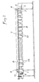
- Two integral carriages 1 and 2 connected by two symmetrical bars 3 can slide freely on two pairs of cylindrical guide rails 4.
- the carriage 1 carries a driving pulley 5 and the carriage 2 a receiving pulley 6 around which can be s 'winding or unwinding a cable 7.
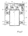
- the ends of the cable 7 are fixed on the manipulator carriage 8 which slides on the guide rail 9 while resting on the fixed beam via rollers 10 (see Figure 2) .
- the two-speed geared motor 11 drives the manipulator carriage 8 via the cable 7, the position of the carriage being given by the encoder 12 connected to the motor 11.
- a pusher constituted by the core of an electro -magnet 14 is housed in a hole 15 provided for this purpose on each tool holder trolley, thus making the two trolleys integral.
- the tool carriage is detached from the manipulator carriage which can then carry out the positioning of another tool carriage.
- all of the tool-carrying carriages 13 can be rigidly connected to each other by a reference synchronization bar 3.
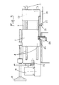
- the position of all the drawing tools can be controlled by the transverse position of the ribbon 20.
- the position of the edge of the ribbon is identified from two cells 21 and 22 which can be moved using an endless screw 23, depending on the gross width of this ribbon.
- This worm is connected to an encoder 24.
- the information of the current position of this edge is transmitted to the geared motor 19 which imperceptibly corrects the position error observed so as not to distort the linearity of the line. This correction is measured by the encoder 25.
Landscapes
- Chemical & Material Sciences (AREA)
- Engineering & Computer Science (AREA)
- Materials Engineering (AREA)
- Organic Chemistry (AREA)
- Re-Forming, After-Treatment, Cutting And Transporting Of Glass Products (AREA)
- Control Of Cutting Processes (AREA)
Applications Claiming Priority (2)
| Application Number | Priority Date | Filing Date | Title |
|---|---|---|---|
| FR8213115A FR2531063A1 (fr) | 1982-07-27 | 1982-07-27 | Dispositifs de commande des elements realisant la decoupe longitudinale d'un ruban de verre en deplacement |
| FR8213115 | 1982-07-27 |
Publications (2)
| Publication Number | Publication Date |
|---|---|
| EP0100277A1 EP0100277A1 (fr) | 1984-02-08 |
| EP0100277B1 true EP0100277B1 (fr) | 1986-10-01 |
Family
ID=9276370
Family Applications (1)
| Application Number | Title | Priority Date | Filing Date |
|---|---|---|---|
| EP19830401505 Expired EP0100277B1 (fr) | 1982-07-27 | 1983-07-22 | Dispositifs de commande des éléments réalisant la découpe longitudinale d'un ruban de verre en déplacement |
Country Status (4)
| Country | Link |
|---|---|
| EP (1) | EP0100277B1 (cg-RX-API-DMAC7.html) |
| DE (1) | DE3366600D1 (cg-RX-API-DMAC7.html) |
| ES (1) | ES8500195A1 (cg-RX-API-DMAC7.html) |
| FR (1) | FR2531063A1 (cg-RX-API-DMAC7.html) |
Families Citing this family (2)
| Publication number | Priority date | Publication date | Assignee | Title |
|---|---|---|---|---|
| DE4113634A1 (de) * | 1991-04-26 | 1992-10-29 | Minnesota Mining & Mfg | Fluoracryl-polymere, verfahren zu ihrer herstellung und ihre anwendung |
| US7359764B2 (en) * | 2005-05-16 | 2008-04-15 | Ppg Industries Ohio, Inc. | On-line/off-line scoring bridge |
Family Cites Families (2)
| Publication number | Priority date | Publication date | Assignee | Title |
|---|---|---|---|---|
| BE698932A (cg-RX-API-DMAC7.html) * | 1967-05-24 | 1967-11-03 | ||
| US4170159A (en) * | 1978-01-03 | 1979-10-09 | Contraves Goerz Corporation | Linear positioning apparatus |
-
1982
- 1982-07-27 FR FR8213115A patent/FR2531063A1/fr active Granted
-
1983
- 1983-07-22 EP EP19830401505 patent/EP0100277B1/fr not_active Expired
- 1983-07-22 DE DE8383401505T patent/DE3366600D1/de not_active Expired
- 1983-07-27 ES ES524488A patent/ES8500195A1/es not_active Expired
Also Published As
| Publication number | Publication date |
|---|---|
| FR2531063A1 (fr) | 1984-02-03 |
| DE3366600D1 (en) | 1986-11-06 |
| ES524488A0 (es) | 1984-10-01 |
| EP0100277A1 (fr) | 1984-02-08 |
| ES8500195A1 (es) | 1984-10-01 |
| FR2531063B1 (cg-RX-API-DMAC7.html) | 1985-02-08 |
Similar Documents
| Publication | Publication Date | Title |
|---|---|---|
| EP0156747B1 (fr) | Procédé et appareil mécanisé pour le découpage de fenêtres carrées ou rectangulaires dans des cadres destinés à l'encadrement artistique | |
| JP5478056B2 (ja) | プラスチックチューブを接合するための装置 | |
| FR2581029A1 (fr) | Distributeur d'etiquettes et machine a affranchir equipee de ce distributeur | |
| EP1450986B1 (fr) | Machine d'usinage pour elements profiles longitudinaux | |
| EP0301989B1 (fr) | Machine à dérouler des bandes comportant des tours porte-bobines | |
| EP0216695B1 (fr) | Procédé et machine pour la fabrication de pièces creuses de revolution formées de fils s'étendant selon trois directions différentes | |
| FR2472918A1 (fr) | Procede et dispositif d'alimentation continue de bande de papier d'une machine de traitement de tabac | |
| EP0100277B1 (fr) | Dispositifs de commande des éléments réalisant la découpe longitudinale d'un ruban de verre en déplacement | |
| EP1820647B1 (fr) | Machine et procédé de marquage de pièces de forme | |
| FR2689807A1 (fr) | Ligne d'usinage de pièces en bois. | |
| CA2012888C (fr) | Positionnement d'une feuille de verre defilant sur un convoyeur | |
| FR2601942A1 (fr) | Appareil pour aligner des feuilles de verre dans une ligne de production, notamment de pare-brise | |
| EP0349438B1 (fr) | Procédé et dispositif d'identification d'outil d'écriture | |
| FR2548169A1 (fr) | Dispositif pour tracer et diviser automatiquement une feuille de verre plat qui peut etre positionne en amont d'une installation de coupe de la feuille | |
| EP0795504A1 (fr) | Machine à dérouler des bobines en continu comportant au moins un moyen de déroulage de deux bobines jumelées ou coaxiales simultanément | |
| CH684217A5 (fr) | Procédé et dispositif pour aligner des fibres optiques. | |
| EP0117231A1 (fr) | Appareil optique de pilotage d'un outil | |
| EP0036374A1 (fr) | Procédé et appareil de soudage avec suivi automatique du joint à souder | |
| JPS58100999A (ja) | 可動保持装置 | |
| EP1809558B1 (fr) | Procede et dispositif de positionnement de bandes et de bobines en vue du raccordement sur une machine a derouler | |
| EP0128811B1 (fr) | Perfectionnements aux dispositifs changeur d'outil pour machine-outil | |
| FR2597390A1 (fr) | Machine pour decouper des feuilles de longueurs variables dans une bande de materiau de support d'impression ou analogue. | |
| FR2526415A1 (fr) | Dispositif de commande simultanee de l'ensemble des outils-traceurs tracant des traits longitudinaux paralleles sur une bande de verre en mouvement | |
| FR2493514A1 (fr) | Dispositif modulaire de controle dimensionnel automatique de pieces de revolution | |
| EP0150150A2 (fr) | Dispositif de mise en application des faces optiques d'au moins une paire de fibres optiques dans un dispositif de raccordement |
Legal Events
| Date | Code | Title | Description |
|---|---|---|---|
| PUAI | Public reference made under article 153(3) epc to a published international application that has entered the european phase |
Free format text: ORIGINAL CODE: 0009012 |
|
| AK | Designated contracting states |
Designated state(s): BE DE GB IT |
|
| 17P | Request for examination filed |
Effective date: 19840723 |
|
| GRAA | (expected) grant |
Free format text: ORIGINAL CODE: 0009210 |
|
| AK | Designated contracting states |
Kind code of ref document: B1 Designated state(s): BE DE GB IT |
|
| ITF | It: translation for a ep patent filed | ||
| REF | Corresponds to: |
Ref document number: 3366600 Country of ref document: DE Date of ref document: 19861106 |
|
| PLBE | No opposition filed within time limit |
Free format text: ORIGINAL CODE: 0009261 |
|
| STAA | Information on the status of an ep patent application or granted ep patent |
Free format text: STATUS: NO OPPOSITION FILED WITHIN TIME LIMIT |
|
| 26N | No opposition filed | ||
| PGFP | Annual fee paid to national office [announced via postgrant information from national office to epo] |
Ref country code: GB Payment date: 19920714 Year of fee payment: 10 |
|
| PGFP | Annual fee paid to national office [announced via postgrant information from national office to epo] |
Ref country code: DE Payment date: 19920722 Year of fee payment: 10 |
|
| ITTA | It: last paid annual fee | ||
| PGFP | Annual fee paid to national office [announced via postgrant information from national office to epo] |
Ref country code: BE Payment date: 19920812 Year of fee payment: 10 |
|
| PG25 | Lapsed in a contracting state [announced via postgrant information from national office to epo] |
Ref country code: GB Effective date: 19930722 |
|
| PG25 | Lapsed in a contracting state [announced via postgrant information from national office to epo] |
Ref country code: BE Effective date: 19930731 |
|
| BERE | Be: lapsed |
Owner name: SOC. GENERALE POUR LES TECHNIQUES NOUVELLES SGN Effective date: 19930731 |
|
| GBPC | Gb: european patent ceased through non-payment of renewal fee |
Effective date: 19930722 |
|
| PG25 | Lapsed in a contracting state [announced via postgrant information from national office to epo] |
Ref country code: DE Effective date: 19940401 |