EP0100277B1 - Apparatus for regulating the cutter heads used in the lengthwise cutting of a moving glass ribbon - Google Patents
Apparatus for regulating the cutter heads used in the lengthwise cutting of a moving glass ribbon Download PDFInfo
- Publication number
- EP0100277B1 EP0100277B1 EP19830401505 EP83401505A EP0100277B1 EP 0100277 B1 EP0100277 B1 EP 0100277B1 EP 19830401505 EP19830401505 EP 19830401505 EP 83401505 A EP83401505 A EP 83401505A EP 0100277 B1 EP0100277 B1 EP 0100277B1
- Authority
- EP
- European Patent Office
- Prior art keywords
- carriage
- tool
- carriages
- holding
- integral
- Prior art date
- Legal status (The legal status is an assumption and is not a legal conclusion. Google has not performed a legal analysis and makes no representation as to the accuracy of the status listed.)
- Expired
Links
Images
Classifications
-
- C—CHEMISTRY; METALLURGY
- C03—GLASS; MINERAL OR SLAG WOOL
- C03B—MANUFACTURE, SHAPING, OR SUPPLEMENTARY PROCESSES
- C03B33/00—Severing cooled glass
- C03B33/02—Cutting or splitting sheet glass or ribbons; Apparatus or machines therefor
- C03B33/023—Cutting or splitting sheet glass or ribbons; Apparatus or machines therefor the sheet or ribbon being in a horizontal position
- C03B33/027—Scoring tool holders; Driving mechanisms therefor
-
- C—CHEMISTRY; METALLURGY
- C03—GLASS; MINERAL OR SLAG WOOL
- C03B—MANUFACTURE, SHAPING, OR SUPPLEMENTARY PROCESSES
- C03B33/00—Severing cooled glass
- C03B33/02—Cutting or splitting sheet glass or ribbons; Apparatus or machines therefor
- C03B33/023—Cutting or splitting sheet glass or ribbons; Apparatus or machines therefor the sheet or ribbon being in a horizontal position
- C03B33/0235—Ribbons
Definitions
- the present invention relates to devices for controlling the elements performing the longitudinal cutting of a moving glass ribbon.
- Glass sheets of different sizes are currently very often directly traced on the glass ribbon produced by the float glass process; this very wide tape runs on the conveyor path at a high speed: the lines perpendicular to the tape are most often drawn at precise intervals using a special machine placed obliquely to the axis of the tape.
- each carriage is composed of a head comprising a cutting element, of a device allowing the lifting or lowering of said head and of devices for controlling these movements of each head.
- the object of the present invention relates to devices making it possible to solve these problems, these devices relating on the one hand to the individual movement of the carriages and, on the other hand, to the movement of all of said carriages.
- a device for individual movement of tool-carrying carriages ensuring the longitudinal cutting of a moving glass ribbon, said carriages being secured to a synchronization bar is known from US-A-4170159.
- said reducing carriage being provided with means making it possible, when said carriage is positioned above a tool carriage, to separate said tool carriage from the synchronization bar (s) with which it is secured, then to drive said tool carriage with it in order to properly position the latter, and finally the means which has produced said separation is released so as to secure said tool carriage with the synchronization bar (s).
- the device relating to a movement of all of the carriages is designed so as to eliminate the deflection phenomenon.
- the means for locating the position of an edge of the strip relative to a cutting device at a given instant may be of any mechanical or optical nature. However, it is preferable to use two optical sensors distant from 2 to 3 millimeters approximately which determine whether the glass ribbon is interposed on the light path emitted by a suitable source and striking said sensors. Obviously, the equilibrium position is achieved when only one of the sensors is reached by a light ray which has not passed through the glass ribbon.
- the locating means When said locating means detects a deviation of the glass ribbon, this detection taking place when the two sensors are struck by light rays of the same nature (that is to say which are either both passed through the glass ribbon glass, ie both passed outside the glass ribbon), the locating means sends a suitable signal to an integrator who will control the controlled simultaneous movement of all of the carriages.
- This movement carried out for example by translation of a synchronization bar of which all the carriages are integral, must take place at a determined maximum speed. This maximum speed is such that at any instant of said displacement the angle made between a theoretical line perpendicular to the direction of movement of the glass ribbon and the cutting line of the carriages is at most equal to a, a being determined in advance .
- said angle a must be very close to a right angle, that is to say that we will tolerate a certain difference (called false squaring) between a and the right angle. It is understood that this maximum possible speed of movement depends on the speed of longitudinal movement of the glass ribbon, that is to say that when the locating means sends a deflection signal, an integrator must, taking into account the speed of movement tape and square tolerances for the cuts made, program the speed of movement of all the carriages.
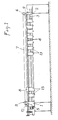
- Two integral carriages 1 and 2 connected by two symmetrical bars 3 can slide freely on two pairs of cylindrical guide rails 4.
- the carriage 1 carries a driving pulley 5 and the carriage 2 a receiving pulley 6 around which can be s 'winding or unwinding a cable 7.
- the ends of the cable 7 are fixed on the manipulator carriage 8 which slides on the guide rail 9 while resting on the fixed beam via rollers 10 (see Figure 2) .
- the two-speed geared motor 11 drives the manipulator carriage 8 via the cable 7, the position of the carriage being given by the encoder 12 connected to the motor 11.
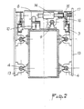
- a pusher constituted by the core of an electro -magnet 14 is housed in a hole 15 provided for this purpose on each tool holder trolley, thus making the two trolleys integral.
- the tool carriage is detached from the manipulator carriage which can then carry out the positioning of another tool carriage.
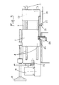
- all of the tool-carrying carriages 13 can be rigidly connected to each other by a reference synchronization bar 3.
- the position of all the drawing tools can be controlled by the transverse position of the ribbon 20.
- the position of the edge of the ribbon is identified from two cells 21 and 22 which can be moved using an endless screw 23, depending on the gross width of this ribbon.
- This worm is connected to an encoder 24.
- the information of the current position of this edge is transmitted to the geared motor 19 which imperceptibly corrects the position error observed so as not to distort the linearity of the line. This correction is measured by the encoder 25.
Description
La présente invention concerne les dispositifs de commande des éléments réalisant le découpage longitudinal d'un ruban de verre en déplacement.The present invention relates to devices for controlling the elements performing the longitudinal cutting of a moving glass ribbon.
Les feuilles de verre de différentes dimensions sont actuellement très souvent directement tracées sur le ruban de verre élaboré par le procédé float glass ; ce ruban de grande largeur défile sur le chemin de convoyage à une vitesse importante : les traits perpendiculaires au ruban sont le plus souvent tracés à intervalles précis à l'aide d'une machine spéciale disposée obliquement par rapport à l'axe du ruban.Glass sheets of different sizes are currently very often directly traced on the glass ribbon produced by the float glass process; this very wide tape runs on the conveyor path at a high speed: the lines perpendicular to the tape are most often drawn at precise intervals using a special machine placed obliquely to the axis of the tape.
Le tracé des traits longitudinaux est réalisé au moyen d'une série de chariots portés par un pont disposé perpendiculairement au sens de déplacement du ruban ; chaque chariot est composé d'une tête comportant un élément coupant, d'un dispositif permettant le relevage ou la descente de ladite tête et de dispositifs de commande de ces mouvements de chaque tête.The layout of the longitudinal lines is carried out by means of a series of carriages carried by a bridge arranged perpendicular to the direction of movement of the ribbon; each carriage is composed of a head comprising a cutting element, of a device allowing the lifting or lowering of said head and of devices for controlling these movements of each head.
Cependant le positionnement de ces chariots le long du pont pose certains problèmes de ce que
- - d'une part, le ruban de verre subit dans le temps des déplacements transversaux (ce phénomène étant connu sous le nom de dérivage)
- - d'autre part, il est nécessaire de pouvoir commander individuellement, et de façon aussi automatique que possible, la position de chaque chariot.
- - on the one hand, the glass ribbon undergoes transverse displacements over time (this phenomenon being known by the name of drift)
- - on the other hand, it is necessary to be able to control individually, and as automatically as possible, the position of each carriage.
Le but de la présente invention concerne des dispositifs permettant de résoudre ces problèmes, ces dispositifs concernant d'une part le déplacement individuel des chariots et, d'autre part, le déplacement de l'ensemble desdits chariots.The object of the present invention relates to devices making it possible to solve these problems, these devices relating on the one hand to the individual movement of the carriages and, on the other hand, to the movement of all of said carriages.
Ainsi il est apparu utile de pouvoir positionner convenablement à chaque instant chacun des chariots de découpe. longitudinale du ruban, le long du pont. Ce positionnement doit se réaliser alors que l'élément coupant du chariot est « relevé •, c'est-à-dire n'est plus en contact avec la surface de verre.Thus it appeared useful to be able to properly position each of the cutting carriages at all times. longitudinal of the ribbon, along the bridge. This positioning must be achieved while the cutting element of the carriage is "raised", that is to say is no longer in contact with the glass surface.
Un dispositif de déplacement individuel de chariots porte-outils assurant la découpe longitudinale d'un ruban de verre en déplacement, lesdits chariots étant solidarisés à une barre de synchronisation est connu du US-A-4170159.A device for individual movement of tool-carrying carriages ensuring the longitudinal cutting of a moving glass ribbon, said carriages being secured to a synchronization bar is known from US-A-4170159.
Ce dispositif est, selon l'invention, caractérisé en ce qu'il comporte :
- - un chariot manipulateur qui coulisse sur un rail de guidage disposé au-dessus des chariots et à distance convenable de ceux-ci
- - et un motoréducteur relié audit chariot manipulateur par un câble sans fin permettant le positionnement exact et un déplacement commandé dudit chariot,
- - a manipulator carriage which slides on a guide rail placed above the carriages and at a suitable distance from them
- - and a gearmotor connected to said manipulator carriage by an endless cable allowing exact positioning and controlled movement of said carriage,
ledit chariot réducteur étant pourvu de moyens permettant, lorsque ledit chariot est positionné au-dessus d'un chariot porte-outil, de désolidariser ledit chariot porte-outil d'avec la (ou les) barre de synchronisation avec laquelle il est solidaire, puis d'entraîner avec lui ledit chariot porte-outil pour positionner convenablement ce dernier, et enfin le moyen ayant réalisé ladite désolidarisa- tion est relâché de façon à solidariser ledit chariot porte-outil avec la (ou les) barre de synchronisation.said reducing carriage being provided with means making it possible, when said carriage is positioned above a tool carriage, to separate said tool carriage from the synchronization bar (s) with which it is secured, then to drive said tool carriage with it in order to properly position the latter, and finally the means which has produced said separation is released so as to secure said tool carriage with the synchronization bar (s).
Le dispositif relatif 'à un mouvement de l'ensemble des chariots est conçu de façon à éliminer le phénomène de dévirage.The device relating to a movement of all of the carriages is designed so as to eliminate the deflection phenomenon.
Dans ce but, le dispositif conforme à la revendication 1 comporte un dispositif assurant le déplacement de l'ensemble de chariots porte-outils munis de dispositifs de déplacement individuels selon la revendication 1, lesdits chariots étant solidarisés entre eux au moyen d'au moins une barre de synchronisation en vue de suivre le dévirage du ruban de verre, le dispositif comportant :
- - un moyen de repérage de la position d'un bord du ruban de verre par rapport à un chariot de découpe appelé chariot solidaire
- - et la commande à partir de l'information donnée par ce moyen de repérage, d'un chariot solidaire qui, agissant sur une barre de synchronisation, provoque le déplacement, dans le sens souhaité, de l'ensemble des chariots, ledit déplacement étant effectué à une vitesse telle que, par rapport à la vitesse de déplacement du verre, le trait de découpe reste dans les limites déterminées pour le faux équerrage.
- a means of locating the position of an edge of the glass ribbon relative to a cutting carriage called an integral carriage
- - And the command from the information given by this locating means, of an integral carriage which, acting on a synchronization bar, causes the displacement, in the desired direction, of all of the carriages, said displacement being carried out at a speed such that, relative to the speed of movement of the glass, the cutting line remains within the limits determined for the false squaring.
Le moyen de repérage de la position d'un bord du ruban par rapport à un dispositif de coupe à un instant donné peut être de nature quelconque mécanique ou optique. On préfère cependant l'utilisation de deux capteurs optiques distants de 2 à 3 millimètres environ qui déterminent si le ruban de verre s'interpose sur le trajet lumineux émis par une source convenable et frappant lesdits capteurs. Bien évidemment, la position d'équilibre se trouve réalisée lorsque l'un seulement des capteurs est atteint par un rayon lumineux n'ayant pas traversé le ruban de verre.The means for locating the position of an edge of the strip relative to a cutting device at a given instant may be of any mechanical or optical nature. However, it is preferable to use two optical sensors distant from 2 to 3 millimeters approximately which determine whether the glass ribbon is interposed on the light path emitted by a suitable source and striking said sensors. Obviously, the equilibrium position is achieved when only one of the sensors is reached by a light ray which has not passed through the glass ribbon.
Lorsque ledit moyen de repérage détecte un dévirage du ruban de verre, cette détection ayant lieu lorsque les deux capteurs sont frappés par des rayons lumineux de même nature (c'est-à-dire qui sont soit tous les deux passés à travers le ruban de verre, soit tous les deux passés en dehors du ruban de verre), le moyen de repérage envoie un signal convenable à un intégrateur qui va commander le déplacement simultané contrôlé de l'ensemble des chariots. Ce déplacement, effectué par exemple par translation d'une barre de synchronisation de laquelle tous les chariots sont solidaires, doit se faire à une vitesse maximale déterminée. Cette vitesse maximale est telle qu'à tout instant dudit déplacement l'angle fait entre une ligne théorique perpendiculaire au sens du déplacement du ruban de verre et la ligne de coupe des chariots est au plus égal à a, a étant déterminé à l'avance. Comme les glaces découpées auront généralement une forme générale rectangulaire, ledit angle a devra être très proche d'un angle droit, c'est-à-dire que l'on tolérera une certaine différence (dite faux équerrage) entre a et l'angle droit. On conçoit que cette vitesse de déplacement maximale possible dépende de la vitesse de déplacement longitudinal du ruban de verre, c'est dire que, lorsque le moyen de repérage enverra un signal de dévirage, un intégrateur devra, en tenant compte de la vitesse de déplacement du ruban et des tolérances de l'équerrage pour les découpes effectuées, programmer la vitesse de déplacement de l'ensemble des chariots.When said locating means detects a deviation of the glass ribbon, this detection taking place when the two sensors are struck by light rays of the same nature (that is to say which are either both passed through the glass ribbon glass, ie both passed outside the glass ribbon), the locating means sends a suitable signal to an integrator who will control the controlled simultaneous movement of all of the carriages. This movement, carried out for example by translation of a synchronization bar of which all the carriages are integral, must take place at a determined maximum speed. This maximum speed is such that at any instant of said displacement the angle made between a theoretical line perpendicular to the direction of movement of the glass ribbon and the cutting line of the carriages is at most equal to a, a being determined in advance . As the cut glass will generally have a generally rectangular shape, said angle a must be very close to a right angle, that is to say that we will tolerate a certain difference (called false squaring) between a and the right angle. It is understood that this maximum possible speed of movement depends on the speed of longitudinal movement of the glass ribbon, that is to say that when the locating means sends a deflection signal, an integrator must, taking into account the speed of movement tape and square tolerances for the cuts made, program the speed of movement of all the carriages.
L'invention sera mieux comprise en se référant aux figures 1, 2 et 3 qui illustrent de façon non limitative une mise en oeuvre de l'invention.
- La figure 1 est une vue en élévation frontale du pont de tracé longitudinal avec représentation du mécanisme de positionnement des outils.
- La figure 2 est une coupe du dispositif de décrochage des porte-outils de la barre de synchronisation.
- La figure 3 est une vue du dispositif de correction de position en fonction des mouvements transversaux de la feuille de verre.
- Figure 1 is a front elevational view of the longitudinal layout bridge with representation of the tool positioning mechanism.
- Figure 2 is a section of the device for detaching the tool holders from the synchronization bar.
- Figure 3 is a view of the position correction device as a function of the transverse movements of the glass sheet.
Sur les différentes figures et dans le texte, les numéros utilisés pour repérer une pièce déterminée sont identiques.In the various figures and in the text, the numbers used to locate a specific part are identical.
On se réfère d'abord à la figure 1.We first refer to Figure 1.
Deux chariots solidaires 1 et 2 reliés par deux barres symétriques 3 (éventuellement une seule) peuvent coulisser librement sur deux paires de rails de guidage cylindriques 4. Le chariot 1 porte une poulie motrice 5 et le chariot 2 une poulie réceptrice 6 autour desquelles peut s'enrouler ou se dérouler un câble 7. Les extrémités du câble 7 sont fixées sur le chariot manipulateur 8 qui coulisse sur le rail de guidage 9 tout en s'appuyant sur la poutre fixe par l'intermédiaire de galets 10 (voir figure 2).Two
Le motoréducteur à deux vitesses 11 entraîne le chariot manipulateur 8 par l'intermédiaire du câble 7, la position du chariot étant donnée par le codeur 12 relié au moteur 11.The two-speed geared
Les chariots porte-outils 13, comme les deux chariots solidaires, coulissent librement dans les rails cylindriques 4. Lorsque le chariot manipulateur est positionné face au chariot porte-outil que l'on veut déplacer, un poussoir constitué par le noyau d'un électro-aimant 14 vient se loger dans un trou 15 prévu à cet effet sur chaque chariot porte-outil, rendant ainsi les deux chariots solidaires. Après déplacement de la valeur adéquate, le chariot porte-outil est décroché du chariot manipulateur qui peut alors effectuer le positionnement d'un autre chariot porte-outil.The tool-carrying
On se réfère plus précisément maintenant à la figure 2 afin de mieux comprendre le mode d'action du dispositif selon l'invention. Il a été précisé plus haut que les deux chariots solidaires 1 et 2 étaient reliés par une ou deux barres de synchronisation 3. Cette barre permet, après positionnement, de relier tous les chariots porte-outils entre eux rigidement, donc de les déplacer simultanément en agissant sur le chariot 1 ou 2. Pour assurer l'accrochage du chariot 13 à ou aux barres de synchronisation 3, un doigt basculeur 16 fixé sur chaque chariot 13 est normalement appliqué fortement sur la barre creuse de synchronisation par l'intermédiaire d'un ressort 17. Lorsque l'on veut déplacer le chariot porte-outil, le noyau de l'électro-aimant 14 décrit au paragraphe précédent vient annuler l'action du ressort, autorisant ainsi le déplacement dudit chariot 13.Reference is now made more precisely to FIG. 2 in order to better understand the mode of action of the device according to the invention. It was specified above that the two
On se réfère maintenant à la figure 3 qui illustre le dispositif utilisé pour corriger le dévirage.We now refer to Figure 3 which illustrates the device used to correct the deflection.
Il a été indiqué plus haut que tous les chariots porte-outils 13 pouvaient être reliés rigidement les uns aux autres par une barre de synchronisation repère 3. En agissant sur le chariot solidaire 1 soit manuellement par l'intermédiaire du volant 18, soit automatiquement par l'intermédiaire du motoréducteur 19, on peut asservir la position de l'ensemble des outils de tracé à la position transversale du ruban 20. La position du bord du ruban est repérée à partir de deux cellules 21 et 22 que l'on peut déplacer à l'aide d'une vis sans fin 23, en fonction de la largeur brute de ce ruban. Cette vis sans fin est reliée à un codeur 24. L'information de la position courante de ce bord est transmise au motoréducteur 19 qui corrige insensiblement l'erreur de position constatée pour ne pas fausser la linéarité du trait. Cette correction est mesurée par le codeur 25.It has been indicated above that all of the tool-carrying
Claims (6)
Applications Claiming Priority (2)
| Application Number | Priority Date | Filing Date | Title |
|---|---|---|---|
| FR8213115A FR2531063A1 (en) | 1982-07-27 | 1982-07-27 | DEVICES FOR CONTROLLING THE ELEMENTS REALIZING THE LONGITUDINAL CUTTING OF A DISPLACED GLASS TAPE |
| FR8213115 | 1982-07-27 |
Publications (2)
| Publication Number | Publication Date |
|---|---|
| EP0100277A1 EP0100277A1 (en) | 1984-02-08 |
| EP0100277B1 true EP0100277B1 (en) | 1986-10-01 |
Family
ID=9276370
Family Applications (1)
| Application Number | Title | Priority Date | Filing Date |
|---|---|---|---|
| EP19830401505 Expired EP0100277B1 (en) | 1982-07-27 | 1983-07-22 | Apparatus for regulating the cutter heads used in the lengthwise cutting of a moving glass ribbon |
Country Status (4)
| Country | Link |
|---|---|
| EP (1) | EP0100277B1 (en) |
| DE (1) | DE3366600D1 (en) |
| ES (1) | ES8500195A1 (en) |
| FR (1) | FR2531063A1 (en) |
Families Citing this family (2)
| Publication number | Priority date | Publication date | Assignee | Title |
|---|---|---|---|---|
| DE4113634A1 (en) * | 1991-04-26 | 1992-10-29 | Minnesota Mining & Mfg | FLUORACRYL POLYMERS, METHOD FOR THEIR PREPARATION AND THEIR USE |
| US7359764B2 (en) * | 2005-05-16 | 2008-04-15 | Ppg Industries Ohio, Inc. | On-line/off-line scoring bridge |
Family Cites Families (2)
| Publication number | Priority date | Publication date | Assignee | Title |
|---|---|---|---|---|
| BE698932A (en) * | 1967-05-24 | 1967-11-03 | ||
| US4170159A (en) * | 1978-01-03 | 1979-10-09 | Contraves Goerz Corporation | Linear positioning apparatus |
-
1982
- 1982-07-27 FR FR8213115A patent/FR2531063A1/en active Granted
-
1983
- 1983-07-22 DE DE8383401505T patent/DE3366600D1/en not_active Expired
- 1983-07-22 EP EP19830401505 patent/EP0100277B1/en not_active Expired
- 1983-07-27 ES ES524488A patent/ES8500195A1/en not_active Expired
Also Published As
| Publication number | Publication date |
|---|---|
| EP0100277A1 (en) | 1984-02-08 |
| ES524488A0 (en) | 1984-10-01 |
| FR2531063A1 (en) | 1984-02-03 |
| DE3366600D1 (en) | 1986-11-06 |
| FR2531063B1 (en) | 1985-02-08 |
| ES8500195A1 (en) | 1984-10-01 |
Similar Documents
| Publication | Publication Date | Title |
|---|---|---|
| EP0156747B1 (en) | Method and apparatus for cutting square or rectangular windows out of mats for making picture frames | |
| JP5478056B2 (en) | Equipment for joining plastic tubes | |
| FR2581029A1 (en) | LABEL DISPENSER AND POSTAGE MACHINE EQUIPPED WITH THE DISPENSER | |
| EP0301989B1 (en) | Web unwinding machine with reel-carrying towers | |
| EP0141717B1 (en) | Positioning device for robots | |
| EP0216695A1 (en) | Method and machine for the manufacture of hollow parts rotationally formed from filaments extending along three different directions | |
| FR2472918A1 (en) | METHOD AND DEVICE FOR CONTINUOUS FEEDING OF PAPER STRIP FROM A TOBACCO TREATMENT MACHINE | |
| EP0100277B1 (en) | Apparatus for regulating the cutter heads used in the lengthwise cutting of a moving glass ribbon | |
| EP1820647B1 (en) | Machine and method for marking hollow components | |
| FR2689807A1 (en) | Production line for wooden work pieces such as beams - uses clawed trolley to measure work piece and convey it to various work stations followed by second trolley to complete mfg. process | |
| FR2601942A1 (en) | APPARATUS FOR ALIGNING GLASS SHEETS IN A PRODUCTION LINE, ESPECIALLY A WINDSHIELD | |
| EP0349438B1 (en) | Method and apparatus for the identification of a writing-tool | |
| CA2012888C (en) | Method and apparatus for positioning glass sheets on a conveyor belt | |
| EP1809558B1 (en) | Method and device for positioning strips and rolls in order to connect same to an unwinding machine | |
| FR2548169A1 (en) | DEVICE FOR AUTOMATICALLY TRACING AND DIVIDING A SHEET OF FLAT GLASS WHICH MAY BE POSITIONED UPSTREAM OF A SHEET CUTTING INSTALLATION | |
| EP0075342A2 (en) | Shiftable printhead | |
| EP0795504A1 (en) | Continuous unwinder for bobbins with at least one means for simultaneously unwinding of two bobbins in twin or co-axial arrangement | |
| CH684217A5 (en) | Method and apparatus for aligning optical fibers. | |
| EP0117231A1 (en) | Optical apparatus for controlling a tool | |
| EP3820265A1 (en) | Method and device for cutting a radial electronic component | |
| EP0036374A1 (en) | Method and device for welding with automatic following of the welding-joint | |
| FR2597390A1 (en) | Machine for cutting out sheets of various lengths from a web of printing support material or the like | |
| FR2526415A1 (en) | DEVICE FOR SIMULTANEOUSLY CONTROLLING THE ASSEMBLY OF PLOTTERS DRAWING PARALLEL LONGITUDINAL LINES ON A MOVING BAND OF GLASS | |
| JPH05232327A (en) | Optical fiber cutting device of fusion splicing machine | |
| EP0226547A2 (en) | Apparatus for controlling a traversing operation |
Legal Events
| Date | Code | Title | Description |
|---|---|---|---|
| PUAI | Public reference made under article 153(3) epc to a published international application that has entered the european phase |
Free format text: ORIGINAL CODE: 0009012 |
|
| AK | Designated contracting states |
Designated state(s): BE DE GB IT |
|
| 17P | Request for examination filed |
Effective date: 19840723 |
|
| GRAA | (expected) grant |
Free format text: ORIGINAL CODE: 0009210 |
|
| AK | Designated contracting states |
Kind code of ref document: B1 Designated state(s): BE DE GB IT |
|
| ITF | It: translation for a ep patent filed |
Owner name: JACOBACCI & PERANI S.P.A. |
|
| REF | Corresponds to: |
Ref document number: 3366600 Country of ref document: DE Date of ref document: 19861106 |
|
| PLBE | No opposition filed within time limit |
Free format text: ORIGINAL CODE: 0009261 |
|
| STAA | Information on the status of an ep patent application or granted ep patent |
Free format text: STATUS: NO OPPOSITION FILED WITHIN TIME LIMIT |
|
| 26N | No opposition filed | ||
| PGFP | Annual fee paid to national office [announced via postgrant information from national office to epo] |
Ref country code: GB Payment date: 19920714 Year of fee payment: 10 |
|
| PGFP | Annual fee paid to national office [announced via postgrant information from national office to epo] |
Ref country code: DE Payment date: 19920722 Year of fee payment: 10 |
|
| ITTA | It: last paid annual fee | ||
| PGFP | Annual fee paid to national office [announced via postgrant information from national office to epo] |
Ref country code: BE Payment date: 19920812 Year of fee payment: 10 |
|
| PG25 | Lapsed in a contracting state [announced via postgrant information from national office to epo] |
Ref country code: GB Effective date: 19930722 |
|
| PG25 | Lapsed in a contracting state [announced via postgrant information from national office to epo] |
Ref country code: BE Effective date: 19930731 |
|
| BERE | Be: lapsed |
Owner name: SOC. GENERALE POUR LES TECHNIQUES NOUVELLES SGN Effective date: 19930731 |
|
| GBPC | Gb: european patent ceased through non-payment of renewal fee |
Effective date: 19930722 |
|
| PG25 | Lapsed in a contracting state [announced via postgrant information from national office to epo] |
Ref country code: DE Effective date: 19940401 |