EP0100271A1 - Simplified construction of tools to widen the use of strip tools in the production of metallic articles in small or intermediate series - Google Patents
Simplified construction of tools to widen the use of strip tools in the production of metallic articles in small or intermediate series Download PDFInfo
- Publication number
- EP0100271A1 EP0100271A1 EP19830401470 EP83401470A EP0100271A1 EP 0100271 A1 EP0100271 A1 EP 0100271A1 EP 19830401470 EP19830401470 EP 19830401470 EP 83401470 A EP83401470 A EP 83401470A EP 0100271 A1 EP0100271 A1 EP 0100271A1
- Authority
- EP
- European Patent Office
- Prior art keywords
- punch
- sole
- tools
- dies
- holders
- Prior art date
- Legal status (The legal status is an assumption and is not a legal conclusion. Google has not performed a legal analysis and makes no representation as to the accuracy of the status listed.)
- Granted
Links
Images

Classifications
-
- B—PERFORMING OPERATIONS; TRANSPORTING
- B21—MECHANICAL METAL-WORKING WITHOUT ESSENTIALLY REMOVING MATERIAL; PUNCHING METAL
- B21D—WORKING OR PROCESSING OF SHEET METAL OR METAL TUBES, RODS OR PROFILES WITHOUT ESSENTIALLY REMOVING MATERIAL; PUNCHING METAL
- B21D37/00—Tools as parts of machines covered by this subclass
- B21D37/02—Die constructions enabling assembly of the die parts in different ways
-
- B—PERFORMING OPERATIONS; TRANSPORTING
- B21—MECHANICAL METAL-WORKING WITHOUT ESSENTIALLY REMOVING MATERIAL; PUNCHING METAL
- B21D—WORKING OR PROCESSING OF SHEET METAL OR METAL TUBES, RODS OR PROFILES WITHOUT ESSENTIALLY REMOVING MATERIAL; PUNCHING METAL
- B21D37/00—Tools as parts of machines covered by this subclass
- B21D37/08—Dies with different parts for several steps in a process
-
- Y—GENERAL TAGGING OF NEW TECHNOLOGICAL DEVELOPMENTS; GENERAL TAGGING OF CROSS-SECTIONAL TECHNOLOGIES SPANNING OVER SEVERAL SECTIONS OF THE IPC; TECHNICAL SUBJECTS COVERED BY FORMER USPC CROSS-REFERENCE ART COLLECTIONS [XRACs] AND DIGESTS
- Y10—TECHNICAL SUBJECTS COVERED BY FORMER USPC
- Y10T—TECHNICAL SUBJECTS COVERED BY FORMER US CLASSIFICATION
- Y10T83/00—Cutting
- Y10T83/869—Means to drive or to guide tool
- Y10T83/8745—Tool and anvil relatively positionable
Definitions
- the present invention relates to an assembly for the implementation of operations, such as cutting, bending, etc. a strip of sheet material, for example a strip of metallic sheet, advancing in successive steps of a particular length to the workpiece, said assembly comprising as many punches as operations to be performed, each punch being mounted in a punch holder opposite a die to form a work station and the various punch holders and dies being mountable respectively in the same sole which can be secured to the upper jaw of a press and in the same frame secured to the lower jaw of said press.
- each tool comprising, in addition to the punch, the punch holder and the die specific to the operation, a specific carcass mounting on the press and at least one pair of guide columns.
- the object of the present invention is to reduce the price of the tooling used for strip manufacturing by not making it more specific to the part manufactured but adaptable to the production of different parts, and thus to allow, on the one hand, substantial savings during the production of large series of parts and, on the other hand, strip production of small and medium series.
- the point of attack of the worked blank may vary to the left or to the right relative to the center of the work station, or there may be several punches per work station.
- the punch holders can be immobilized in the common sole by penetration into suitable openings provided in said sole and blocking by means of punch covers, while the dies are immobilizable in suitable cutouts provided in the common frame, the punch holders, the openings, the punch covers, the dies and the cutouts are all of standard dimensions.
- the assembly according to the invention comprises two categories of constituent elements, namely invariable standardization elements comprising the upper sole, the punch covers, the die holders and the frame, and interchangeable standardized elements comprising the door - punches and dies.
- the invention is also applicable to take-back tools, for example, for bending parts prepared elsewhere.
- the tool comprises a standardized opening sole for the establishment and blocking of a particular punch and a frame with standardized cutout for the establishment and blocking of a particular corresponding matrix.
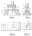
- Figures 3a, 3b, 4a and 4b show the embodiment, also according to the prior art, of a substantially rectangular part extended by two tongues and arched. Again, there is provided a blank cutting tool. (Figure 3a) and a bending tool ( Figure 4b) completely separate from each other and each comprising their own punch cover 1, their own frame 2 and their own ball columns (not shown).
- the tool of FIG. 3a cuts the substantially rectangular part 7 from a blank 6 and the tool of FIG. 3b gives it the desired camber.
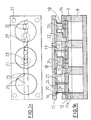
- Figures 5 and 6 which illustrate the invention show that, unlike the prior art, a series of complete and isolated tools is not used for the manufacture of small and medium series, but, as in the conventional tape manufacturing technique, a succession of workstations comprising, in a common structure, only the parts of tools ensuring the expected function.
- the common structure is not specific to a given workpiece but can be used for any parts requiring different advancement steps.
- the assembly according to the invention comprises a lower frame 8, on which is mounted a die holder 9 having several circular cutouts 10 of the same diameter. These cutouts 10 each receive a circular matrix 11 in two parts 11a and 11b. Part 11a of matrix comes to rest on a shoulder 12 defined by the cutout 10 in the die holder 9 and the part llb of matrix, which fits into a cutout 13 provided in an elastic blank press 14, rests on part 11a of matrix , with interposition of the blank 6 to be worked.
- the assembly further comprises an upper sole 15 having as many circular openings 16 of the same diameter as the die holder 9 has cutouts 10, which openings are adapted to receive punch holders 17 facing each other. dies 11. Each punch holder 17 is mounted on a punch cover 18 which is blocked in the upper sole 15 at a shoulder 19 provided in the opening 16.
- the frame 8, the elastic blank presser 14, the upper sole 15 and the punch covers 18 are invariable elements of the structure while the punch holders 17 and the dies 11 are interchangeable .
- the dimensions of the interchangeable elements and the invariable elements are standardized so that it is possible to mount the interchangeable elements at any position in the assembly.
- three work stations are provided which are, from left to right, a drilling station, a pre-diverting station and a bending and separation station.
- the first station comprises two cylindrical punches, the second station a pre-diverting punch 21 and the third posted a bending punch 22 and a separation punch 23.
- 24 pilots to adjust the blank advance 6.
- the method of fixing the punches in the punch holders has not been shown. It can be produced in any suitable manner, in particular by screws and pins.
- FIG. 6 shows, at this 3rd station, the method of fixing the blank press 14 and the matrix 11. It is clear from the comparison between FIGS. 5d and 6d that, in the 2nd work station, the punch 21 does not occupy the same position as the punch 23, this, to adapt the point of attack to the pitch of advancement of the blank and, therefore, to the particular piece.
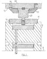
- Figure 7 shows a recovery tool which can be used for the bending of the part 7 as coming from the assembly of Figure 5b.
- the tool is designed according to the same principle as the assemblies in FIGS. 5b and 6b and, here again, the similar parts are designated by the same references.
- the comparison with the isolated bending tool in FIG. 3b clearly shows the difference in design between the known tool and the new tool.
- the invention makes it possible to considerably reduce the cost of the tooling used for the manufacture of large series of parts at the tape and that it allows this band work technique to be used for small and medium series, the price of the tools no longer having to be justified by the large number of parts to be manufactured. Finally, it reduces the risk of work accidents since it replaces, for the modification of the functions of a production line, the displacement of heavy tools by that of small interchangeable parts.
Abstract
L'invention concerne la fabrication à la bande de pièces métalliques. Pour permettre de faire varier le pas et donc de fabriquer des pièces différentes dans la même structure, celle-ci comporte une série de postes de travail (porte-poinçon et matrice) dont les dimensions sont telles qu'elles permettent d'adapter l'écartement des poinçons (20, 21, 22, 23) au pas choisi. Application de la technique de fabrication à la bande aux petites et moyennes séries.The invention relates to the manufacturing of metal parts with a strip. To make it possible to vary the pitch and therefore to make different parts in the same structure, it comprises a series of work stations (punch holder and matrix) whose dimensions are such that they allow the spacing of the punches (20, 21, 22, 23) at the chosen pitch. Application of the tape manufacturing technique to small and medium series.
Description
La présente invention a pour objet un ensemble pour la mise en oeuvre d'opérations, telles que découpage, cambrage, etc. d'une bande de matériau en feuille, par exemple d'une bande de feuille métallique, avançant par pas successifs d'une longueur particulière à la pièce fabriquée, ledit ensemble comprenant autant de poinçons que d'opérations à effectuer, chaque poinçon étant monté dans un porte-poinçon en vis-à-vis d'une matrice pour former un poste de travail et les différents porte-poinçons et matrices étant montables respectivement dans une même semelle solidarisable de la mâchoire supérieure d'une presse et dans un même bâti solidarisable de la mâchoire inférieure de ladite-presse.The present invention relates to an assembly for the implementation of operations, such as cutting, bending, etc. a strip of sheet material, for example a strip of metallic sheet, advancing in successive steps of a particular length to the workpiece, said assembly comprising as many punches as operations to be performed, each punch being mounted in a punch holder opposite a die to form a work station and the various punch holders and dies being mountable respectively in the same sole which can be secured to the upper jaw of a press and in the same frame secured to the lower jaw of said press.
Jusqu'à présent, lorsque l'on désire fabriquer des séries répétitives de pièces à la bande, on fabrique un ensemble spécifique à la pièce en question dans lequel l'écartement entre les postes de travail correspond au pas particulier à cette pièce. Ces ensembles sont coûteux et leur réalisation n'est envisageable que si la série de pièces à fabriquer est suffisamment importante pour permettre l'amortissement du prix des outils.Until now, when it is desired to manufacture repetitive series of parts with a strip, a specific assembly is produced for the part in question in which the spacing between the work stations corresponds to the pitch not particular to this part. These assemblies are expensive and their realization can only be envisaged if the series of parts to be manufactured is large enough to allow the amortization of the price of the tools.
Par conséquent, il n'est pas possible de fabriquer à la bande des séries moyennes (de l'ordre de 6000 pièces par mois) ou petites (de l'ordre de 500 pièces par mois).Consequently, it is not possible to produce medium series (of the order of 6000 pieces per month) or small series (of the order of 500 pieces per month).
Dans le cas de telles séries, on utilise autant d'outils qu'il y a d'opérations à faire, chaque outil comprenant, en plus du poinçon, du porte-poinçon et de la matrice particuliers à l'opération, une carcasse spécifique de montage sur la presse et au moins une paire de colonnes de guidage.In the case of such series, as many tools are used as there are operations to be carried out, each tool comprising, in addition to the punch, the punch holder and the die specific to the operation, a specific carcass mounting on the press and at least one pair of guide columns.
Outre que la fabrication de ces outils individuels est d'un prix de revient élevé, leur utilisation demande du temps et de la main d'oeuvre, la pièce en cours de réalisation devant être présentée successivement à chacun des outils.In addition to the fact that the production of these individual tools is of a high cost price, their use requires time and manpower, the part being produced must be presented successively to each of the tools.
La présente invention a pour but de réduire le prix de l'outillage utilisé pour la fabrication à la bande en ne le rendant plus spécifique à la pièce fabriquée mais adaptable à la réalisation de pièces différentes, et de permettre ainsi, d'une part, une économie substantielle lors de la fabrication de grandes séries de pièces et, d'autre part, une fabrication à la bande de petites et moyennes séries.The object of the present invention is to reduce the price of the tooling used for strip manufacturing by not making it more specific to the part manufactured but adaptable to the production of different parts, and thus to allow, on the one hand, substantial savings during the production of large series of parts and, on the other hand, strip production of small and medium series.
Pour ce faire, elle.propose un ensemble qui comporte une série de postes de travail dont les dimensions sont telles qu'elles permettent d'adapter l'écartement des poinçons au pas d'avancement particulier à la pièce fabriquée.To do this, elle.propose a set which includes a series of workstations whose dimensions are such that they allow to adapt the spacing of the punches to the particular advancement step to the manufactured part.
Autrement dit, selon la pièce fabriquée, le point d'attaque du flan travaillé pourra varier vers la gauche ou vers la droite par rapport au centre du poste de travail, ou il pourra y avoir plusieurs poinçons par poste de travail.In other words, depending on the part manufactured, the point of attack of the worked blank may vary to the left or to the right relative to the center of the work station, or there may be several punches per work station.
On réduit ainsi considérablement le coût de l'investissement, en particulier du fait que, pour une pièce donnée, on n'a à fabriquer que les éléments d'outils venant directement en contact avec la pièce à réaliser, c'est-à-dire les porte-poinçons, les poinçons et les matrices, le reste de la structure étant construit une fois pour toute en fonction de la presse à équiper.This considerably reduces the cost of the investment, in particular because, for a given part, one only has to manufacture the tool elements coming directly into contact with the part to be produced, that is to say say punch holders, punches and dies, the rest of the structure being built once and for all according to the press to be fitted.
Par suite de l'abaissement du coût. de l'outillage, il devient économiquement possible de travailler à la bande sur de petites ou moyennes séries.As a result of the lowering of the cost. tooling, it becomes economically possible to work with the strip on small or medium series.
Dans une forme d'exécution préférée de.l'invention, les porte-poinçons sont immobilisables dans la semelle commune par pénétration dans des ouvertures appropriées prévues dans ladite semelle et blocage au moyen de couvre-poinçons, tandis que les matrices sont immobilisables dans des découpes appropriées prévues dans le bâti commun, les porte-poinçons, les ouvertures, les couvre-poinçons, les matrices et les découpes étant tous de dimensions standard.In a preferred embodiment of the invention, the punch holders can be immobilized in the common sole by penetration into suitable openings provided in said sole and blocking by means of punch covers, while the dies are immobilizable in suitable cutouts provided in the common frame, the punch holders, the openings, the punch covers, the dies and the cutouts are all of standard dimensions.
Grâce à cette standardisation, il est possible de remplacer un porte-poinçon par un autre et une matrice par une autre pour modifier la succession d'opérations effectuées selon. l'invention, en conservant inchangés les autres éléments de l'ensemble.Thanks to this standardization, it is possible to replace a punch holder by another and a die by another to modify the succession of operations carried out according to. the invention, keeping the other elements of the assembly unchanged.
Ainsi, l'ensemble selon l'invention comporte deux catégories d'éléments constitutifs, à savoir des éléments de standardisation invariables comprenant la semelle supérieure, les couvre-poinçons, les porte-matrices et le bâti, et des éléments standardisés interchangeables comprenant les porte-poinçons et les matrices.Thus, the assembly according to the invention comprises two categories of constituent elements, namely invariable standardization elements comprising the upper sole, the punch covers, the die holders and the frame, and interchangeable standardized elements comprising the door - punches and dies.
L'invention est également applicable aux outils de reprise, par exemple, à des fins de cambrage de pièces préparées par ailleurs.The invention is also applicable to take-back tools, for example, for bending parts prepared elsewhere.
Dans ce cas, l'outil comprend une semelle à ouverture standardisée pour la mise en place et le blocage d'un poinçon particulier et un bâti à découpe standardisée pour la mise en place et le blocage d'une matrice particulière correspondante.In this case, the tool comprises a standardized opening sole for the establishment and blocking of a particular punch and a frame with standardized cutout for the establishment and blocking of a particular corresponding matrix.
Le seul remplacement, dans la structure standard, du poinçon et de la matrice permet de modifier à faible coût l'opération mise en oeuvre.The only replacement, in the standard structure, of the punch and of the die makes it possible to modify the operation implemented at low cost.
L'invention sera mieux comprise à la lecture de la description suivante faite en référence aux.dessins annexés dans lesquels :
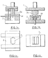
- - les figures la et lb sont des vues en coupe respectivement d'un outil de flan et d'un outil de cambrage, tels qu'utilisés selon l'art antérieur pour la fabrication d'une première pièce en petite pu moyenne série,
- - les figures 2a et 2b sont des vues de dessus du flan tel que travaillé par les outils des figures la et 1b,
- - les figures 3a et 3b sont des vues en coupe respectivement d'un outil de flan et d'un outil de cambrage tels qu'utilisés selon l'art antérieur pour la fabrication d'une deuxième pièce en petite ou moyenne série,
- - les figures 4a et 4b sont des vues de dessus du flan tel que travaillé par les outils des figures 3a et 3b,
- - la figure Sa montre, en vue de dessus, la transformation d'un flan pour la fabrication, selon l'invention, de la première pièce des figures la et lb,
- - la figure 5b montre, en coupe, l'ensemble selon l'invention permettant d'effectuer la succession d'opérations illustrées à la figure 5a,
- - la figure 6a montre, en vue de dessus, la transformation d'un flan pour la fabrication, selon l'invention, de la deuxième pièce des figures 3a et 3b, cette fabrication ayant encore à être achevée par un cambrage,
- - la figure 6b montre, en coupe, l'ensemble selon l'invention permettant d'effectuer la succession d'opéra- tionsillustrées à la figure 6a, et
- - la figure 7 montre, en coupe, un outil standardisé pour opération de reprise.
- FIGS. 1a and 1b are sectional views respectively of a blank tool and of a bending tool, as used according to the prior art for the manufacture of a first part in small or medium series,
- FIGS. 2a and 2b are top views of the blank as worked by the tools of FIGS. 1a and 1b,
- FIGS. 3a and 3b are sectional views respectively of a blank tool and a bending tool as used according to the prior art for the manufacture of a second part in small or medium series,
- FIGS. 4a and 4b are top views of the blank as worked by the tools of FIGS. 3a and 3b,
- - Figure Sa shows, in top view, the transformation of a blank for the manufacture, according to the invention, of the first part of Figures la and lb,
- FIG. 5b shows, in section, the assembly according to the invention making it possible to carry out the succession of operations illustrated in FIG. 5a,
- FIG. 6a shows, in top view, the transformation of a blank for the manufacture, according to the invention, of the second part of FIGS. 3a and 3b, this manufacture still having to be completed by bending,
- FIG. 6b shows, in section, the assembly according to the invention making it possible to carry out the succession of operations illustrated in FIG. 6a, and
- - Figure 7 shows, in section, a standardized tool for recovery operation.
Si l'on se reporte aux figures 1a, 1b, 2a et 2b, on voit la réalisation, selon l'art antérieur, d'une pièce trapézoïdale cambrée par découpage dans un flan (figures la et 2a) et cambrage (figures lb et 2b). Il est prévu deux outils indépendants pour la mise en oeuvre de la fabrication, chacun desdits outils comprenant son propre couvre-poinçon 1 et son propre bâti 2. L'alignement relatif entre les poinçons 3a et 3b et les matrices 4a et 4b est assuré, dans chaque outil, par des colonnes à billes non représentées. L'outil de la figure la découpe la pièce trapézoïdale dans un flan 6 et l'outil de la figure 1b lui donne la cambrure voulue.If we refer to Figures 1a, 1b, 2a and 2b, we see the realization, according to the prior art, of a trapezoidal piece arched by cutting in a blank (Figures la and 2a) and bending (Figures lb and 2b). Two independent tools are provided for carrying out the manufacturing, each of said tools comprising its
Les figures 3a, 3b, 4a et 4b montrent la réalisation, également selon l'art antérieur, d'une pièce sensiblement rectangulaire prolongée par deux languettes et cambrée. Là encore, il est prévu un outil de découpage de flan. (figure 3a) et un outil de cambrage (figure 4b) totalement distincts l'un de l'autre et comprenant chacun leur propre couvre-poinçon 1, leur propre bâti 2 et leurs propres colonnes à billes (non représentées).Figures 3a, 3b, 4a and 4b show the embodiment, also according to the prior art, of a substantially rectangular part extended by two tongues and arched. Again, there is provided a blank cutting tool. (Figure 3a) and a bending tool (Figure 4b) completely separate from each other and each comprising their
L'outil de la figure 3a découpe la pièce sensiblement rectangulaire 7 dans un flan 6 et l'outil de la figure 3b lui donne la cambrure voulue.The tool of FIG. 3a cuts the substantially rectangular part 7 from a blank 6 and the tool of FIG. 3b gives it the desired camber.
Les figures 5 et 6 qui illustrent l'invention montrent qu'à la différence de l'art antérieur, on n'utilise pas, pour la fabrication de petites et moyennes séries, une succession d'outils complets et isolés, mais, comme dans la technique classique de fabrication à la bande, une succession de postes de travail ne comportant, dans une structure commune, que les parties d'outils assurant la fonction attendue.Figures 5 and 6 which illustrate the invention show that, unlike the prior art, a series of complete and isolated tools is not used for the manufacture of small and medium series, but, as in the conventional tape manufacturing technique, a succession of workstations comprising, in a common structure, only the parts of tools ensuring the expected function.
Contrairement à la technique classique, cependant, la structure commune n'est pas spécifique à une pièce à fabriquer donnée mais utilisable pour des pièces quelconques demandant des pas d'avancement différents.Unlike the conventional technique, however, the common structure is not specific to a given workpiece but can be used for any parts requiring different advancement steps.
Si l'on se reporte en particulier aux figures 5b et 6b, on voit que l'ensemble selon l'invention comprend un bâti inférieur 8, sur lequel est monté un porte-matrice 9 présentant plusieurs découpes 10 circulaires de même diamètre. Ces découpes 10 reçoivent chacune une matrice 11 circulaire en deux parties lla et 11b. La partie 11a de matrice vient prendre appui sur un épaulement 12 défini par la découpe 10 dans le porte-matrice 9 et la partie llb de matrice, qui s'encastre dans une découpe 13 prévue dans un presse-flan élastique 14, repose sur la partie 11a de matrice, avec interposition du flan 6 à travailler. L'ensemble comprend, en outre, une semelle supérieure 15 présentant autant d'ouvertures circulaires 16 de même diamètre que le porte-matrice 9 comporte de découpes 10, lesquelles ouvertures sont adaptées à recevoir des porte-poinçons 17 en vis-à-vis des matrices 11. Chaque porte-poinçon 17 est monté sur un couvre-poinçon 18 qui vient se bloquer dans la semelle supérieure 15 au niveau d'un épaulement 19 prévu dans l'ouverture 16.If we refer in particular to Figures 5b and 6b, we see that the assembly according to the invention comprises a
Comme il ressort clairement de la figure Sb, le bâti 8, le presse-flan élastique 14, la semelle supérieure 15 et les couvre-poinçons 18 sont des éléments invariables de la structure tandis que les porte-poinçons 17 et les matrices 11 sont interchangeables. Les dimensions des éléments interchangeables et des éléments invariables sont standardisées de sorte qu'il est possible de monter les éléments interchangeables en n'importe quel poste de l'ensemble.As is clear from FIG. Sb, the
Dans le cas particulier de la figure Sb, il est prévu trois postes de travail qui sont, de gauche à droite, un poste de perçage, un poste de pré-détournage et un poste de cambrage et de séparation.In the particular case of FIG. Sb, three work stations are provided which are, from left to right, a drilling station, a pre-diverting station and a bending and separation station.
Plus précisément, le premier poste comporte deux poinçons cylindriques, le deuxième poste un poinçon de pré-détournage 21 et le troisième posté un poinçon de cambrage 22 et un poinçon de séparation 23. Il est prévu, d'une manière connue en soi, des pilotes 24 pour ajuster l'avance du flan 6.More specifically, the first station comprises two cylindrical punches, the second station a
Il y a en fait un couple de poinçons de chaque type précité par poste de travail pour que chaque opération prépare deux pièces 5 tête bêche, comme cela ressort clairement de la figure Sb. On ne décrira toutefois que la fabrication des pièces 5 dont la grande base est dirigée vers le b_as de la figure. Au premier pas du flan 6, les poinçons 20 percent les trous 25 et au pas suivant les trous 26. Après un certain nombre de pas, le flan 6 atteint le poste de pré-détournage où le poinçon 21 taille les découpes 27 et 28. Après un nouveau nombre de pas, le flan 6 atteint le poste de cambrage et de séparation où le poinçon 22 cambre la pièce 5 selon la ligne 29, après quoi le poinçon de séparation 23 termine le découpage de la pièce en 30. Il est donné aux pièces standardisées interchangeables, et en particulier aux porte-poinçons 17 et aux matrices 11, des dimensions suffisantes pour que l'on puisse faire varier l'écartement entre les poinçons 20,21,22,23 des postes de travail successifs et adapter cet écartement au pas d'avancement du flan.There are in fact a couple of punches of each aforementioned type per work station so that each operation prepares two
Le mode de fixation des poinçons dans les porte-poinçons n'a pas été représenté. Il peut être réalisé de toute manière appropriée, notamment par vis et goupilles.The method of fixing the punches in the punch holders has not been shown. It can be produced in any suitable manner, in particular by screws and pins.
Comme il ressort de la figure Sa, il n'est besoin que de quatre colonnes de guidage à billes 30 pour tout l'ensemble.As can be seen from FIG. Sa, only four
L'ensemble représenté aux figures 6a et 6b comporte la même structure de base que celle représentée aux figures Sa et Sb, et les pièces analogues sont désignées par les mêmes références. On prépare cette fois une pièce 7 par perçage (1er poste) et découpage (2ème poste), le 3ème poste étant laissé vacant. La figure 6 montre, au niveau de ce 3ème poste, le mode de fixation du presse-flan 14 et de la matrice 11. Il ressort clairement de la comparaison entre les figures 5d et 6d que, dans le 2ème poste de travail, le poinçon 21 n'occupe pas la même position que le poinçon 23, ce, pour adapter le point d'attaque au pas d'avancement du flan et, donc, à la pièce particulière.The assembly shown in Figures 6a and 6b has the same basic structure as that shown in Figures Sa and Sb, and similar parts are designated by the same references. This time, a part 7 is prepared by drilling (1st station) and cutting (2nd station), the 3rd station being left vacant. FIG. 6 shows, at this 3rd station, the method of fixing the
La figure 7 montre un outil de reprise qui peut être utilisé pour le cambrage de la pièce 7 telle qu'issue de l'ensemble de la figure 5b. L'outil est conçu selon le même principe que les ensembles des figures 5b et 6b et, là encore, les pièces analogues sont désignées par les mêmes références. La comparaison avec l'outil de cambrage isolé de la figure 3b montre clairement la différence de conception entre l'outil connu et le nouvel outil.Figure 7 shows a recovery tool which can be used for the bending of the part 7 as coming from the assembly of Figure 5b. The tool is designed according to the same principle as the assemblies in FIGS. 5b and 6b and, here again, the similar parts are designated by the same references. The comparison with the isolated bending tool in FIG. 3b clearly shows the difference in design between the known tool and the new tool.
Il ressort de la présente description que l'invention permet de réduire considérablement le coût de l'outillage utilisé pour la fabrication des grandes séries de pièces à la bande et qu'elle permet d'utiliser cette technique de travail à la bande pour de petites et moyennes séries, le prix de l'outillage n'ayant plus besoin d'être justifié par le nombre important de pièces à fabriquer. Enfin, elle réduit les risques d'accidents de travail puisqu'elle remplace, pour la modification des fonctions d'une chaîne de fabrication, le déplacement d'outils pesants par celui de petites pièces interchangeables.It appears from the present description that the invention makes it possible to considerably reduce the cost of the tooling used for the manufacture of large series of parts at the tape and that it allows this band work technique to be used for small and medium series, the price of the tools no longer having to be justified by the large number of parts to be manufactured. Finally, it reduces the risk of work accidents since it replaces, for the modification of the functions of a production line, the displacement of heavy tools by that of small interchangeable parts.
Claims (5)
Applications Claiming Priority (2)
| Application Number | Priority Date | Filing Date | Title |
|---|---|---|---|
| FR8212701 | 1982-07-21 | ||
| FR8212701A FR2530507A1 (en) | 1982-07-21 | 1982-07-21 | SIMPLIFIED CONSTRUCTION OF TOOLS FOR EXTENDING THE USE OF TOOLS TO THE BAND IN THE SMALL AND MEDIUM-SIZED MANUFACTURE OF METALLIC ARTICLES |
Publications (2)
| Publication Number | Publication Date |
|---|---|
| EP0100271A1 true EP0100271A1 (en) | 1984-02-08 |
| EP0100271B1 EP0100271B1 (en) | 1986-10-08 |
Family
ID=9276151
Family Applications (1)
| Application Number | Title | Priority Date | Filing Date |
|---|---|---|---|
| EP19830401470 Expired EP0100271B1 (en) | 1982-07-21 | 1983-07-18 | Simplified construction of tools to widen the use of strip tools in the production of metallic articles in small or intermediate series |
Country Status (4)
| Country | Link |
|---|---|
| US (1) | US4733552A (en) |
| EP (1) | EP0100271B1 (en) |
| DE (1) | DE3366670D1 (en) |
| FR (1) | FR2530507A1 (en) |
Cited By (5)
| Publication number | Priority date | Publication date | Assignee | Title |
|---|---|---|---|---|
| FR2596700A1 (en) * | 1986-04-08 | 1987-10-09 | Esswein Sa | Press tool with modules |
| FR2630939A1 (en) * | 1988-05-09 | 1989-11-10 | Lefils Michel | BAND WORKING TOOL MODULE, SUITABLE FOR WORKING IN THE UNIT OR IN A MULTIMODULAR ASSEMBLY |
| EP0776711A1 (en) * | 1995-11-30 | 1997-06-04 | Denso Corporation | Press working method for plate material and press working apparatus using the same |
| CN106984692A (en) * | 2016-01-20 | 2017-07-28 | 苏州达翔新材料有限公司 | One kind set position die cutting die |
| FR3061864A1 (en) * | 2017-01-19 | 2018-07-20 | Peugeot Citroen Automobiles Sa | MODULABLE PADDING TOOL FOR MANUFACTURING AN OPENING SPRING REINFORCEMENT |
Families Citing this family (18)
| Publication number | Priority date | Publication date | Assignee | Title |
|---|---|---|---|---|
| DE3703649A1 (en) * | 1987-02-06 | 1988-08-18 | Heraeus Gmbh W C | TOOL FOR PUNCHING COMPLEX CUTTING IMAGES FROM A METAL STRIP |
| DE3807075A1 (en) * | 1988-03-04 | 1989-09-14 | Peddinghaus Rolf | TOOL HOLDER FOR A PUNCHING MACHINE |
| DE3838198A1 (en) * | 1988-11-08 | 1990-05-10 | Muhr & Bender | MACHINE TOOL |
| US5007282A (en) * | 1990-01-18 | 1991-04-16 | Amp Incorporated | Stamping and forming machine having interchangeable punch sub-assembly |
| US6061909A (en) * | 1993-07-06 | 2000-05-16 | Ready Metal Manufacturing Co. | Metal panel with flanged holes and process of fabrication |
| US6254542B1 (en) | 1995-07-17 | 2001-07-03 | Intravascular Research Limited | Ultrasonic visualization method and apparatus |
| US6000273A (en) * | 1998-10-21 | 1999-12-14 | Stover; Carl | Press brake punch holder |
| US7314417B2 (en) * | 2000-03-31 | 2008-01-01 | Profil Verbindungstechnik Gmbh & Co. Kg | Method for the manufacture of hollow body elements, hollow body element and also progressive tool for carrying out the method |
| US6645104B2 (en) * | 2000-05-26 | 2003-11-11 | Honda Giken Kogyo Kabushiki Kaisha | Element for belt for continuously variable transmission |
| US6691547B2 (en) * | 2001-12-21 | 2004-02-17 | E & E Manufacturing Company, Inc. | Method of doing business and manufacturing in a stamping and extrusion facility |
| FR2853854B1 (en) * | 2003-04-17 | 2005-06-10 | Gravo Marque Trophees Coupes G | STAMPING, CUTTING AND / OR CRIMPING CHARACTER AND METHOD OF MANUFACTURING THE SAME |
| CA2466688A1 (en) * | 2004-04-30 | 2005-10-30 | Dana Canada Corporation | Apparatus and method for forming shaped articles |
| DE102004035797B9 (en) * | 2004-07-23 | 2006-07-13 | Langenstein & Schemann Gmbh | Method and device for transferring a workpiece |
| US7055353B2 (en) * | 2004-07-28 | 2006-06-06 | Ralph Cowie | Progressive stamping die |
| US20080148802A1 (en) * | 2006-12-21 | 2008-06-26 | Nieschulz Daniel F | Free Part Retrieval System and Method |
| DE102009009169B4 (en) * | 2009-02-16 | 2011-12-01 | Federal-Mogul Sealing Systems Gmbh | Flat gasket with wavy stopper |
| JP6859214B2 (en) * | 2017-06-30 | 2021-04-14 | 日清紡メカトロニクス株式会社 | Drilling equipment for square pipes. |
| CN108817231A (en) * | 2018-08-15 | 2018-11-16 | 天津恒鸿鑫德机械有限公司 | A kind of processing mold with quick disassembling function |
Citations (8)
| Publication number | Priority date | Publication date | Assignee | Title |
|---|---|---|---|---|
| US1402284A (en) * | 1918-05-29 | 1922-01-03 | George H Daniels | Sectional die |
| US1462733A (en) * | 1921-06-20 | 1923-07-24 | Empire Stamping Tool & Mfg Com | Compound progressive punch and dies |
| US1768294A (en) * | 1930-06-24 | of cleveland | ||
| US2989936A (en) * | 1957-06-28 | 1961-06-27 | Torrington Mfg Co | Method for forming end plates and end rings |
| US3060845A (en) * | 1960-05-26 | 1962-10-30 | Western Electric Co | Adjustable embossing punch and die |
| FR2263836A1 (en) * | 1974-03-12 | 1975-10-10 | Gregorovic Dragutin | |
| GB2063137A (en) * | 1979-08-14 | 1981-06-03 | Toyo Seikan Kaisha Ltd | Method and apparatus of feeding material for progressive punching |
| GB2064402A (en) * | 1979-12-10 | 1981-06-17 | Baxendale & Sons Ltd | A Machine Tool |
Family Cites Families (8)
| Publication number | Priority date | Publication date | Assignee | Title |
|---|---|---|---|---|
| US2232071A (en) * | 1940-11-13 | 1941-02-18 | Quality Hardware And Machine C | Method of manufacturing metallic cartridge belt links |
| DE2016458A1 (en) * | 1969-04-16 | 1970-10-29 | Punch and Die Retainers Ltd., London | Compression plate for cutting dies |
| US3983739A (en) * | 1975-06-09 | 1976-10-05 | Dayton Progress Corporation | Work performing member with removable head |
| US4327618A (en) * | 1977-01-31 | 1982-05-04 | Harvey Menard | Apparatus for cutting a strip of material |
| US4160372A (en) * | 1977-11-28 | 1979-07-10 | The Minster Machine Company | Transfer press having quick change die sets |
| US4151736A (en) * | 1978-04-03 | 1979-05-01 | Buhrke Industries, Inc. | Quick-change apparatus for heavy die sets |
| JPS57193243A (en) * | 1981-05-25 | 1982-11-27 | Fujisash Co | Press machine |
| JPS6023050Y2 (en) * | 1981-12-16 | 1985-07-09 | 株式会社小松製作所 | folding machine |
-
1982
- 1982-07-21 FR FR8212701A patent/FR2530507A1/en active Granted
-
1983
- 1983-07-18 DE DE8383401470T patent/DE3366670D1/en not_active Expired
- 1983-07-18 EP EP19830401470 patent/EP0100271B1/en not_active Expired
-
1986
- 1986-03-18 US US06/840,789 patent/US4733552A/en not_active Expired - Fee Related
Patent Citations (8)
| Publication number | Priority date | Publication date | Assignee | Title |
|---|---|---|---|---|
| US1768294A (en) * | 1930-06-24 | of cleveland | ||
| US1402284A (en) * | 1918-05-29 | 1922-01-03 | George H Daniels | Sectional die |
| US1462733A (en) * | 1921-06-20 | 1923-07-24 | Empire Stamping Tool & Mfg Com | Compound progressive punch and dies |
| US2989936A (en) * | 1957-06-28 | 1961-06-27 | Torrington Mfg Co | Method for forming end plates and end rings |
| US3060845A (en) * | 1960-05-26 | 1962-10-30 | Western Electric Co | Adjustable embossing punch and die |
| FR2263836A1 (en) * | 1974-03-12 | 1975-10-10 | Gregorovic Dragutin | |
| GB2063137A (en) * | 1979-08-14 | 1981-06-03 | Toyo Seikan Kaisha Ltd | Method and apparatus of feeding material for progressive punching |
| GB2064402A (en) * | 1979-12-10 | 1981-06-17 | Baxendale & Sons Ltd | A Machine Tool |
Cited By (8)
| Publication number | Priority date | Publication date | Assignee | Title |
|---|---|---|---|---|
| FR2596700A1 (en) * | 1986-04-08 | 1987-10-09 | Esswein Sa | Press tool with modules |
| FR2630939A1 (en) * | 1988-05-09 | 1989-11-10 | Lefils Michel | BAND WORKING TOOL MODULE, SUITABLE FOR WORKING IN THE UNIT OR IN A MULTIMODULAR ASSEMBLY |
| EP0342103A1 (en) * | 1988-05-09 | 1989-11-15 | Lefils, Reine | Strip tool module, adapted to work alone or in combination with other modules |
| EP0776711A1 (en) * | 1995-11-30 | 1997-06-04 | Denso Corporation | Press working method for plate material and press working apparatus using the same |
| US5791186A (en) * | 1995-11-30 | 1998-08-11 | Denso Corporation | Press working method for plate material and press working apparatus using the same |
| CN106984692A (en) * | 2016-01-20 | 2017-07-28 | 苏州达翔新材料有限公司 | One kind set position die cutting die |
| CN106984692B (en) * | 2016-01-20 | 2019-01-25 | 达翔技术(恩施)有限公司 | A kind of set position die cutting die |
| FR3061864A1 (en) * | 2017-01-19 | 2018-07-20 | Peugeot Citroen Automobiles Sa | MODULABLE PADDING TOOL FOR MANUFACTURING AN OPENING SPRING REINFORCEMENT |
Also Published As
| Publication number | Publication date |
|---|---|
| FR2530507B1 (en) | 1985-02-08 |
| FR2530507A1 (en) | 1984-01-27 |
| EP0100271B1 (en) | 1986-10-08 |
| DE3366670D1 (en) | 1986-11-13 |
| US4733552A (en) | 1988-03-29 |
Similar Documents
| Publication | Publication Date | Title |
|---|---|---|
| EP0100271B1 (en) | Simplified construction of tools to widen the use of strip tools in the production of metallic articles in small or intermediate series | |
| EP0136190B1 (en) | Multiple-point welding appliance, especially for vehicle bodies | |
| CA2369598C (en) | Method for holding a part in position in an assembly station | |
| CA2120583C (en) | Portable object and method of fabrication | |
| EP2310153B1 (en) | Method for shaping multiple variants of a sheet metal part and shaping tool and device for implementing said method | |
| EP0200622A1 (en) | Press tool provided with a guiding and ejecting system for the metal strip | |
| FR2763872A1 (en) | METHOD, APPARATUS AND MEMORY FOR FORMING PARTS BY BENDING A METAL SHEET | |
| EP1225658B1 (en) | Crimping tool and device for flexible circuits and crimping station having such a device | |
| FR2982513A1 (en) | Device for shaping and sizing sheet i.e. body side of car, has routing tool for axially deforming portion of sheet, where cutting edge simultaneously prints withdrawal with respect to routing tool for axially releasing routing tool | |
| CA1275012A (en) | Simplified construction of tooling to extend the use of serial tools in the manufacturing process of short and medium runs of metal articles | |
| FR2550110A1 (en) | Screen wiper arm hub part prodn. | |
| FR2712833A1 (en) | Assembly line for automobile bodywork sub-assemblies | |
| EP0904614B1 (en) | Device for crimping of metal lugs in mass production and tool assembly therefor | |
| EP0672479B1 (en) | Punching apparatus for metallic profiles | |
| FR2596700A1 (en) | Press tool with modules | |
| EP2335318B1 (en) | Electrical/mechanical assembly obtained by autogenous riveting | |
| WO2007077325A1 (en) | Method and device for making a part comprising a swaged ring using progressive die stamping | |
| FR3102944A1 (en) | method and device for cutting a radial electronic component | |
| EP0912265B1 (en) | Device for adjusting the size of a machine tool blank holder | |
| FR2745221A1 (en) | SEQUENTIAL CUTTING DEVICE AND METHOD FOR ITS IMPLEMENTATION | |
| CN111885845B (en) | U-shaped groove bonding pad deburring forming method and burr processing improvement process thereof | |
| FR3065659A1 (en) | ADJUSTING APPARATUS AND METHOD OF ADJUSTING THE POSITION OF A PUNCH HOLDER ON A BINDING TOOL. | |
| FR2702685A1 (en) | Device for cutting, trimming and flanging the edges of metal sheets for presses and process for manufacturing it | |
| BE741086A (en) | ||
| FR3057477A1 (en) | CENTERING MATRIX FOR INDUSTRIAL PUNCHING TOOLS |
Legal Events
| Date | Code | Title | Description |
|---|---|---|---|
| PUAI | Public reference made under article 153(3) epc to a published international application that has entered the european phase |
Free format text: ORIGINAL CODE: 0009012 |
|
| AK | Designated contracting states |
Designated state(s): BE CH DE GB IT LI LU NL SE |
|
| 17P | Request for examination filed |
Effective date: 19840725 |
|
| GRAA | (expected) grant |
Free format text: ORIGINAL CODE: 0009210 |
|
| AK | Designated contracting states |
Kind code of ref document: B1 Designated state(s): BE CH DE GB IT LI LU NL SE |
|
| REF | Corresponds to: |
Ref document number: 3366670 Country of ref document: DE Date of ref document: 19861113 |
|
| ITF | It: translation for a ep patent filed |
Owner name: SOCIETA' ITALIANA BREVETTI S.P.A. |
|
| PLBE | No opposition filed within time limit |
Free format text: ORIGINAL CODE: 0009261 |
|
| STAA | Information on the status of an ep patent application or granted ep patent |
Free format text: STATUS: NO OPPOSITION FILED WITHIN TIME LIMIT |
|
| 26N | No opposition filed | ||
| PGFP | Annual fee paid to national office [announced via postgrant information from national office to epo] |
Ref country code: SE Payment date: 19920624 Year of fee payment: 10 |
|
| PGFP | Annual fee paid to national office [announced via postgrant information from national office to epo] |
Ref country code: BE Payment date: 19920630 Year of fee payment: 10 |
|
| PGFP | Annual fee paid to national office [announced via postgrant information from national office to epo] |
Ref country code: LU Payment date: 19920703 Year of fee payment: 10 |
|
| PGFP | Annual fee paid to national office [announced via postgrant information from national office to epo] |
Ref country code: GB Payment date: 19920714 Year of fee payment: 10 |
|
| PGFP | Annual fee paid to national office [announced via postgrant information from national office to epo] |
Ref country code: CH Payment date: 19920728 Year of fee payment: 10 |
|
| ITTA | It: last paid annual fee | ||
| PGFP | Annual fee paid to national office [announced via postgrant information from national office to epo] |
Ref country code: NL Payment date: 19920731 Year of fee payment: 10 |
|
| PGFP | Annual fee paid to national office [announced via postgrant information from national office to epo] |
Ref country code: DE Payment date: 19920828 Year of fee payment: 10 |
|
| EPTA | Lu: last paid annual fee | ||
| PG25 | Lapsed in a contracting state [announced via postgrant information from national office to epo] |
Ref country code: LU Free format text: LAPSE BECAUSE OF NON-PAYMENT OF DUE FEES Effective date: 19930718 Ref country code: GB Effective date: 19930718 |
|
| PG25 | Lapsed in a contracting state [announced via postgrant information from national office to epo] |
Ref country code: SE Effective date: 19930719 |
|
| PG25 | Lapsed in a contracting state [announced via postgrant information from national office to epo] |
Ref country code: LI Effective date: 19930731 Ref country code: CH Effective date: 19930731 Ref country code: BE Effective date: 19930731 |
|
| BERE | Be: lapsed |
Owner name: LEFILS MICHEL Effective date: 19930731 |
|
| PG25 | Lapsed in a contracting state [announced via postgrant information from national office to epo] |
Ref country code: NL Effective date: 19940201 |
|
| GBPC | Gb: european patent ceased through non-payment of renewal fee |
Effective date: 19930718 |
|
| NLV4 | Nl: lapsed or anulled due to non-payment of the annual fee | ||
| REG | Reference to a national code |
Ref country code: CH Ref legal event code: PL |
|
| PG25 | Lapsed in a contracting state [announced via postgrant information from national office to epo] |
Ref country code: DE Effective date: 19940401 |
|
| EUG | Se: european patent has lapsed |
Ref document number: 83401470.6 Effective date: 19940210 |