EP0912265B1 - Device for adjusting the size of a machine tool blank holder - Google Patents
Device for adjusting the size of a machine tool blank holder Download PDFInfo
- Publication number
- EP0912265B1 EP0912265B1 EP97932851A EP97932851A EP0912265B1 EP 0912265 B1 EP0912265 B1 EP 0912265B1 EP 97932851 A EP97932851 A EP 97932851A EP 97932851 A EP97932851 A EP 97932851A EP 0912265 B1 EP0912265 B1 EP 0912265B1
- Authority
- EP
- European Patent Office
- Prior art keywords
- module
- modules
- blank
- holder
- blank holder
- Prior art date
- Legal status (The legal status is an assumption and is not a legal conclusion. Google has not performed a legal analysis and makes no representation as to the accuracy of the status listed.)
- Expired - Lifetime
Links
Images


Classifications
-
- B—PERFORMING OPERATIONS; TRANSPORTING
- B21—MECHANICAL METAL-WORKING WITHOUT ESSENTIALLY REMOVING MATERIAL; PUNCHING METAL
- B21D—WORKING OR PROCESSING OF SHEET METAL OR METAL TUBES, RODS OR PROFILES WITHOUT ESSENTIALLY REMOVING MATERIAL; PUNCHING METAL
- B21D5/00—Bending sheet metal along straight lines, e.g. to form simple curves
- B21D5/04—Bending sheet metal along straight lines, e.g. to form simple curves on brakes making use of clamping means on one side of the work
- B21D5/045—With a wiping movement of the bending blade
-
- B—PERFORMING OPERATIONS; TRANSPORTING
- B21—MECHANICAL METAL-WORKING WITHOUT ESSENTIALLY REMOVING MATERIAL; PUNCHING METAL
- B21D—WORKING OR PROCESSING OF SHEET METAL OR METAL TUBES, RODS OR PROFILES WITHOUT ESSENTIALLY REMOVING MATERIAL; PUNCHING METAL
- B21D5/00—Bending sheet metal along straight lines, e.g. to form simple curves
- B21D5/04—Bending sheet metal along straight lines, e.g. to form simple curves on brakes making use of clamping means on one side of the work
- B21D5/047—Length adjustment of the clamping means
Definitions
- the present invention relates to a device allowing to adapt the size of a blank holder, according to the preamble of claim 1.
- a blank holder is a part of a machine tool intended for the machining of elements in the form of sheets, such as a sheet, allowing good maintenance of the sheet machined.
- a blank holder for example on a bending, stamping or folding machine.
- the size of the blank holder must be adapted to the dimension of the sheet to be machined as well as during the operation performed. In order to be able, on the same machine tool, machine sheets of different sizes, it is necessary to be able to change the size of the blank holder.
- Guide means are provided for the moving the blank holding modules of the second set as well as for the end modules.
- the main drawback of known systems capable of automatically adjusting the size of the hold-down is to perform this operation in a time relatively long, thus limiting productivity by flexibility.
- the time required to machine the sheet is less than the adaptation time of the blank holder by known systems. Therefore, a user seeks to produce several pieces of the same dimension before changing the size of the blank holder.
- the manufacturers recommend carrying out first on the machine tool fitted with a modular blank holder operations requiring a short hold-down, then those requiring a long blank holder. The user is therefore brought to adapt the order of realization of machining according to these constraints.
- the object of the invention is therefore to provide a device for adjusting the size of a blank holder allowing you to change this size very quickly so improve the flexibility of a machine tool intended for receive this blank holder and allow to realize different machining operations in any order, without as much alter the cycle time.
- a change in configuration of the blank holder may then be carried out very quickly. Just move blank holding modules useless for the realization of a predefined folding towards the ends of the guide means and group the blank holding modules necessary for this folding in the center of the guide means and then bringing using the gripping means an end module to each end of the group of hold-down modules for form a blank holder of the desired size to achieve the folding. All these operations can be carried out quickly, because the hold-down modules can move together with the end modules.
- a module called a central module
- the hold-down modules located in the same side of the central module are all alike and the modules blank holder on one side of the central module have a length in the direction of the guide means different from those on the other side of the module central.
- the central module then serves as a stop during moving the blank holder modules.
- the different length hold-down modules on either side of the module central offers a greater variety of different lengths of blank holder. If for example all the blank holder modules and the central module have a length of 100 mm, the assembly formed by the modules hold-down and the central module will always have a length multiple of 100 mm.
- the blank holding modules on one side have a length of 100 mm and those on the other side a length of 50 mm or 150 mm, it will be possible to also have multiple total lengths of 50 mm. Of course other values and other reports in length are possible.
- the guide means consist of at least one rail straight integral with the frame.
- the blank holder modules are mounted on two parallel rails between which a bar is guided drive, and the locking means allow make each blanket module independent of the others either secured to the drive bar, or secured guide rails.
- To move blank holder modules just make them integral with the bar and move it with these modules.
- the other blank holding modules that should not move remain integral with the frame.
- To move all the modules blank holder to be moved just move one times the drive bar in one direction with the modules moving in the same direction and then moving them blank holding modules to be moved in the opposite direction.
- each blank holder module has a piece of lock that can move perpendicular to guide rails, perpendicular to the rails guide a U-shaped section, the end of a branch of the U lying in a longitudinal groove made in a rail, the other end of the branch facing the other guide rail and the drive bar making protruding between these two branches.
- a spring preloads the locking piece in one direction, making it integral with the frame or the bar drive, and finally, a cylinder is provided to act on against the spring in order to make the piece of integral locking of the drive bar or built.
- the training bar To train the training bar, it is fitted with a rack meshing with a toothed wheel driven by a motor.
- a rack meshing with a toothed wheel driven by a motor Other means are of course possible: the bar can for example be connected to a cylinder or to a linear motor.
- the means of gripping and handling can consist of a clamp moving longitudinally on the frame.
- a manipulator robot we may also consider other solutions, such as example a manipulator robot.
- a device according to the invention on a machine intended for make folds on a sheet, comprising two blank clamps and a folding tool. In such a machine, it it is not useful to have two modular blanks, one alone is usually enough.
- Such a machine, or folding machine can adapt the size of the hold-down for the time necessary to let the folded sheet go and a sheet to bend take square.
- a machining center is proposed, characterized in that it comprises two folding machines comprising a device according to the invention, the two machines facing each other, being able to move towards or away from each other, and in that a conveyor intended to convey sheets is placed between the two machines.
- the conveyor can also be fitted with a central rotator, which takes place between the two folding machines, and allows to rotate sheets to be folded on four sides -or more-.
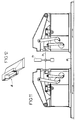
- the Figure 1 shows a machine for bending sheets provided with such a device.
- This machine or folding machine, comprises a bench 2, a brush table 4 intended to receive a sheet (not shown in this figure) to fold, a folding 6, a fixed lower blank holder 8, a blank holder upper 10 mounted on an arm 12 pivoting around a axis 14, as well as a manipulator robot 16 intended for move the sheets to be folded.
- the width of the upper blank holder 10 is modular.
- the folder can adapt to very many sheet sizes and several types of folding.
- the means to modify the size of the hold-down clamps 10 are described below.
- Figures 2 and 3 schematically show the upper blank holder 10 of the folder of FIG. 1 as well that the device for varying the width of this one.
- the blank holder 10 has several blank holder modules 18,19, all of generally similar shape. When all the hold-down modules 18.19 are against each other, they form a hold-down resembling known hold-downs.
- Figures 2 and 3 show a frame 20 carrying two parallel straight rails 22 on which are guided blank holder modules 18, two magazines 24.25, each store being placed at one end of the frame 20, as well as two pieces 26 guided in translation on the frame 20, parallel to the rails 22.
- the 18.19 hold-down modules are of two widths different. In the drawing, the least 18 modules wide are mounted on the left end side of the rails 22, while the widest modules 19 are mounted on the right. So there are two sets of modules hold-down. These two sets are separated by a module central 28 fixed, serving as a stop for the blank holder modules 18.19 mobiles. The general form of this module central 28 is similar to that of the hold-down modules 18.19 mobiles.
- Each mechanism has two pulleys 30, whose axes are perpendicular to the rails 22.
- a belt 32 connects these two pulleys 30.
- a clamp 26 is fixed on the strand upper belt 32 and is guided on the strand inferior.
- An electric motor 34 drives a pulley in rotation. The latter is at the end of the frame 20.
- the other pulley 30 is located substantially central module height 28.
- Each 24.25 store is intended for the storage of end modules 36.37.
- Figure 12 shows one of these end modules.
- each end module can be placed on a corresponding blank holder module.
- the clamps 26 are intended to grip an end module 36,37 stored in its 24.25 store to place it on a blank holder module 18.19, or vice versa, as well as maintaining the module end 36.37 entered in position on the blank holder module 18.19.
- Each clamp 26 can only serve the hold-down modules 18.19 located on the same side of the central module 28.
- the end modules 36 stored in store 24 located on the left in the figures are intended to take place on a blank holder module 18, while the end modules 37 stored in the store 25 located on the right in the figures are intended for take place on a blank holder module 19.
- Each clamp 26 comprises a jack 38.
- a first degree of freedom (belt) allows to move the module end to the corresponding blank holder module and the second degree of freedom (cylinder) allows to fit the end module on the blank holder module.
- Figures 4 to 6 illustrate how can move the blank holder modules 18,19.
- This drive bar 40 is provided of a rack 42 at one of its ends, on which meshes a toothed wheel 44 driven in rotation by a motor (not shown).
- Each 18.19 blank holder module is fitted with a device allowing it either to be integral with the rails 22, or to be integral with the drive bar 40.
- the drive bar 40 moves, it carries with it the hold-down modules 18.19 which are fixed on it, the others remaining motionless. It is so possible to move each blank holder module individually, or a group of hold-down modules, or any other possible combination.
- FIGS 5 and 6 show in section a module blank holder 18 and its associated blocking device. This the latter notably comprises a locking piece 46, a spring 48 and a pneumatic cylinder 50.
- the locking piece 46 is placed in a housing in the face of the blank holder module turned towards the rails 22. This housing is such that the lock can move perpendicular to rails 22.
- the locking piece 46 In a section plane perpendicular to the rails 22 ( Figures 5 and 6), the locking piece 46 has a generally U-shaped section.
- the branches of the U are oriented towards the rails 22.
- the end of a first branch is housed in a groove 52 formed longitudinally in a rail 22.
- the second branch is facing the other guide rail 22.
- the bar drive 40 projects from the two rails 22 and is found between the two branches of the piece of lock 46.
- the second branch of this part 46 makes facing the drive bar 40.
- the piece of locking On the side of its first branch, the piece of locking is subjected to the action of spring 48, which acts in the direction of pushing the first branch of the locking part towards the drive bar 40.
- spring 48 From side of the second branch is the cylinder pneumatic 50. The latter can act on the workpiece lock 46 against spring 48 and therefore push the second branch towards the bar training 40.
- Figure 5 shows the position of the blank holder module 18 when the jack 50 does not act.
- Spring 48 then pushes the locking piece 46 towards the bar 40.
- the first branch of this piece of locking 46 then comes to bear against the wall of the groove 52 formed in a rail 22.
- the blank holder module 18 moves in the opposite direction, that is to say to the left in FIG. 5.
- the module 18 then comes to bear on the outer face of the rail 22 opposite the spring 48.
- the blank holder module is blocked on the two rails 22 and is therefore integral with the frame 20.
- Figure 6 shows the position of the blank holder module 18 when the cylinder 50 acts.
- the cylinder 50 then pushes the locking piece 46 so that its second branch comes to bear against the drive bar 40.
- the blank holder module 18 moves in the opposite direction of movement of the workpiece lock 46, i.e. to the right on the figure 6.
- the dimensions of the various guide grooves for guiding the blank holder module 18 on the rails 22 are such that the blank holder module 18 comes while pressing on the drive bar 40, and not on the rail 22 opposite the pneumatic cylinder 50. In this way, the blank holder module 18 is integral with the bar training 40.
- Figures 7-10 show several possible configurations of blank holder, among many others, obtained by combining modules hold-down clamp 18.19 and end modules 36.37.
- the Figure 7 shows a configuration where all the modules hold-downs 18.19 are grouped around the module central 28 and at each end there is a module end 36.37.
- Figure 8 shows another configuration. For go from the configuration of figure 7 to that of the figure 8, several steps are necessary but they can be done very quickly.
- Modules 36.37 are first replaced in their respective stores.
- the three hold-down modules 18 le further left in Figures 7 and 8 are rendered integral with the drive bar 40. The latter is moved to the left. The pressure in the cylinders 50 corresponding to these three blank holder modules 18 is released. These modules therefore become integral with rails 22 and are fixed relative to the frame 20.
- the three right-hand hold-down modules 19 in FIG. 7 are then made integral with the drive bar 40 by putting the corresponding cylinders 50 under pressure. All the other 18.19 hold-down modules remain integral with the rails 22 and are fixed relative to the frame 20.
- the drive bar 40 moves towards the right, bringing with it the three hold-down modules 19.
- the clamps 26 each grip an end module 36,37 in a corresponding store 24.25 and position it on the module 18.19 forming the end of the blank holder.
- the modules end 36.37 can stay in place and end up between two hold-down modules 18,19, as shown in figure 9. The time required to change configuration can then be slightly reduced.
- Figure 10 shows a configuration where a module end 37 is placed directly on the central module 28. It is thus possible to have a low hold-down width.
- widths of the hold-down modules 18.19 and end modules 36.37 it is possible to cover a whole range of widths for the hold-down obtained with an increment predetermined.
- the example of dimensions indicated below allows obtaining all the multiple widths from 5 mm to from the width of 310 mm.
- modules blank holder 18 with a width of 100 mm which will be on the example shown in the drawing to the left of the module central 28, hold-down modules 19 with a width of 150 mm, which will be to the right of the central module 28, four end modules 36 associated with store 24 and therefore intended to be mounted on hold-down modules 18 of 80 mm, 90 mm, 100 mm and 105 mm, and four modules end 37 associated with the store 25 and therefore intended for be mounted on 19 x 80 mm, 85 mm blank clamp modules, 95 mm and 105 mm.
- the hold-down comprises five hold-down modules 18 of 100 mm and four 150 mm blank holder modules 19, it is possible to assemble the various modules 28,18,19,36,37 to obtain any width of blank holder multiple of 5 mm and between 310 mm and 1310 mm.
- the movement of the clamps 26 and the training bar 40 can be managed with the help of a computer (not shown), which, depending on the width of the blank holder required and the type of fold to carry out, calculate the configuration to be adopted and the course of the various organs then provides this information to a central control system that manages the movement of these organs.
- the design of the modular blank holder such as described above allows you to switch from one configuration to another in a very short time, from the order of ten seconds. It thus becomes possible to change configuration at the same time as you change sheet or position of this sheet. Contrary to machines known so far, which require time about ten times higher, it is possible to change the configuration of the blank holder in masked time.
- a conveyor not shown, provides a sheet 54 between the two folders.
- a central rotator 56 is between the two bending machines to turn a sheet which should optionally be folded on four sides -or more-.
- the two folding machines must be able to move away and get closer to one of the other.
- they are both mounted on a common bench 58.
- a computer and a system of central control can be provided to calculate and manage the movements of the two folders on the bench 58 common, but they can also manage hold-downs modular of the two folders.
- each blank holder module could be equipped with motor means allowing it to move by itself on guide means.
- the training bar would be replaced by a rack fixed extending over the entire length of the frame and each blank holder module would be fitted with an end motor shaft from which a gear would be mounted.
- a brake motor would prevent the gear from rotating, ensuring thus blocking the module relative to the frame.
- the modules could be guided on columns of guidance.
- the device for adapting the size of a hold-down is not necessarily suitable for a folder. he can very well be mounted on any machine with a blank holder, such as a bending machine or stamping.
Abstract
Description
La présente invention a pour objet un dispositif permettant d'adapter la taille d'un serre-flan, selon le préambule de la revendication 1.The present invention relates to a device allowing to adapt the size of a blank holder, according to the preamble of claim 1.
Un serre-flan est une pièce d'une machine-outil destinée à l'usinage d'éléments sous forme de feuilles, tels une tôle, permettant un bon maintien de la feuille usinée. On retrouve un serre-flan par exemple sur une machine de cambrage, d'emboutissage ou de pliage.A blank holder is a part of a machine tool intended for the machining of elements in the form of sheets, such as a sheet, allowing good maintenance of the sheet machined. We find a blank holder for example on a bending, stamping or folding machine.
La taille du serre-flan doit être adaptée à la dimension de la tôle à usiner ainsi qu'à l'opération effectuée. Afin de pouvoir, sur une même machine-outil, usiner des tôles de tailles différentes, il est nécessaire de pouvoir changer la taille du serre-flan.The size of the blank holder must be adapted to the dimension of the sheet to be machined as well as during the operation performed. In order to be able, on the same machine tool, machine sheets of different sizes, it is necessary to be able to change the size of the blank holder.
Il est connu d'adapter l'ensemble du serre-flan,
sans intervention manuelle, à la dimension de la tôle à
usiner. Ainsi, par exemple, le document EP-0 682 996
révèle un dispositif
avec les caractéristiques du préambule de la revendication 1,
permettant d'adapter la taille d'un
serre-flan d'une cintreuse. La largeur totale des
mâchoires est formée par utilisation de modules serre-flan
et de modules d'extrémité de la manière suivante :
Des moyens de guidage sont prévus pour le déplacement des modules serre-flan du deuxième ensemble ainsi que pour les modules d'extrémité.Guide means are provided for the moving the blank holding modules of the second set as well as for the end modules.
Le principal inconvénient des systèmes connus à ce jour et capables d'adapter automatiquement la taille du serre-flan, est d'effectuer cette opération dans un temps relativement long, limitant ainsi la productivité par rapport à la flexibilité. Le temps nécessaire pour usiner la tôle est inférieur au temps d'adaptation du serre-flan par les systèmes connus. De ce fait, un utilisateur recherche à réaliser plusieurs pièces d'une même dimension avant de modifier la taille du serre-flan.The main drawback of known systems capable of automatically adjusting the size of the hold-down, is to perform this operation in a time relatively long, thus limiting productivity by flexibility. The time required to machine the sheet is less than the adaptation time of the blank holder by known systems. Therefore, a user seeks to produce several pieces of the same dimension before changing the size of the blank holder.
De plus, pour des raisons d'optimisation, les constructeurs préconisent de réaliser tout d'abord sur la machine-outil équipée d'un serre-flan modulable les opérations nécessitant un serre-flan court, puis celles nécessitant un serre-flan long. L'utilisateur est donc amené à devoir adapter l'ordre de réalisation des usinages en fonction de ces contraintes.In addition, for reasons of optimization, the manufacturers recommend carrying out first on the machine tool fitted with a modular blank holder operations requiring a short hold-down, then those requiring a long blank holder. The user is therefore brought to adapt the order of realization of machining according to these constraints.
L'invention a alors pour but de fournir un dispositif permettant d'adapter la taille d'un serre-flan permettant de modifier cette taille très rapidement afin d'améliorer la flexibilité d'une machine-outil destinée à recevoir ce serre-flan et de permettre de réaliser les différents usinages dans n'importe quel ordre, sans pour autant altérer le temps de cycle.The object of the invention is therefore to provide a device for adjusting the size of a blank holder allowing you to change this size very quickly so improve the flexibility of a machine tool intended for receive this blank holder and allow to realize different machining operations in any order, without as much alter the cycle time.
A cet effet, le dispositif qu'elle propose comporte :
- un bâti muni de moyens de guidage,
- des modules serre-flan destinés à se déplacer le long des moyens de guidage,
- des moyens pour bloquer indépendamment chaque module serre-flan dans une position donnée, caractérisé en ce qu'il comporte en outre :
- un magasin de modules d'extrémité placé à proximité de chaque extrémité des moyens de guidage,
- des moyens de préhension et de manipulation permettant de saisir un module d'extrémité dans un magasin pour l'emboíter sur un module serre-flan et de retirer un module d'extrémité emboíté sur un module serre-flan pour le replacer dans un magasin.
- a frame provided with guide means,
- blank holding modules intended to move along the guide means,
- means for independently blocking each blank holder module in a given position, characterized in that it further comprises:
- a store of end modules placed near each end of the guide means,
- gripping and handling means making it possible to grasp an end module in a store to nest it on a blank holder module and to remove an end module fitted on a blank holder module to replace it in a store.
Un changement de configuration du serre-flan peut alors être effectué très rapidement. Il suffit de déplacer les modules serre-flan inutiles pour la réalisation d'un pliage prédéfini vers les extrémités des moyens de guidage et de regrouper les modules serre-flan nécessaires à ce pliage au centre des moyens de guidage puis d'apporter à l'aide des moyens de préhension un module d'extrémité à chaque extrémité du groupe de modules serre-flan pour former un serre-flan de la taille souhaitée pour réaliser le pliage. Toutes ces opérations peuvent être réalisée rapidement, car les modules serre-flan peuvent se déplacer en même temps que les modules d'extrémité.A change in configuration of the blank holder may then be carried out very quickly. Just move blank holding modules useless for the realization of a predefined folding towards the ends of the guide means and group the blank holding modules necessary for this folding in the center of the guide means and then bringing using the gripping means an end module to each end of the group of hold-down modules for form a blank holder of the desired size to achieve the folding. All these operations can be carried out quickly, because the hold-down modules can move together with the end modules.
Avantageusement, un module, appelé module central, est monté fixe par rapport au bâti et de chaque côté du module central se trouvent des modules serre-flan mobiles ; les modules serre-flan se trouvant d'un même côté du module central sont tous semblables et les modules serre-flan se trouvant d'un côté du module central présentent une longueur dans le sens des moyens de guidage différente de ceux situés de l'autre côté du module central. Le module central sert alors de butée lors du déplacement des modules serre-flan. La longueur différente des modules serre-flan d'un côté et de l'autre du module central permet d'offrir une plus grande variété de longueurs différentes de serre-flan. Si par exemple tous les modules serre-flan et le module central ont une longueur de 100 mm, l'ensemble formé par les modules serre-flan et le module central aura toujours une longueur multiple de 100 mm. Par contre, si les modules serre-flan d'un côté ont une longueur de 100 mm et ceux de l'autre côté une longueur de 50 mm ou de 150 mm, il sera possible d'avoir également des longueurs totales multiples de 50 mm. Bien entendu d'autres valeurs et d'autres rapport de longueur sont envisageables.Advantageously, a module, called a central module, is mounted fixed with respect to the frame and on each side of the central module are hold-down modules mobile; the hold-down modules located in the same side of the central module are all alike and the modules blank holder on one side of the central module have a length in the direction of the guide means different from those on the other side of the module central. The central module then serves as a stop during moving the blank holder modules. The different length hold-down modules on either side of the module central offers a greater variety of different lengths of blank holder. If for example all the blank holder modules and the central module have a length of 100 mm, the assembly formed by the modules hold-down and the central module will always have a length multiple of 100 mm. On the other hand, if the blank holding modules on one side have a length of 100 mm and those on the other side a length of 50 mm or 150 mm, it will be possible to also have multiple total lengths of 50 mm. Of course other values and other reports in length are possible.
Dans une forme de réalisation préférentielle, les moyens de guidage sont constitués par au moins un rail rectiligne solidaire du bâti. Dans ce cas, avantageusement, les modules serre-flan sont montés sur deux rails parallèles entre lesquels est guidée une barre d'entraínement, et les moyens de blocage permettent de rendre chaque module serre-flan indépendamment des autres soit solidaire de la barre d'entraínement, soit solidaire des rails de guidage. Pour déplacer des modules serre-flan, il suffit de les rendre solidaires de la barre d'entraínement et de déplacer celle-ci avec ces modules. Les autres modules serre-flan ne devant pas bouger restent solidaires du bâti. Pour bouger l'ensemble des modules serre-flan devant être déplacés, il suffit de déplacer une fois la barre d'entraínement dans un sens avec les modules se déplaçant dans ce même sens, puis de déplacer les modules serre-flan devant être déplacés dans l'autre sens.In a preferred embodiment, the guide means consist of at least one rail straight integral with the frame. In that case, advantageously, the blank holder modules are mounted on two parallel rails between which a bar is guided drive, and the locking means allow make each blanket module independent of the others either secured to the drive bar, or secured guide rails. To move blank holder modules, just make them integral with the bar and move it with these modules. The other blank holding modules that should not move remain integral with the frame. To move all the modules blank holder to be moved, just move one times the drive bar in one direction with the modules moving in the same direction and then moving them blank holding modules to be moved in the opposite direction.
Dans une forme de réalisation préférentielle, chaque module serre-flan comporte une pièce de verrouillage pouvant se déplacer perpendiculairement aux rails de guidage, présentant perpendiculairement aux rails de guidage une section en U, l'extrémité d'une branche du U se trouvant dans une rainure longitudinale réalisée dans un rail, l'autre extrémité de branche se trouvant face à l'autre rail de guidage et la barre d'entraínement faisant saillie entre ces deux branches. De plus, un ressort précontraint la pièce de verrouillage dans un sens, rendant celle-ci solidaire du bâti ou de la barre d'entraínement, et enfin, un vérin est prévu pour agir à l'encontre du ressort afin de rendre la pièce de verrouillage solidaire de la barre d'entraínement ou du bâti.In a preferred embodiment, each blank holder module has a piece of lock that can move perpendicular to guide rails, perpendicular to the rails guide a U-shaped section, the end of a branch of the U lying in a longitudinal groove made in a rail, the other end of the branch facing the other guide rail and the drive bar making protruding between these two branches. In addition, a spring preloads the locking piece in one direction, making it integral with the frame or the bar drive, and finally, a cylinder is provided to act on against the spring in order to make the piece of integral locking of the drive bar or built.
Pour entraíner la barre d'entraínement, celle-ci est munie d'une crémaillère engrènant avec une roue dentée entraínée par un moteur. D'autre moyens sont bien entendu envisageables : la barre peut être par exemple reliée à un vérin ou bien à un moteur linéaire.To train the training bar, it is fitted with a rack meshing with a toothed wheel driven by a motor. Other means are of course possible: the bar can for example be connected to a cylinder or to a linear motor.
Dans le dispositif selon l'invention,les moyens de préhension et de manipulation peuvent être constitués par une pince se déplaçant longitudinalement sur le bâti. On peut également envisager d'autres solutions, telles par exemple un robot manipulateur.In the device according to the invention, the means of gripping and handling can consist of a clamp moving longitudinally on the frame. We may also consider other solutions, such as example a manipulator robot.
Il est aussi proposé d'utiliser un dispositif selon l'invention sur une machine destinée à réaliser des plis sur une tôle, comportant deux serre-flans et un outil de pliage. Dans une telle machine, il n'est pas utile d'avoir deux serre-flans modulables, un seul est généralement suffisant.It is also proposed to use a device according to the invention on a machine intended for make folds on a sheet, comprising two blank clamps and a folding tool. In such a machine, it it is not useful to have two modular blanks, one alone is usually enough.
Une telle machine, ou plieuse, peut adapter la taille de son serre-flan pendant le temps nécessaire pour que la tôle pliée parte et qu'une tôle à plier prenne place. Pour des tôles devant être pliées sur deux côtés opposés, il est proposé alors un centre d'usinage, caractérisé en ce qu'il comporte deux plieuses comportant un dispositif selon l'invention, les deux machines se faisant face, pouvant se rapprocher ou s'éloigner l'une de l'autre, et en ce qu'un convoyeur destiné à convoyer des tôles est placé entre les deux machines. Le convoyeur peut être muni aussi d'un rotateur central, qui prend place entre les deux plieuses, et permet de faire tourner des tôles devant être pliées sur quatre côtés -ou plus-.Such a machine, or folding machine, can adapt the size of the hold-down for the time necessary to let the folded sheet go and a sheet to bend take square. For sheets to be folded on two sides opposite, a machining center is proposed, characterized in that it comprises two folding machines comprising a device according to the invention, the two machines facing each other, being able to move towards or away from each other, and in that a conveyor intended to convey sheets is placed between the two machines. The conveyor can also be fitted with a central rotator, which takes place between the two folding machines, and allows to rotate sheets to be folded on four sides -or more-.
De toute façon, l'invention sera bien comprise à
l'aide de la description qui suit, en référence au dessin
schématique annexé représentant, à titre d'exemple,
un dispositif selon un mode de réalisation de l'invention.
A titre d'exemple d'application d'un dispositif permettant d'adapter la taille d'un serre-flan, la figure 1 représente une machine destinée à plier des tôles munie d'un tel dispositif.As an example of application of a device to adapt the size of a blank holder, the Figure 1 shows a machine for bending sheets provided with such a device.
Cette machine, ou plieuse, comporte un banc 2, une
table à brosses 4 destinée à recevoir une tôle (non
représentée sur cette figure) à plier, un outil de
pliage 6, un serre-flan inférieur 8 fixe, un serre-flan
supérieur 10 monté sur un bras 12 pivotant autour d'un
axe 14, ainsi qu'un robot manipulateur 16 destiné à
déplacer les tôles à plier.This machine, or folding machine, comprises a
La largeur du serre-flan supérieur 10 est
modulable. Ainsi, la plieuse peut s'adapter à de très
nombreuses dimensions de tôles et à plusieurs types de
pliage. Les moyens permettant de modifier la taille du
serre-flan 10 sont décrits ci-après.The width of the upper
Les figures 2 et 3 montrent schématiquement le
serre-flan supérieur 10 de la plieuse de la figure 1 ainsi
que le dispositif permettant de faire varier la largeur de
celui-ci.Figures 2 and 3 schematically show the
upper
Le serre-flan 10 comporte plusieurs modules serre-flan
18,19, tous de forme générale semblable. Lorsque tous
les modules serre-flan 18,19 sont l'un contre l'autre, ils
forment un serre-flan ressemblant aux serre-flans connus.The
Les figures 2 et 3 représentent un bâti 20 portant
deux rails 22 rectilignes parallèles sur lesquels sont
guidés les modules serre-flan 18, deux magasins 24,25,
chaque magasin étant placé à une des extrémités du
bâti 20, ainsi que deux pièces 26 guidées en translation
sur le bâti 20, parallèlement aux rails 22.Figures 2 and 3 show a
Les modules serre-flan 18,19 sont de deux largeurs
différentes. Sur le dessin, les modules 18 les moins
larges sont montés du côté de l'extrémité gauche des
rails 22, tandis que les modules 19 les plus larges sont
montés à droite. Il y a donc deux ensembles de modules
serre-flan. Ces deux ensembles sont séparés par un module
central 28 fixe, servant de butée aux modules serre-flan
18,19 mobiles. La forme générale de ce module
central 28 est semblable à celle des modules serre-flan
18,19 mobiles.The 18.19 hold-down modules are of two widths
different. In the drawing, the least 18 modules
wide are mounted on the left end side of the
Sur le bâti 20 sont disposés deux mécanismes pour
l'entraínement en translation des pinces 26. Chaque
mécanisme comporte deux poulies 30, dont les axes sont
perpendiculaires aux rails 22. Une courroie 32 relie ces
deux poulies 30. Une pince 26 est fixée sur le brin
supérieur de la courroie 32 et est guidée sur le brin
inférieur. Un moteur électrique 34 entraíne une poulie en
rotation. Cette dernière se trouve à l'extrémité du
bâti 20. L'autre poulie 30 se trouve sensiblement à
hauteur du module central 28.On the
Chaque magasin 24,25 est destiné au rangement de
modules d'extrémité 36,37. La figure 12 représente l'un de
ces modules d'extrémité. Par complémentarité de forme,
chaque module d'extrémité peut venir se placer sur un
module serre-flan correspondant. Les pinces 26 sont
destinées à saisir un module d'extrémité 36,37 rangé dans
son magasin 24,25 pour le placer sur un module serre-flan
18,19, ou vice versa, ainsi qu'à maintenir le module
d'extrémité 36,37 saisi en position sur le module serre-flan
18,19. Chaque pince 26 ne peut desservir que les
modules serre-flan 18,19 se trouvant d'un même côté du
module central 28. Ainsi, les modules d'extrémité 36
rangés dans le magasin 24 situé à gauche sur les figures
sont destinés à prendre place sur un module serre-flan 18,
tandis que les modules d'extrémité 37 rangés dans le
magasin 25 situé à droite sur les figures sont destinés à
prendre place sur un module serre-flan 19.Each 24.25 store is intended for the storage of
end modules 36.37. Figure 12 shows one of
these end modules. By complementarity of form,
each end module can be placed on a
corresponding blank holder module. The
Chaque pince 26 comprend un vérin 38. Ainsi,
l'extrémité de celle-ci, ainsi que le module d'extrémité
saisi, possèdent deux degrés de liberté. Un premier degré
de liberté (courroie) permet de déplacer le module
d'extrémité jusqu'au module serre-flan correspondant et le
second degré de liberté (vérin) permet d'emboíter le
module d'extrémité sur le module serre-flan.Each
Les figures 4 à 6 illustrent la manière dont
peuvent se déplacer les modules serre-flan 18,19.Figures 4 to 6 illustrate how
can move the
Ces modules sont guidés sur les deux rails
parallèles 22. Entre ces deux rails 22 se trouve un espace
formant une rainure, dans laquelle est guidée une barre
d'entraínement 40. Cette barre d'entraínement 40 est munie
d'une crémaillère 42 à l'une de ses extrémités, sur
laquelle engrène une roue dentée 44 entraínée en rotation
par un moteur (non représenté).These modules are guided on both rails
parallel 22. Between these two
Chaque module serre-flan 18,19 est muni d'un
dispositif lui permettant soit d'être solidaire des rails
22, soit d'être solidaire de la barre d'entraínement 40.
Lorsque la barre d'entraínement 40 se déplace, elle
entraíne avec elle les modules serre-flan 18,19 qui sont
fixés sur elle, les autres restant immobiles. Il est ainsi
possible de déplacer individuellement chaque module serre-flan,
ou un groupe de modules serre-flan, ou tout autre
combinaison envisageable.Each 18.19 blank holder module is fitted with a
device allowing it either to be integral with the
Les figures 5 et 6 montrent en coupe un module
serre-flan 18 et son dispositif de blocage associé. Ce
dernier comprend notamment une pièce de verrouillage 46,
un ressort 48 et un vérin pneumatique 50.Figures 5 and 6 show in section a module
La pièce de verrouillage 46 est placée dans un
logement ménagé dans la face du module serre-flan tournée
vers les rails 22. Ce logement est tel que la pièce de
verrouillage peut se déplacer perpendiculairement aux
rails 22. Dans un plan de coupe perpendiculaire aux
rails 22 (figures 5 et 6), la pièce de verrouillage 46
présente une section de forme générale en U. Les branches
du U sont orientées vers les rails 22. L'extrémité d'une
première branche loge dans une rainure 52 ménagée
longitudinalement dans un rail 22. La seconde branche fait
face à l'autre rail de guidage 22. La barre
d'entraínement 40 fait saillie des deux rails 22 et se
trouve entre les deux branches de la pièce de
verrouillage 46. La seconde branche de cette pièce 46 fait
face à la barre d'entraínement 40.The locking
Du côté de sa première branche, la pièce de
verrouillage est soumise à l'action du ressort 48, qui
agit dans le sens de pousser la première branche de la
pièce de verrouillage vers la barre d'entraínement 40. Du
côté de la seconde branche se trouve le vérin
pneumatique 50. Ce dernier peut agir sur la pièce de
verrouillage 46 à l'encontre du ressort 48 et donc pousser
la seconde branche en direction de la barre
d'entraínement 40.On the side of its first branch, the piece of
locking is subjected to the action of
La figure 5 montre la position du module serre-flan
18 lorsque le vérin 50 n'agit pas. Le ressort 48
pousse alors la pièce de verrouillage 46 vers la barre
d'entraínement 40. La première branche de cette pièce de
verrouillage 46 vient alors en appui contre la paroi de la
rainure 52 ménagée dans un rail 22. Par contre réaction,
le module serre-flan 18 se déplace dans le sens opposé,
c'est-à-dire vers la gauche sur la figure 5. Le module 18
vient alors en appui sur la face extérieure du rail 22
opposée au ressort 48. Ainsi, le module serre-flan est
bloqué sur les deux rails 22 et est donc solidaire du
bâti 20.Figure 5 shows the position of the
La figure 6 montre la position du module serre-flan
18 lorsque le vérin 50 agit. Le vérin 50 pousse alors
la pièce de verrouillage 46 de telle sorte que sa seconde
branche vient en appui contre la barre d'entraínement 40.
Par contre réaction, le module serre-flan 18 se déplace
dans le sens opposé du mouvement de la pièce de
verrouillage 46, c'est-à-dire vers la droite sur la
figure 6. Les cotes des diverses rainures de guidage
permettant le guidage du module serre-flan 18 sur les
rails 22 sont telles que le module serre-flan 18 vient
alors en appui sur la barre d'entraínement 40, et non sur
le rail 22 opposé au vérin pneumatique 50. De cette façon,
le module serre-flan 18 est solidaire de la barre
d'entraínement 40.Figure 6 shows the position of the
Les figures 7 à 10 montrent plusieurs configurations possibles de serre-flan, parmi de nombreuses autres, obtenues en associant des modules serre-flan 18,19 et des modules d'extrémité 36,37. La figure 7 montre une configuration où tous les modules serre-flan 18,19 sont regroupés autour du module central 28 et à chaque extrémité se trouve un module d'extrémité 36,37.Figures 7-10 show several possible configurations of blank holder, among many others, obtained by combining modules hold-down clamp 18.19 and end modules 36.37. The Figure 7 shows a configuration where all the modules hold-downs 18.19 are grouped around the module central 28 and at each end there is a module end 36.37.
La figure 8 montre une autre configuration. Pour
passer de la configuration de la figure 7 à celle de la
figure 8, plusieurs étapes sont nécessaires mais elles
peuvent s'effectuer très rapidement. Les modules
d'extrémité 36,37 sont tout d'abord replacés dans leurs
magasins respectifs. Les trois modules serre-flan 18 le
plus à gauche sur les figures 7 et 8 sont rendus
solidaires de la barre d'entraínement 40. Cette dernière
est déplacée vers la gauche. La pression dans les
vérins 50 correspondant à ces trois modules serre-flan 18
est relâchée. Ces modules deviennent donc solidaires des
rails 22 et sont fixes par rapport au bâti 20. Les trois
modules serre-flan 19 le plus à droite sur la figure 7
sont alors rendus solidaires de la barre d'entraínement 40
en mettant les vérins 50 correspondants sous pression.
Tous les autres modules serre-flan 18,19 restent
solidaires des rails 22 et sont fixes par rapport au
bâti 20. La barre d'entraínement 40 se déplace vers la
droite, entraínant avec elle les trois modules serre-flan
19.Figure 8 shows another configuration. For
go from the configuration of figure 7 to that of the
figure 8, several steps are necessary but they
can be done very quickly. Modules
36.37 are first replaced in their
respective stores. The three hold-down
Pendant que s'effectuent ces déplacements de
modules serre-flan 18,19, les pinces 26 saisissent chacune
un module d'extrémité 36,37 dans un magasin correspondant
24,25 et le positionnent sur le module 18,19 formant
l'extrémité du serre-flan.While these movements are taking place
hold-down modules 18.19, the
Si dans un pliage réalisé ultérieurement par la
plieuse, il n'est pas nécessaire d'avoir un module
d'extrémité à l'extrémité du serre-flan, les modules
d'extrémité 36,37 peuvent rester en place et se retrouver
entre deux modules serre-flan 18,19, comme représenté à la
figure 9. Le temps nécessaire pour changer de
configuration peut alors être légèrement réduit.If in a folding carried out subsequently by the
folder, it is not necessary to have a module
from end to end of the blank holder, the modules
end 36.37 can stay in place and end up
between two hold-down
La figure 10 montre une configuration où un module
d'extrémité 37 est placé directement sur le module central
28. Il est ainsi possible d'avoir un serre-flan de faible
largeur.Figure 10 shows a configuration where a
En choisissant judicieusement les largeurs des modules serre-flan 18,19 et des modules d'extrémité 36,37, il est possible de couvrir toute une plage de largeurs pour le serre-flan obtenu avec une incrémentation prédéterminée. L'exemple de dimensions indiqué ci-après permet d'obtenir toutes les largeurs multiples de 5 mm à partir de la largeur de 310 mm.By judiciously choosing the widths of the hold-down modules 18.19 and end modules 36.37, it is possible to cover a whole range of widths for the hold-down obtained with an increment predetermined. The example of dimensions indicated below allows obtaining all the multiple widths from 5 mm to from the width of 310 mm.
On peut ainsi par exemple choisir des modules
serre-flan 18 d'une largeur de 100 mm, qui se trouveront
sur l'exemple représenté au dessin à gauche du module
central 28, des modules serre-flan 19 d'une largeur de
150 mm, qui seront à droite du module central 28, quatre
modules d'extrémité 36 associés au magasin 24 et donc
destinés à être montés sur des modules serre-flan 18 de
80 mm, 90 mm, 100 mm et 105 mm, et quatre modules
d'extrémité 37 associés au magasin 25 et donc destinés à
être montés sur des modules serre-flan 19 de 80 mm, 85 mm,
95 mm et 105 mm. Si comme représenté aux figures 7 à 10 le
serre-flan comporte cinq modules serre-flan 18 de 100 mm
et quatre modules serre-flan 19 de 150 mm, il est possible
d'assembler les divers modules 28,18,19,36,37 pour obtenir
une quelconque largeur de serre-flan multiple de 5 mm et
comprise entre 310 mm et 1310 mm.We can for example choose modules
Bien entendu, le mouvement des pinces 26 et de la
barre d'entraínement 40 peut être géré avec l'aide d'un
calculateur (non représenté), qui, en fonction de la
largeur du serre-flan nécessaire et le type de pli à
réaliser, calcule la configuration à adopter et les
parcours des divers organes puis fournit ces informations
à un système de commande central qui gère le déplacement
de ces organes.Of course, the movement of the
La conception du serre-flan modulable telle que décrite ci-dessus permet de pouvoir passer d'une configuration à une autre en un temps très réduit, de l'ordre de dix secondes. Il devient ainsi possible de changer de configuration en même temps que l'on change de tôle ou de position de cette tôle. Contrairement aux machines connues jusqu'à présent, qui nécessitent un temps environ dix fois supérieur, il est possible de changer la configuration du serre-flan en temps masqué.The design of the modular blank holder such as described above allows you to switch from one configuration to another in a very short time, from the order of ten seconds. It thus becomes possible to change configuration at the same time as you change sheet or position of this sheet. Contrary to machines known so far, which require time about ten times higher, it is possible to change the configuration of the blank holder in masked time.
Il devient alors concevable de placer deux
plieuses l'une face à l'autre, tel que représenté à la
figure 11. Un convoyeur, non représenté, apporte une
tôle 54 entre les deux plieuses. Un rotateur central 56 se
trouve entre les deux plieuses pour tourner une tôle qui
devrait éventuellement être pliée sur quatre côtés -ou
plus-. Bien sûr, pour s'adapter aux différentes dimensions
de la tôle et au type de pli à réaliser, les deux plieuses
doivent pouvoir s'écarter et se rapprocher l'une de
l'autre. A cet effet, elles sont toutes deux montées sur
un banc 58 commun. Un calculateur et un système de
commande central peuvent être prévus pour calculer et
gérer les déplacements des deux plieuses sur le banc 58
commun, mais ils peuvent aussi gérer les serre-flans
modulables des deux plieuses.It then becomes conceivable to place two
bending machines facing each other, as shown in the
figure 11. A conveyor, not shown, provides a
Comme il va de soi, l'invention ne se limite pas à la forme d'exécution décrite ci-dessus à titre d'exemple ; elle en embrasse au contraire toutes les variantes, qui ne sortent pas du cadre de l'invention telle que revendiquée.It goes without saying that the invention is not limited to the embodiment described above by way of example; on the contrary, it embraces all variants, which do not depart from the scope of the invention as claimed.
Ainsi par exemple, chaque module serre-flan pourrait être équipé de moyens moteurs lui permettant de se déplacer par lui-même sur des moyens de guidage. La barre d'entraínement serait remplacée par une crémaillère fixe s'étendant sur toute la longueur du bâti et chaque module serre-flan serait équipé d'un moteur en bout d'arbre duquel serait monté une roue dentée. Un frein moteur empêcherait la roue dentée de tourner, assurant ainsi le blocage du module par rapport au bâti. Les modules pourraient être guidés sur des colonnes de guidage. So for example, each blank holder module could be equipped with motor means allowing it to move by itself on guide means. The training bar would be replaced by a rack fixed extending over the entire length of the frame and each blank holder module would be fitted with an end motor shaft from which a gear would be mounted. A brake motor would prevent the gear from rotating, ensuring thus blocking the module relative to the frame. The modules could be guided on columns of guidance.
Le dispositif permettant d'adapter la taille d'un serre-flan n'est pas forcément adapté à une plieuse. Il peut très bien être monté sur toute machine comportant un serre-flan, telle une machine de cambrage ou d'emboutissage.The device for adapting the size of a hold-down is not necessarily suitable for a folder. he can very well be mounted on any machine with a blank holder, such as a bending machine or stamping.
La taille, la forme et le nombre des modules ne sont donnés qu'à titre d'exemples pour illustrer l'invention. Il est bien entendu possible de multiplier le nombre de modules pour augmenter le nombre de configurations possibles.The size, shape and number of modules does not are given only as examples to illustrate the invention. It is of course possible to multiply the number of modules to increase the number of possible configurations.
Claims (10)
- Device which makes it possible to adapt the size of a blank holder (10), comprising:characterised in that it additionally comprises:a frame (20) provided with guide means (22);blank-holder modules (18,19) which are designed to be displaced along the guide means;means (46,48,50) for locking each blank-holder module (18,19) independently in a given position,a store (24,25) for end modules (36,37) placed in the vicinity of each end of the guide means; andmeans (26) for grasping and handling, which make it possible to grasp an end module (36,37) in a store (24,25), in order to fit it onto a blank-holder module (18,19) and to remove an end module (36,37) fitted onto a blank-holder module (18,19), in order to place it in a store (24,25) once more.
- Device according to claim 1, characterised in that a module, which is known as the central module (28), is fitted so as to be fixed relative to the frame (20), and in that, on both sides of the central module (28) there are mobile blank-holder modules (18,19), the blank-holder modules which are on a single side of the central module all being similar, and the blank-holder modules on one side of the central module having a length in the direction of the guide means, which is different from that of the modules located on the other side of the central module.
- Device according to claim 1 or claim 2, characterised in that the guide means consist of at least one straight rail (22) which is integral with the frame (20).
- Device according to claim 3, characterised in that the blank-holder modules (18,19) are fitted on two parallel rails (22), between which an entrainment bar (40) is guided, and in that the means (46,48,50) for locking make it possible to render each blank-holder module (18,19) integral, independently from the others, either with the entrainment bar (40), or with the guide rails (22).
- Device according to claim 4, characterised in that each blank-holder module (18,19) comprises a locking part (46), which can be displaced perpendicularly to the guide rails (22), and has a cross-section in the shape of a "U" perpendicular to the guide rails, the end of one branch of the "U" being located in a longitudinal groove (52) provided in one rail (22), the other end of the branch being opposite the other guide rail (22), and the entrainment bar (40) projecting between these two branches, in that a spring (48) prestresses the locking part (46) in one direction, rendering the latter integral with the frame (20) or with the entrainment bar (40), and in that a jack (50) is provided to act against the spring (48), in order to render the locking part (46) integral with the entrainment bar (40) or with the frame (20).
- Device according to claim 4 or claim 5, characterised in that the entrainment bar (40) is provided with a rack (42), which engages with a toothed wheel (44) entrained by a motor.
- Device according to any one of claims 1 to 6, characterised in that the means for grasping and handling consist of a gripper (26), which is displaced longitudinally on the frame (20).
- Machine designed to produce folds on a plate, comprising two blank holders (8,10) and a folding tool (6), characterised in that it comprises a device which makes it possible to adapt the size of a blank holder (10), according to any one of claims 1 to 7.
- Machining centre, characterised in that it comprises two machines according to claim 8, the two machines facing one another, and being able to be moved towards one another or away from one another, and in that a conveyor which is designed to convey plates is placed between the two machines.
- Machining centre according to claim 9, characterised in that it also comprises a central rotation unit (56), which is placed between the two machines designed to produce folds in a plate.
Applications Claiming Priority (3)
| Application Number | Priority Date | Filing Date | Title |
|---|---|---|---|
| FR9608641 | 1996-07-05 | ||
| FR9608641A FR2750626B1 (en) | 1996-07-05 | 1996-07-05 | DEVICE ALLOWING TO ADAPT THE SIZE OF A MACHINE-TOOL CLAMP |
| PCT/FR1997/001227 WO1998001245A1 (en) | 1996-07-05 | 1997-07-07 | Device for adjusting the size of a machine tool blank holder |
Publications (2)
| Publication Number | Publication Date |
|---|---|
| EP0912265A1 EP0912265A1 (en) | 1999-05-06 |
| EP0912265B1 true EP0912265B1 (en) | 2001-01-24 |
Family
ID=9493923
Family Applications (1)
| Application Number | Title | Priority Date | Filing Date |
|---|---|---|---|
| EP97932851A Expired - Lifetime EP0912265B1 (en) | 1996-07-05 | 1997-07-07 | Device for adjusting the size of a machine tool blank holder |
Country Status (7)
| Country | Link |
|---|---|
| US (1) | US6227028B1 (en) |
| EP (1) | EP0912265B1 (en) |
| AT (1) | ATE198845T1 (en) |
| DE (1) | DE69703978T2 (en) |
| ES (1) | ES2155692T3 (en) |
| FR (1) | FR2750626B1 (en) |
| WO (1) | WO1998001245A1 (en) |
Families Citing this family (4)
| Publication number | Priority date | Publication date | Assignee | Title |
|---|---|---|---|---|
| EP2127771B1 (en) | 2008-05-30 | 2012-10-17 | Goiti S. Coop. | Folding machine |
| US8146398B2 (en) * | 2010-08-11 | 2012-04-03 | Cheng Uei Precision Industry Co., Ltd. | Crust bending apparatus |
| AT519221B1 (en) * | 2016-12-06 | 2018-05-15 | Trumpf Maschinen Austria Gmbh & Co Kg | Production plant with a clamping tool and method for adjusting a total length of a bending edge of the clamping tool |
| CN108637100A (en) * | 2018-07-14 | 2018-10-12 | 青岛城之美创意科技股份有限公司 | A kind of omnipotent V-type bending bed die of modularization |
Family Cites Families (9)
| Publication number | Priority date | Publication date | Assignee | Title |
|---|---|---|---|---|
| JPS58148021A (en) * | 1982-02-26 | 1983-09-03 | Hitachi Ltd | Plate bending device |
| JPS5944616U (en) * | 1982-09-08 | 1984-03-24 | 丸機械工業株式会社 | Mold changing device for folding machine |
| US4658625A (en) * | 1984-03-30 | 1987-04-21 | Amada Company, Limited | Bending machine and a die changing system for such bending machine |
| US4722214A (en) * | 1985-03-12 | 1988-02-02 | Murata Kikai Kabushiki Kaisha | Split die for holding work during bending operation |
| AT385688B (en) * | 1986-08-14 | 1988-05-10 | Voest Alpine Ag | DEVICE FOR BENDING SHEET CUTTINGS |
| EP0332221A3 (en) * | 1988-03-11 | 1991-03-13 | Josef Niedermaier | Folding machine |
| US5168745A (en) * | 1989-04-10 | 1992-12-08 | Yamazaki Mazak Kabushiki Kaisha | Die exchange apparatus for the use of a press brake |
| FI96008C (en) * | 1994-02-10 | 1996-04-25 | Balaxman Oy | Method and apparatus of a bending machine |
| DE69429921T2 (en) * | 1994-11-24 | 2002-08-22 | Amada Co | Workpiece press device for variable assembly with predetermined steps for press brakes |
-
1996
- 1996-07-05 FR FR9608641A patent/FR2750626B1/en not_active Expired - Fee Related
-
1997
- 1997-07-07 US US09/214,487 patent/US6227028B1/en not_active Expired - Fee Related
- 1997-07-07 WO PCT/FR1997/001227 patent/WO1998001245A1/en active IP Right Grant
- 1997-07-07 DE DE69703978T patent/DE69703978T2/en not_active Expired - Fee Related
- 1997-07-07 AT AT97932851T patent/ATE198845T1/en not_active IP Right Cessation
- 1997-07-07 EP EP97932851A patent/EP0912265B1/en not_active Expired - Lifetime
- 1997-07-07 ES ES97932851T patent/ES2155692T3/en not_active Expired - Lifetime
Also Published As
| Publication number | Publication date |
|---|---|
| DE69703978T2 (en) | 2001-05-10 |
| EP0912265A1 (en) | 1999-05-06 |
| ES2155692T3 (en) | 2001-05-16 |
| US6227028B1 (en) | 2001-05-08 |
| DE69703978D1 (en) | 2001-03-01 |
| FR2750626A1 (en) | 1998-01-09 |
| FR2750626B1 (en) | 1999-01-29 |
| WO1998001245A1 (en) | 1998-01-15 |
| ATE198845T1 (en) | 2001-02-15 |
Similar Documents
| Publication | Publication Date | Title |
|---|---|---|
| EP0069661B1 (en) | Automatic sheet folding machine | |
| EP0445044B1 (en) | Bending machine with two bending heads | |
| EP1731277A1 (en) | Processing station for a machine for the manufacture of packaging | |
| EP0539254A1 (en) | Modular production line for cardboard boxes | |
| FR2692875A1 (en) | Folding apparatus for producing folded copies from a printed paper web. | |
| EP0912265B1 (en) | Device for adjusting the size of a machine tool blank holder | |
| WO1985001898A1 (en) | Improved automatic machine to camber with a spatial configuration thin and rectilinear elements, particularly metal wires | |
| EP1151833B1 (en) | Apparatus for positioning sheets in a machine station | |
| EP0443395B1 (en) | Apparatus to press and cut longitudinally a moving strip of material | |
| EP0451568A1 (en) | Apparatus to work plate or sheet elements, equipped with a front waste removing device, to produce packings | |
| WO2001026867A1 (en) | Automatic machine for assembling frames | |
| EP0589771A1 (en) | Chip cards manufacturing device | |
| FR2905622A1 (en) | Mechanical manipulator for part assembling and/or controlling machine, has cylinders one of which has shaft connected with plate, and free end, where cylinders have input shafts simultaneously driven in rotation by single driving belt | |
| EP0453984A2 (en) | Device for jogging sheets | |
| EP3820265A1 (en) | Method and device for cutting a radial electronic component | |
| FR2796000A1 (en) | Machine for embossing plastic cards carrying a magnetic strip, integrated circuit or laser recognition patterns, allowing more symbols at higher throughput | |
| WO1998001244A1 (en) | Device for moving part of a machine and for exerting a force at the end of its stroke | |
| EP1011918B1 (en) | Machine-tool assembly for substantially simultaneous machining of a sheet metal | |
| EP1369606A1 (en) | Marking device with at least one guiding member and at least one drive slide | |
| BE1009088A5 (en) | Process for veneers guidance. | |
| CH672444A5 (en) | ||
| FR2746682A1 (en) | Wire=bending machine | |
| FR2696961A1 (en) | Method and apparatus for turning a concave cut in a workpiece, such as a flexible connection plug and flexible connection obtained by this method. | |
| EP1522512B1 (en) | Working station in a machine transforming plate-like elements | |
| EP0236213A1 (en) | Automatic process for making coils without supporting frame and for mounting them on a printed circuit, and machine for carrying out the process |
Legal Events
| Date | Code | Title | Description |
|---|---|---|---|
| PUAI | Public reference made under article 153(3) epc to a published international application that has entered the european phase |
Free format text: ORIGINAL CODE: 0009012 |
|
| 17P | Request for examination filed |
Effective date: 19990125 |
|
| AK | Designated contracting states |
Kind code of ref document: A1 Designated state(s): AT BE CH DE ES FI FR GB IT LI NL SE |
|
| 17Q | First examination report despatched |
Effective date: 19990507 |
|
| RBV | Designated contracting states (corrected) |
Designated state(s): AT BE CH DE ES FI FR GB IE IT LI NL |
|
| RBV | Designated contracting states (corrected) |
Designated state(s): AT BE CH DE ES FI FR GB IT LI NL SE |
|
| GRAG | Despatch of communication of intention to grant |
Free format text: ORIGINAL CODE: EPIDOS AGRA |
|
| GRAG | Despatch of communication of intention to grant |
Free format text: ORIGINAL CODE: EPIDOS AGRA |
|
| GRAH | Despatch of communication of intention to grant a patent |
Free format text: ORIGINAL CODE: EPIDOS IGRA |
|
| GRAH | Despatch of communication of intention to grant a patent |
Free format text: ORIGINAL CODE: EPIDOS IGRA |
|
| GRAA | (expected) grant |
Free format text: ORIGINAL CODE: 0009210 |
|
| AK | Designated contracting states |
Kind code of ref document: B1 Designated state(s): AT BE CH DE ES FI FR GB IT LI NL SE |
|
| PG25 | Lapsed in a contracting state [announced via postgrant information from national office to epo] |
Ref country code: SE Free format text: THE PATENT HAS BEEN ANNULLED BY A DECISION OF A NATIONAL AUTHORITY Effective date: 20010124 Ref country code: NL Free format text: LAPSE BECAUSE OF FAILURE TO SUBMIT A TRANSLATION OF THE DESCRIPTION OR TO PAY THE FEE WITHIN THE PRESCRIBED TIME-LIMIT Effective date: 20010124 Ref country code: FI Free format text: LAPSE BECAUSE OF FAILURE TO SUBMIT A TRANSLATION OF THE DESCRIPTION OR TO PAY THE FEE WITHIN THE PRESCRIBED TIME-LIMIT Effective date: 20010124 Ref country code: AT Free format text: LAPSE BECAUSE OF FAILURE TO SUBMIT A TRANSLATION OF THE DESCRIPTION OR TO PAY THE FEE WITHIN THE PRESCRIBED TIME-LIMIT Effective date: 20010124 |
|
| REF | Corresponds to: |
Ref document number: 198845 Country of ref document: AT Date of ref document: 20010215 Kind code of ref document: T |
|
| REG | Reference to a national code |
Ref country code: CH Ref legal event code: EP |
|
| GBT | Gb: translation of ep patent filed (gb section 77(6)(a)/1977) |
Effective date: 20010124 |
|
| REF | Corresponds to: |
Ref document number: 69703978 Country of ref document: DE Date of ref document: 20010301 |
|
| ITF | It: translation for a ep patent filed |
Owner name: BARZANO' E ZANARDO MILANO S.P.A. |
|
| REG | Reference to a national code |
Ref country code: ES Ref legal event code: FG2A Ref document number: 2155692 Country of ref document: ES Kind code of ref document: T3 |
|
| NLV1 | Nl: lapsed or annulled due to failure to fulfill the requirements of art. 29p and 29m of the patents act | ||
| PGFP | Annual fee paid to national office [announced via postgrant information from national office to epo] |
Ref country code: ES Payment date: 20010710 Year of fee payment: 5 |
|
| PGFP | Annual fee paid to national office [announced via postgrant information from national office to epo] |
Ref country code: GB Payment date: 20010713 Year of fee payment: 5 Ref country code: DE Payment date: 20010713 Year of fee payment: 5 |
|
| PG25 | Lapsed in a contracting state [announced via postgrant information from national office to epo] |
Ref country code: LI Free format text: LAPSE BECAUSE OF NON-PAYMENT OF DUE FEES Effective date: 20010731 Ref country code: CH Free format text: LAPSE BECAUSE OF NON-PAYMENT OF DUE FEES Effective date: 20010731 |
|
| PGFP | Annual fee paid to national office [announced via postgrant information from national office to epo] |
Ref country code: BE Payment date: 20010808 Year of fee payment: 5 |
|
| PLBE | No opposition filed within time limit |
Free format text: ORIGINAL CODE: 0009261 |
|
| STAA | Information on the status of an ep patent application or granted ep patent |
Free format text: STATUS: NO OPPOSITION FILED WITHIN TIME LIMIT |
|
| REG | Reference to a national code |
Ref country code: GB Ref legal event code: IF02 |
|
| 26N | No opposition filed | ||
| REG | Reference to a national code |
Ref country code: CH Ref legal event code: PL |
|
| PG25 | Lapsed in a contracting state [announced via postgrant information from national office to epo] |
Ref country code: FR Free format text: LAPSE BECAUSE OF NON-PAYMENT OF DUE FEES Effective date: 20020329 |
|
| REG | Reference to a national code |
Ref country code: FR Ref legal event code: ST |
|
| PG25 | Lapsed in a contracting state [announced via postgrant information from national office to epo] |
Ref country code: GB Free format text: LAPSE BECAUSE OF NON-PAYMENT OF DUE FEES Effective date: 20020707 |
|
| PG25 | Lapsed in a contracting state [announced via postgrant information from national office to epo] |
Ref country code: ES Free format text: LAPSE BECAUSE OF NON-PAYMENT OF DUE FEES Effective date: 20020708 |
|
| PG25 | Lapsed in a contracting state [announced via postgrant information from national office to epo] |
Ref country code: BE Free format text: LAPSE BECAUSE OF NON-PAYMENT OF DUE FEES Effective date: 20020731 |
|
| BERE | Be: lapsed |
Owner name: *JEANDEAUD JEAN-CLAUDE Effective date: 20020731 |
|
| PG25 | Lapsed in a contracting state [announced via postgrant information from national office to epo] |
Ref country code: DE Free format text: LAPSE BECAUSE OF NON-PAYMENT OF DUE FEES Effective date: 20030201 |
|
| GBPC | Gb: european patent ceased through non-payment of renewal fee |
Effective date: 20020707 |
|
| REG | Reference to a national code |
Ref country code: ES Ref legal event code: FD2A Effective date: 20030811 |
|
| PG25 | Lapsed in a contracting state [announced via postgrant information from national office to epo] |
Ref country code: IT Free format text: LAPSE BECAUSE OF NON-PAYMENT OF DUE FEES;WARNING: LAPSES OF ITALIAN PATENTS WITH EFFECTIVE DATE BEFORE 2007 MAY HAVE OCCURRED AT ANY TIME BEFORE 2007. THE CORRECT EFFECTIVE DATE MAY BE DIFFERENT FROM THE ONE RECORDED. Effective date: 20050707 |