EP1011918B1 - Machine-tool assembly for substantially simultaneous machining of a sheet metal - Google Patents
Machine-tool assembly for substantially simultaneous machining of a sheet metal Download PDFInfo
- Publication number
- EP1011918B1 EP1011918B1 EP98936468A EP98936468A EP1011918B1 EP 1011918 B1 EP1011918 B1 EP 1011918B1 EP 98936468 A EP98936468 A EP 98936468A EP 98936468 A EP98936468 A EP 98936468A EP 1011918 B1 EP1011918 B1 EP 1011918B1
- Authority
- EP
- European Patent Office
- Prior art keywords
- machine tools
- machine
- conveying
- series according
- carriage
- Prior art date
- Legal status (The legal status is an assumption and is not a legal conclusion. Google has not performed a legal analysis and makes no representation as to the accuracy of the status listed.)
- Expired - Lifetime
Links
Images


Classifications
-
- B—PERFORMING OPERATIONS; TRANSPORTING
- B23—MACHINE TOOLS; METAL-WORKING NOT OTHERWISE PROVIDED FOR
- B23Q—DETAILS, COMPONENTS, OR ACCESSORIES FOR MACHINE TOOLS, e.g. ARRANGEMENTS FOR COPYING OR CONTROLLING; MACHINE TOOLS IN GENERAL CHARACTERISED BY THE CONSTRUCTION OF PARTICULAR DETAILS OR COMPONENTS; COMBINATIONS OR ASSOCIATIONS OF METAL-WORKING MACHINES, NOT DIRECTED TO A PARTICULAR RESULT
- B23Q39/00—Metal-working machines incorporating a plurality of sub-assemblies, each capable of performing a metal-working operation
- B23Q39/02—Metal-working machines incorporating a plurality of sub-assemblies, each capable of performing a metal-working operation the sub-assemblies being capable of being brought to act at a single operating station
- B23Q39/021—Metal-working machines incorporating a plurality of sub-assemblies, each capable of performing a metal-working operation the sub-assemblies being capable of being brought to act at a single operating station with a plurality of toolheads per workholder, whereby the toolhead is a main spindle, a multispindle, a revolver or the like
- B23Q39/022—Metal-working machines incorporating a plurality of sub-assemblies, each capable of performing a metal-working operation the sub-assemblies being capable of being brought to act at a single operating station with a plurality of toolheads per workholder, whereby the toolhead is a main spindle, a multispindle, a revolver or the like with same working direction of toolheads on same workholder
-
- B—PERFORMING OPERATIONS; TRANSPORTING
- B21—MECHANICAL METAL-WORKING WITHOUT ESSENTIALLY REMOVING MATERIAL; PUNCHING METAL
- B21D—WORKING OR PROCESSING OF SHEET METAL OR METAL TUBES, RODS OR PROFILES WITHOUT ESSENTIALLY REMOVING MATERIAL; PUNCHING METAL
- B21D28/00—Shaping by press-cutting; Perforating
-
- B—PERFORMING OPERATIONS; TRANSPORTING
- B23—MACHINE TOOLS; METAL-WORKING NOT OTHERWISE PROVIDED FOR
- B23Q—DETAILS, COMPONENTS, OR ACCESSORIES FOR MACHINE TOOLS, e.g. ARRANGEMENTS FOR COPYING OR CONTROLLING; MACHINE TOOLS IN GENERAL CHARACTERISED BY THE CONSTRUCTION OF PARTICULAR DETAILS OR COMPONENTS; COMBINATIONS OR ASSOCIATIONS OF METAL-WORKING MACHINES, NOT DIRECTED TO A PARTICULAR RESULT
- B23Q1/00—Members which are comprised in the general build-up of a form of machine, particularly relatively large fixed members
- B23Q1/25—Movable or adjustable work or tool supports
- B23Q1/44—Movable or adjustable work or tool supports using particular mechanisms
- B23Q1/56—Movable or adjustable work or tool supports using particular mechanisms with sliding pairs only, the sliding pairs being the first two elements of the mechanism
- B23Q1/60—Movable or adjustable work or tool supports using particular mechanisms with sliding pairs only, the sliding pairs being the first two elements of the mechanism two sliding pairs only, the sliding pairs being the first two elements of the mechanism
- B23Q1/62—Movable or adjustable work or tool supports using particular mechanisms with sliding pairs only, the sliding pairs being the first two elements of the mechanism two sliding pairs only, the sliding pairs being the first two elements of the mechanism with perpendicular axes, e.g. cross-slides
- B23Q1/621—Movable or adjustable work or tool supports using particular mechanisms with sliding pairs only, the sliding pairs being the first two elements of the mechanism two sliding pairs only, the sliding pairs being the first two elements of the mechanism with perpendicular axes, e.g. cross-slides a single sliding pair followed perpendicularly by a single sliding pair
Definitions
- the present invention relates to a set of machine tools, such as punching machines, intended for machining substantially the same sheet.
- Document DE-41 13 629 describes a set of machines aligned for automatic drilling and milling on all sides, an elongated workpiece.
- the various machines are movable and positionable by a motorized worm system the along a spindle mounted on a frame.
- the object of the invention is therefore to provide a set of machine tools which further increases the time saving by compared to known machine tool assemblies.
- the set of machine tools it offers comprises in known manner at least two machine tools for machining sheet metal, at least one of these machine tools being provided with means making it movable in a first direction, as well as means allowing the supply and conveying of a sheet.
- At least one of the machine tools movable in a first direction is placed on a carriage or similar, and means are provided for moving each carriage according to a second direction.
- At least one machine tool can be moved according to the two directions of movement provided on the machine. It is then possible to position this machine tool at least at number one with respect to the sheet to be machined. This positioning can be done during the routing time of a new sheet to be machined to the set of machine tools. This is done in time masked, whereas in a set of machine tools of the prior art, it is most of the time necessary to move the sheet to be machined during its machining so that the sheet is well positioned during its machining by the various machines constituting the whole.
- the first and second directions are advantageously perpendicular.
- the means allowing moving a machine tool in one direction has a rack parallel to this direction and movable longitudinally at using a motor and a pinion fitted with a clutch device, the pinion being intended to come to mesh with the rack.
- These means can be used to move the machine (s) -tool (s) in one direction or in both directions.
- the means for moving a machine tool in a direction can also include for example a tree perpendicular to this direction, driven in rotation by a motor as well than a pulley disengageably mounted on the shaft, the pulley being associated with a second pulley via a belt on which is mounted a carriage carrying the corresponding machine tool.
- a linear motor could for example be used.
- the assembly according to the invention has two parallel rows of machine tools facing each other. This layout is often carried out, because it is very suitable for machining sheets which are symmetrical or almost symmetrical.
- each row of machine tools is advantageously mounted on a frame.
- a mobile rack longitudinally is then advantageously mounted on the frame on substantially the entire length thereof and at the level of each machine tool mounted on the frame, there is a pinion meshing with the rack, a clutch device being associated with the pinion.
- the means the rack thus allow the drive of all machine tools of the row concerned.
- the clutches of the pinions of the machine tools having to move in the same direction are in the engaged position, while the others are in disengaged position. Just move the rack back and forth according to a predetermined stroke to position all the machine tools from the corresponding row.
- a tree grooved extends over substantially the entire length of the frame and that a pulley disengageably driven by the splined shaft is associated with each machine tool.
- the splined shaft can drive all machine tools on the move in the direction concerned.
- the assembly according to the invention advantageously comprises at least one encoder per movable machine tool, in order to know the position exact of it.
- the means allowing the supply and the conveying of a sheet for example have pairs of rollers arranged perpendicular to the direction of conveyance of the sheet between machine tools all, motor means being provided to drive these rolls.
- the means allowing the supply and conveyance of a sheet includes a pair of rollers arranged perpendicular to the sheet metal conveying direction downstream of all machine tools, motor means being provided for train these rollers.
- the means allowing the supply and the conveying of a sheet includes two clamps mounted sliding on a rail.
- the present invention is described below with reference to a punching bench with several punching machines 2.
- the punching machines shown in the drawing have a shape called "neck of swan ".
- other types of punching machines and other tools could be used without departing from the scope of the invention.
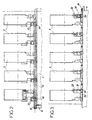
- FIG. 6 shows the entire punching bench in view On top.
- This bench has two rows of each five punching machines 2.
- a sheet metal, not shown, intended to be machined by these punching machines 2 is brought by a conveyor (see figures 7 to 12) in a direction represented in the drawing by an arrow referenced by the letter X.
- each punching machine 2 of the bench can move in a plane horizontal in a first direction Y represented by an arrow at drawing and perpendicular to the X direction, as well as in the X direction.
- Punching machines are not specially the object of the invention will not be described in detail here. It can for example be punching machines such as those described in the patent application FR-2 750 627. The description which follows relates essentially to the means allowing the displacement of each of these punching machines according to a the X direction and the Y direction, and also on the means allowing the movement of the machined sheet.
- Figures 1 and 2 show the means allowing a displacement in direction X, i.e. in the direction of conveying of the machined sheet.
- the punching machines 2 are aligned in two rows. To each of these rows corresponds a frame 4 on which are mounted all the punching machines of the row.
- Each punching machine 2 is placed on a carriage 6 which can be move in direction X.
- This carriage 6 is mounted on rails of guide 8 and has guide shoes 10.
- the guide pads 10 may comprise in known manner balls or needles that come into contact with the guide rail corresponding.
- the guide rails 8 extend in the direction of movement of the carriage 6 and are fixed to the frame.
- a rack 12 Between the guide rails 8 and parallel to them is mounted a rack 12.
- the latter is movable longitudinally, that is, it can translate in direction X. It is guided to this effect by guide pads.
- An electric motor 16 comprising an output shaft at the free end of which is mounted a toothed wheel 18 allows the drive in translation of the rack 12.
- the motor 16 is mounted via a flange on the frame 4 and it extends vertically while the rack 12 extends in a horizontal plane.
- each carriage 6 On each carriage 6 are coaxially mounted a pinion 20 meshing with the rack 12 and a clutch 22. In position coupled to the clutch 22, when the rack 12 moves, the pinion 20 remains fixed and the rack 12 causes the carriage to move 6, while in the disengaged position, the pinion 20 is rotated, but the carriage 6 is not driven in translation and remains fixed.
- the rack 12 can thus be used for movement in the direction X of all the punching machines 2 of the corresponding row and it is also possible, thanks to the clutches 22 to move a punching machine independently of other punching machines.
- a "small" rack 24 is fixed, for example using screws and a pin, on the frame 4.
- An encoder pinion 26 associated with an encoder 28 is mounted on each carriage 6 and meshes with the fixed rack 24 corresponding.
- a brake 30 is provided coaxially between the encoder pinion 26 and the encoder 28.
- This encoder 28 is connected to an electronic device (not shown in the drawing) intended to control the punching bench and thus allows to know precisely, at any time, the position of the carriage 6.
- Means for moving the punching machine in the Y direction are visible in particular in FIGS. 4 and 5.
- the punching machine 2 is mounted on a carriage 32, itself mounted movable in translation in direction Y on the carriage 6.
- the carriage 32 is provided with guide pads 34 cooperating with guide rails 36 mounted on the carriage 6 parallel to the direction Y.
- the carriage 32 is moved using a belt 38 notched.
- This belt is mounted on two pulleys, a first pulley 40 drives the belt 38 while the second pulley 42 is conducted.
- the driving pulley 40 is mounted by means of a clutch 44 on a splined shaft 46.
- Belt 38 is a linear belt, both of which ends are fixed to a profile 48 integral with the carriage 32 and passing of course on the driving pulleys 40 and driven 42.
- the splined shaft 46 is rotated by an electric motor 50.
- the splined shaft 46 drives the driving pulley 40 and causes the carriage 32 to move, while in the disengaged position, the pulley 40 is not driven and the carriage 32 does not move.
- an encoder (not shown) is mounted on the axis of the driven pulley.
- a single splined shaft 46 is provided for all punching machines 2 in the same row.
- the fact that the tree is grooved, allows the driving pulley 40 and the clutch to slide relative to the shaft 46 when the corresponding carriage 6 moves relative to the direction X. Thanks to clutches 44, it is possible to move a carriage 32, and therefore the corresponding punching machine 2, independently other carts 32.
- the motor 50 drives the splined shaft 46 in the two directions of rotation, so as to allow the movement of carriages 32 in direction Y.
- Clutches 22 and 44 are electronically controlled control unit managing the punching bench.
- FIG 7 shows a side view of the machine set of Figures 1 to 6 as well as a device for feeding sheets and conveying these during machining.
- This device comprises a pair of rollers 52 placed each time between a set of two facing machines as well as at the upstream and downstream ends of the set of machine tools.
- Each roller 52 extends in the width direction of the sheet to be conveyed in the Y direction, i.e. the direction perpendicular to the direction movement of the sheet in the plane thereof.
- the rollers 52 have a length greater than the width of the sheet to be machined.
- the rolls are identical pair by pair and in each pair, they are interconnected by gears not shown so that driving a roller in a direction of rotation involves rotation of the other roller at the same speed in the opposite direction.
- Figure 8 shows the means to train the rollers 52. Two options are shown. In a strong line, we have represented a shaft 54 at the ends of which is each mounted a motor 56. the height of each pair of rollers 52 is mounted a clutch 58 associated with a bevel gear 60. A secondary shaft 62 connects each gear angle 60 to a corresponding roller 52.
- each pair of rollers is associated with a motor 64.
- the main shaft 54 is then unnecessary and only the secondary trees 62 are kept.
- These motors 64 are each connected to the control electronics. It is here also possible to convey several sheets simultaneously.
- rollers 66 placed upstream of all machine tools. These rollers 66 are driven by a motor not shown. The sheet is guided over the entire length of the set of machine tools as well as downstream of this set. She comes then on a conveyor 68 which pulls the sheet out of the set of machine tools once machining has been completed.
- the device for feeding and sheet metal conveying no longer has rollers but two clamps 70 sliding mounted on a rail 72 extending in the direction of the displacement of the sheet.
- a clamp 70 is placed rather upstream of the set of machine tools according to the invention in order to introduce a sheet in this set and one the second clamp is rather downstream of this together to extract a sheet introduced into this set.
- the two clamps 70 can also be moved in height, this is to say perpendicular to the plane of the machined sheet, to allow the passage of a sheet over the clamp.
- moving in both directions could be done using a rack system, or using a strap. It is also possible to use other means to move tools in both directions: for example cylinders pneumatic or hydraulic, or linear motors.
- each punching machine is mounted movable compared to other punching machines. It is possible to climb two or more tools on the same cart. So these two or more tools will always move the same way in one or two directions. Two tools can be joined with regard to the moving in one direction, but being independently movable in this which concerns the second position.
Abstract
Description
La présente invention concerne un ensemble de machines-outils, telles par exemple des poinçonneuses, destinées à usiner sensiblement simultanément une même tôle.The present invention relates to a set of machine tools, such as punching machines, intended for machining substantially the same sheet.
Il est connu, pour réaliser des gains de temps, de placer plusieurs machines-outils identiques, ou différentes, les unes à côté des autres et/ou les unes en face des autres. Ainsi, lorsqu'une tôle est apportée à cet ensemble de machines, la tôle a très peu de déplacement à effectuer pour être usinée par chacune de ces machines l'une après l'autre. Deux machines se trouvant en vis à vis usinent souvent simultanément la tôle, mais sauf dans le cas de configurations bien particulières, toutes les machines ne travaillent pas simultanément.It is known, to save time, to place several identical or different machine tools, one beside the others and / or facing each other. So when a sheet is brought to this set of machines, the sheet has very little movement to be carried out to be machined by each of these machines one after the other. Two machines facing each other often machine simultaneously the sheet, but except in the case of configurations well particular, not all machines work simultaneously.
On retrouve de tels ensembles de machines notamment dans le travail de tôles, par exemple pour poinçonner des tôles.We find such sets of machines especially in sheet metal work, for example to punch sheets.
Pour augmenter la rapidité d'exécution de cet ensemble de machines, il est connu de rendre les diverses machines composant cet ensemble mobile selon une direction (voir par exemple FR-A-2 750 627). Il s'agit, dans les machines de l'art antérieur connu, d'une direction perpendiculaire à la direction de convoyage des tôles à usiner. Ainsi, quand des machines mobiles se trouvent sur deux rangées se faisant face, elles se déplacent de telle sorte qu'elles s'approchent ou s'éloignent des machines leur faisant face.To increase the speed of execution of this set of machines, it is known to make the various machines making up this assembly movable in one direction (see for example FR-A-2 750 627). It is, in the machines of art known anterior, from a direction perpendicular to the direction of conveying of the sheets to be machined. So when mobile machines get are in two rows facing each other, they move in such a way so that they approach or move away from the machines facing them.
Ainsi, le processus d'usinage peut être très sensiblement accéléré.So the machining process can be very noticeably accelerated.
Le document DE-41 13 629 décrit un ensemble de machines alignées destinées à percer et fraiser automatiquement, de tous côtés, une pièce à usiner allongée. A cet effet, les diverses machines sont déplaçables et positionnables par un système de vis sans fin motorisé le long d'une broche montée sur un bâti.Document DE-41 13 629 describes a set of machines aligned for automatic drilling and milling on all sides, an elongated workpiece. For this purpose, the various machines are movable and positionable by a motorized worm system the along a spindle mounted on a frame.
L'invention a alors pour but de fournir un ensemble de machines-outils qui permet d'augmenter encore le gain de temps par rapport aux ensembles de machines-outils connus.The object of the invention is therefore to provide a set of machine tools which further increases the time saving by compared to known machine tool assemblies.
À cet effet, l'ensemble de machines-outils qu'elle propose comporte de façon connue au moins deux machines-outils pour l'usinage de la tôle, l'une au moins de ces machines-outils étant munie de moyens la rendant déplaçable selon une première direction, ainsi que des moyens permettant l'amenée et le convoyage d'une tôle.To this end, the set of machine tools it offers comprises in known manner at least two machine tools for machining sheet metal, at least one of these machine tools being provided with means making it movable in a first direction, as well as means allowing the supply and conveying of a sheet.
Selon l'invention, l'une au moins des machines-outils déplaçable selon une première direction est disposée sur un chariot ou similaire, et des moyens sont prévus pour déplacer chaque chariot selon une seconde direction. According to the invention, at least one of the machine tools movable in a first direction is placed on a carriage or similar, and means are provided for moving each carriage according to a second direction.
De cette manière, au moins une machine-outil est déplaçable selon les deux directions de déplacement prévues sur la machine. Il est alors possible de positionner cette machine outil au nombre d'au moins une par rapport à la tôle à usiner. Ce positionnement peut s'effectuer pendant le temps d'acheminement d'une nouvelle tôle à usiner vers l'ensemble de machines-outils. Cette opération s'effectue ainsi en temps masqué, alors que dans un ensemble de machines-outils de l'art antérieur, il est la plupart du temps nécessaire de déplacer la tôle à usiner durant son usinage pour que la tôle soit bien positionnée lors de son usinage par les diverses machines constituant l'ensemble.In this way, at least one machine tool can be moved according to the two directions of movement provided on the machine. It is then possible to position this machine tool at least at number one with respect to the sheet to be machined. This positioning can be done during the routing time of a new sheet to be machined to the set of machine tools. This is done in time masked, whereas in a set of machine tools of the prior art, it is most of the time necessary to move the sheet to be machined during its machining so that the sheet is well positioned during its machining by the various machines constituting the whole.
Étant donné que dans la pratique les plans d'usinage sont presque toujours réalisés en utilisant un repère orthogonal, les première et seconde directions sont avantageusement perpendiculaires.Since in practice the working planes are almost always made using an orthogonal coordinate system, the first and second directions are advantageously perpendicular.
Dans une première forme de réalisation, les moyens permettant le déplacement d'une machine-outil selon une direction comportent une crémaillère parallèle à cette direction et déplaçable longitudinalement à l'aide d'un moteur ainsi qu'un pignon muni d'un dispositif d'embrayage, le pignon étant destiné à venir engrener avec la crémaillère.In a first embodiment, the means allowing moving a machine tool in one direction has a rack parallel to this direction and movable longitudinally at using a motor and a pinion fitted with a clutch device, the pinion being intended to come to mesh with the rack.
Ces moyens peuvent servir à déplacer la ou les machine(s)-outil(s) dans une direction ou bien dans les deux directions.These means can be used to move the machine (s) -tool (s) in one direction or in both directions.
Les moyens permettant le déplacement d'une machine-outil selon une direction peuvent aussi comporter par exemple un arbre perpendiculaire à cette direction, entraíné en rotation par un moteur ainsi qu'une poulie montée de façon débrayable sur l'arbre, la poulie étant associée à une seconde poulie par l'intermédiaire d'une courroie sur laquelle est monté un chariot portant la machine-outil correspondante.The means for moving a machine tool in a direction can also include for example a tree perpendicular to this direction, driven in rotation by a motor as well than a pulley disengageably mounted on the shaft, the pulley being associated with a second pulley via a belt on which is mounted a carriage carrying the corresponding machine tool.
Bien entendu, d'autres moyens sont envisageables pour déplacer les machines-outils. Un moteur linéaire pourrait par exemple être utilisé.Of course, other means can be envisaged for move machine tools. A linear motor could for example be used.
Selon une forme de réalisation, l'ensemble selon l'invention comporte deux rangées parallèles de machines-outils se faisant face. Cette disposition est souvent réalisée, car elle convient très bien pour usiner des tôles qui sont symétriques ou bien quasi symétriques.According to one embodiment, the assembly according to the invention has two parallel rows of machine tools facing each other. This layout is often carried out, because it is very suitable for machining sheets which are symmetrical or almost symmetrical.
Dans cette configuration, chaque rangée de machines-outils est avantageusement montée sur un bâti. Une crémaillère mobile longitudinalement est alors avantageusement montée sur le bâti sur sensiblement toute la longueur de celui-ci et au niveau de chaque machine-outil montée sur le bâti, se trouve un pignon engrènant avec la crémaillère, un dispositif d'embrayage étant associé au pignon. Les moyens entraínant la crémaillère permettent ainsi l'entraínement de toutes les machines-outils de la rangée concernée. Lorsque la crémaillère se déplace dans un sens, les embrayages des pignons des machines-outils devant se déplacer dans le même sens sont en position embrayée, tandis que les autres sont en position débrayée. Il suffit de déplacer la crémaillère dans les deux sens selon une course prédéterminée pour positionner toutes les machines-outils de la rangée correspondante.In this configuration, each row of machine tools is advantageously mounted on a frame. A mobile rack longitudinally is then advantageously mounted on the frame on substantially the entire length thereof and at the level of each machine tool mounted on the frame, there is a pinion meshing with the rack, a clutch device being associated with the pinion. The means the rack thus allow the drive of all machine tools of the row concerned. When the rack moves in one direction, the clutches of the pinions of the machine tools having to move in the same direction are in the engaged position, while the others are in disengaged position. Just move the rack back and forth according to a predetermined stroke to position all the machine tools from the corresponding row.
Dans le cas d'un ensemble de machines-outils dont une partie des machines sont montées sur un bâti, il peut être envisagé qu'un arbre cannelé s'étende sur sensiblement toute la longueur du bâti et qu'une poulie entraínée de façon débrayable par l'arbre cannelé est associée à chaque machine-outil. De même qu'expliqué au paragraphe précédent, l'arbre cannelé peut entraíner toutes les machines-outils en déplacement dans la direction concernée.In the case of a set of machine tools, part of which machines are mounted on a frame, it can be considered that a tree grooved extends over substantially the entire length of the frame and that a pulley disengageably driven by the splined shaft is associated with each machine tool. As explained in the previous paragraph, the splined shaft can drive all machine tools on the move in the direction concerned.
Pour connaítre précisément la position des diverses machines-outils, l'ensemble selon l'invention comporte avantageusement au moins un codeur par machine-outil déplaçable, afin de connaítre la position exacte de celle-ci.To know precisely the position of the various machine tools, the assembly according to the invention advantageously comprises at least one encoder per movable machine tool, in order to know the position exact of it.
Les moyens permettant l'amenée et le convoyage d'une tôle comportent par exemple des paires de rouleaux disposées perpendiculairement au sens de convoyage de la tôle entre des machines-outils de l'ensemble, des moyens moteurs étant prévus pour entraíner ces rouleaux.The means allowing the supply and the conveying of a sheet for example have pairs of rollers arranged perpendicular to the direction of conveyance of the sheet between machine tools all, motor means being provided to drive these rolls.
Dans une variante de réalisation, les moyens permettant l'amenée et le convoyage d'une tôle comportent une paire de rouleaux disposées perpendiculairement au sens de convoyage de la tôle en aval de l'ensemble de machines-outils, des moyens moteurs étant prévus pour entraíner ces rouleaux.In an alternative embodiment, the means allowing the supply and conveyance of a sheet includes a pair of rollers arranged perpendicular to the sheet metal conveying direction downstream of all machine tools, motor means being provided for train these rollers.
Selon une autre forme de réalisation, les moyens permettant l'amenée et le convoyage d'une tôle comportent deux pinces montées coulissantes sur un rail.According to another embodiment, the means allowing the supply and the conveying of a sheet includes two clamps mounted sliding on a rail.
De toute façon, l'invention sera bien comprise à l'aide de la
description qui suit, en référence au dessin schématique annexé,
représentant à titre d'exemple non limitatif une forme de réalisation d'un
ensemble de machines-outils selon l'invention.
La présente invention est décrite ci-après en référence à un
banc de poinçonnage comportant plusieurs poinçonneuses 2. Les
poinçonneuses représentées au dessin ont une forme appelée "en col de
cygne". Bien entendu, d'autres types de poinçonneuses et d'autres outils
pourrait être utilisés sans pour autant sortir du cadre de l'invention.The present invention is described below with reference to a
punching bench with
La figure 6 montre l'ensemble du banc de poinçonnage en vue
de dessus. Ce banc comporte deux rangées de chacune cinq
poinçonneuses 2. Une tôle, non représentée, destinée à être usinée par
ces poinçonneuses 2 est apportée par un convoyeur (cf figures 7 à 12)
selon une direction représentée au dessin par une flèche référencée par la
lettre X. D'après le mode de réalisation de l'invention représenté au
dessin, chaque poinçonneuse 2 du banc peut se déplacer dans un plan
horizontal selon une première direction Y représentée par une flèche au
dessin et perpendiculaire à la direction X, ainsi que dans la direction X.Figure 6 shows the entire punching bench in view
On top. This bench has two rows of each five
Les poinçonneuses n'étant pas spécialement l'objet de l'invention ne seront pas décrites en détails ici. Il peut par exemple s'agir de poinçonneuses telles que celles décrites dans la demande de brevet FR-2 750 627. La description qui suit porte essentiellement sur les moyens permettant le déplacement de chacune de ces poinçonneuses selon d'une part la direction X et d'autre part la direction Y, et aussi sur les moyens permettant le déplacement de la tôle usiné.Punching machines are not specially the object of the invention will not be described in detail here. It can for example be punching machines such as those described in the patent application FR-2 750 627. The description which follows relates essentially to the means allowing the displacement of each of these punching machines according to a the X direction and the Y direction, and also on the means allowing the movement of the machined sheet.
Les figures 1 et 2 montrent les moyens permettant un déplacement selon la direction X, c'est à dire dans la direction du convoyage de la tôle usinée.Figures 1 and 2 show the means allowing a displacement in direction X, i.e. in the direction of conveying of the machined sheet.
Comme indiqué déjà ci-dessus, les poinçonneuses 2 sont
alignées sur deux rangées. A chacune de ces rangées correspond un bâti 4
sur lequel sont montées toutes fes poinçonneuses de la rangée.As already indicated above, the
Chaque poinçonneuse 2 est placée sur un chariot 6 pouvant se
déplacer dans la direction X. Ce chariot 6 est monté sur des rails de
guidage 8 et comporte des patins de guidage 10. Pour éviter les
frottements, les patins de guidage 10 peuvent comporter de façon connue
des billes ou des aiguilles qui viennent au contact du rail de guidage
correspondant. Les rails de guidage 8 s'étendent dans la direction de
déplacement du chariot 6 et sont fixés sur le bâti.Each punching
Entre les rails de guidage, 8 et parallèlement à ceux-ci, est
montée une crémaillère 12. Cette dernière est mobile longitudinalement,
c'est à dire qu'elle peut se translater dans la direction X. Elle est guidée à
cet effet par des patins de guidage. Un moteur électrique 16 comportant
un arbre de sortie à l'extrémité libre duquel est montée une roue dentée 18
permet l'entraínement en translation de la crémaillère 12. Le moteur 16 est
monté par l'intermédiaire d'une bride sur le bâti 4 et il s'étend
verticalement alors que la crémaillère 12 s'étend dans un plan horizontal.Between the
Sur chaque chariot 6 sont montés coaxialement un pignon 20
engrènant avec la crémaillère 12 et un embrayage 22. En position
accouplée de l'embrayage 22, lorsque la crémaillère 12 se déplace, le
pignon 20 reste fixe et la crémaillère 12 entraíne le déplacement du chariot
6, tandis qu'en position débrayée, le pignon 20 est entraíné en rotation,
mais le chariot 6 n'est pas entraíné en translation et reste fixe.On each
La crémaillère 12 peut ainsi servir aux déplacements dans la
direction X de toutes les poinçonneuses 2 de la rangée correspondante et
il est aussi possible, grâce aux embrayages 22 de déplacer une
poinçonneuse indépendamment des autres poinçonneuses.The
Afin de connaítre précisément la position du chariot 6 par
rapport à l'axe des X, un système de détection de position est prévu et est
représenté sur la figure 3.In order to know precisely the position of the
Parallèlement à la crémaillère 12, pour chaque chariot 6, une
"petite" crémaillère 24 est fixée, par exemple à l'aide de vis et d'une
goupille, sur le bâti 4. Un pignon codeur 26 associé à un codeur 28 est
monté sur chaque chariot 6 et engrène avec la crémaillère 24 fixe
correspondante. Avantageusement, un frein 30 est prévu coaxialement
entre le pignon codeur 26 et le codeur 28.Parallel to the
Ce codeur 28 est relié à un dispositif électronique (non
représenté au dessin) destiné à commander le banc de poinçonnage et
permet ainsi de connaítre avec précision, à tout moment, la position du
chariot 6.This
Les moyens permettant le déplacement de la poinçonneuse dans la direction Y sont visibles notamment sur les figures 4 et 5.Means for moving the punching machine in the Y direction are visible in particular in FIGS. 4 and 5.
La poinçonneuse 2 est montée sur un chariot 32, lui même
monté mobile en translation selon la direction Y sur le chariot 6. Le chariot
32 est muni de patins de guidage 34 coopérant avec des rails de guidage
36 montés sur le chariot 6 parallèlement à la direction Y.The punching
Le déplacement du chariot 32 s'effectue à l'aide d'une courroie
38 crantée. Cette courroie est montée sur deux poulies, une première
poulie 40 entraíne la courroie 38 tandis que la seconde poulie 42 est
menée. La poulie menante 40 est montée par l'intermédiaire d'un
embrayage 44 sur un arbre cannelé 46.The
La courroie 38 est une courroie linéaire dont les deux
extrémités sont fixées à un profilé 48 solidaire du chariot 32 et passant
bien entendu sur les poulies menante 40 et menée 42. L'arbre cannelé 46
est entraíné en rotation par un moteur 50 électrique.
En position embrayée de l'embrayage, l'arbre cannelé 46
entraíne la poulie menante 40 et provoque le déplacement du chariot 32,
tandis qu'en position débrayée, la poulie 40 n'est pas entraínée et le
chariot 32 ne bouge pas.In the clutch engaged position, the
Afin de connaítre la position exacte du chariot 32 par rapport
au chariot 6, et ainsi connaítre précisément la position en direction Y de la
poinçonneuse 2 correspondante, un codeur (non représenté) est monté sur
l'axe de la poulie menée.In order to know the exact position of the
Un seul arbre cannelé 46 est prévu pour toutes les
poinçonneuses 2 d'une même rangée. Le fait que l'arbre soit cannelé,
permet à la poulie menante 40 et à l'embrayage de coulisser par rapport à
l'arbre 46 lorsque le chariot 6 correspondant se déplace par rapport à la
direction X. Grâce aux embrayages 44, il est possible de déplacer un
chariot 32, et donc la poinçonneuse 2 correspondante, indépendamment
des autres chariots 32.A single
Le gain de temps avec un banc de poinçonnage selon
l'invention par rapport aux bancs de poinçonnage de l'art antérieur est très
sensible. Ainsi, pendant qu'une tôle à poinçonner est apportée face aux
poinçonneuses 2, par exemple à l'aide d'un convoyeur, les poinçonneuses
sont positionnées de manière à pouvoir poinçonner la tôle dès que celle-ci
est en place. Le moteur 16 entraíne la crémaillère 12 dans un sens puis
dans l'autre selon une course correspondant au déplacement maximal d'un
chariot 6. Pendant ce déplacement de la crémaillère 12, chaque
embrayage 22 correspondant à un chariot 6 reste en position embrayée le
temps nécessaire à son déplacement pour arriver dans la position
souhaitée.Save time with a punching bench according to
the invention compared to the punching benches of the prior art is very
sensitive. Thus, while a punching sheet is brought in front of the
En même temps, le moteur 50 entraíne l'arbre cannelé 46 dans
les deux sens de rotation, de manière à permettre le déplacement des
chariots 32 selon la direction Y.At the same time, the
Les embrayages 22 et 44 sont commandés par l'électronique
de commande gérant le banc de poinçonnage.
Tous ces réglages sont réalisés en temps masqué. Dans la
plupart des cas de figure, la tôle ne sera pas bougée pendant son usinage.
Les poinçonneuses 2 travaillent toutes sensiblement simultanément, tandis
qu'avec un banc de poinçonnage de l'art antérieur, il fallait généralement
placer différemment la tôle au cours du processus de poinçonnage pour
pouvoir réaliser tous les trous prévus. Les poinçonneuses travaillent alors,
avec un banc de l'art antérieur, une après l'autre ou aussi parfois deux par
deux. All these adjustments are made in masked time. In the
In most cases, the sheet will not be moved during machining.
The
La figure 7 montre en vue de côté l'ensemble de machines des
figures 1 à 6 ainsi qu'un dispositif d'amenée de tôles et de convoyage de
celles-ci durant l'usinage. Ce dispositif comporte une paire de rouleaux 52
placés chaque fois entre un ensemble de deux machines se faisant face
ainsi qu'aux extrémités amont et aval de l'ensemble de machines-outils.
Chaque rouleau 52 s'étend dans le sens de la largeur de la tôle à convoyer
dans la direction Y, c'est à dire la direction perpendiculaire à la direction
de déplacement de la tôle dans le plan de celle-ci. Sur le dessin, les
rouleaux 52 ont une longueur supérieure à la largeur de la tôle à usiner.
Toutefois, il est envisageable d'avoir des rouleaux de largeur sensiblement
moindre. Les rouleaux sont identiques paire par paire et dans chaque paire,
ils sont reliés entre eux par des engrenages non représentés de telle sorte
que l'entraínement d'un rouleau dans un sens de rotation implique la
rotation de l'autre rouleau à la même vitesse dans le sens contraire.Figure 7 shows a side view of the machine set of
Figures 1 to 6 as well as a device for feeding sheets and conveying
these during machining. This device comprises a pair of
La figure 8 montre les moyens permettant d'entraíner les
rouleaux 52. Deux options sont représentées. En trait fort, on a représenté
un arbre 54 aux extrémités duquel est chaque fois monté un moteur 56. À
la hauteur de chaque paire de rouleaux 52 est monté un embrayage 58
associé à un renvoi d'angle 60. Un arbre secondaire 62 relie chaque renvoi
d'angle 60 à un rouleau 52 correspondant.Figure 8 shows the means to train the
De cette manière, il est possible d'entraíner un rouleau de
chaque paire de rouleaux indépendamment des autres paires de rouleaux.
Ceci permet de convoyer deux ou plusieurs tôles. Bien entendu, tous les
moteurs 56 et embrayages 58 sont relié et commandés par l'électronique
de commande de l'ensemble des machines-outils.In this way, it is possible to drive a roller
each pair of rollers independently of the other pairs of rollers.
This allows two or more sheets to be conveyed. Of course, all
En traits mixtes est représentée une variante de réalisation. Ici,
chaque paire de rouleaux est associée à un moteur 64. L'arbre principal 54
est alors inutile et seuls les arbres secondaires 62 sont conservés. Ces
moteurs 64 sont chacun reliés à l'électronique de commande. Il est ici
également possible de convoyer plusieurs tôles simultanément.In dashed lines is shown an alternative embodiment. Here,
each pair of rollers is associated with a
Lorsque seules des tôles de grande longueur sont usinées, seule la présence d'une paire de rouleaux d'entraínement est nécessaire comme montré sur les figures 9 et 10.When only long sheets are machined, only the presence of a pair of drive rollers is necessary as shown in Figures 9 and 10.
On a alors une paire de rouleaux 66 placée en amont de
l'ensemble des machines outils. Ces rouleaux 66 sont entraínés par un
moteur non représenté. La tôle est guidée sur toute la longueur de
l'ensemble de machines-outils ainsi qu'en aval de cet ensemble. Elle vient
ensuite sur un convoyeur 68 qui assure la traction de la tôle hors de
l'ensemble de machines-outils une fois l'usinage réalisé.We then have a pair of
Sur les figures 11 et 12, le dispositif d'amenée et de
convoyage de la tôle ne comporte plus de rouleaux mais deux pinces 70
montées coulissantes sur un rail 72 s'étendant dans la direction du
déplacement de la tôle. Une pince 70 est placé plutôt en amont de
l'ensemble de machines-outils selon l'invention afin d'introduire une tôle
dans cet ensemble et une la seconde pince se trouve plutôt en aval de cet
ensemble pour extraire une tôle introduite dans cet ensemble.In FIGS. 11 and 12, the device for feeding and
sheet metal conveying no longer has rollers but two
Les deux pinces 70 peuvent aussi se déplacer en hauteur, c'est à dire perpendiculairement au plan de la tôle usinée, pour permettre le passage d'une tôle au dessus de la pince.The two clamps 70 can also be moved in height, this is to say perpendicular to the plane of the machined sheet, to allow the passage of a sheet over the clamp.
Comme il va de soi, l'invention ne se limite pas au mode de réalisation décrit ci-dessus à titre d'exemple non limitatif ; elle en embrasse au contraire toutes les variantes dans le cadre des revendications ci-après.It goes without saying that the invention is not limited to the mode of embodiment described above by way of nonlimiting example; she embraces it on the contrary, all the variants within the scope of the claims below.
Ainsi par exemple, les déplacements dans les deux directions pourraient être effectués à l'aide d'un système à crémaillère, ou bien à l'aide d'une courroie. Il est aussi envisageable d'utiliser d'autres moyens pour déplacer dans les deux directions les outils : par exemple des vérins pneumatiques ou hydrauliques, ou des moteurs linéaires.So for example, moving in both directions could be done using a rack system, or using a strap. It is also possible to use other means to move tools in both directions: for example cylinders pneumatic or hydraulic, or linear motors.
Dans l'exemple de réalisation, chaque poinçonneuse est montée mobile par rapport aux autres poinçonneuses. Il est possible de monter deux ou plusieurs outils sur un même chariot. Ainsi, ces deux ou plusieurs outils se déplaceront toujours de la même manière dans une ou deux directions. Deux outils peuvent être solidaires en ce qui concerne le déplacement selon une direction, mais être mobiles indépendamment en ce qui concerne la seconde position.In the exemplary embodiment, each punching machine is mounted movable compared to other punching machines. It is possible to climb two or more tools on the same cart. So these two or more tools will always move the same way in one or two directions. Two tools can be joined with regard to the moving in one direction, but being independently movable in this which concerns the second position.
Il est aussi envisageable, pour diminuer les coûts de revient du banc d'usinage selon l'invention, de laisser fixe un ou plusieurs outils et de positionner la tôle à usiner en fonction de ces outils fixes. Il est bien sûr également possible d'avoir quelques outils déplaçables selon un direction mais pas selon une seconde.It is also possible, to reduce the cost of the machining bench according to the invention, to leave one or more tools fixed and to position the sheet to be machined according to these fixed tools. It is of course also possible to have some tools that can be moved in one direction but not for a second.
Claims (12)
- Series of machine tools comprising at least two machine tools (2) for machining of metal plate, at least one of these machine tools being provided with means which enable it to be displaced in a first direction (Y), which is generally perpendicular to the direction of conveying of the metal plates to be machined, as well as means (52; 66; 70) which permit feeding and conveying of a metal plate;
characterised in that at least one of the machine tools (2), which can be displaced in the first direction (Y) is disposed on a carriage (6) or the like, and in that means are provided for displacing each carriage (6) in a second direction (X), which is generally parallel to the direction of conveying of the metal plates to be machined. - Series according to claim 1, characterised in that the first (Y) and second (X) directions are perpendicular.
- Series according to claim 1 or claim 2, characterised in that the means which permit displacement of a machine tool (2) in one direction comprise a rack (12), which is parallel to this direction, and can be displaced longitudinally by means of a motor (16), as well as a pinion (20) which is provided with a clutch device (22), the pinion (20) being designed to be engaged with the rack (12).
- Series according to any one of claims 1 to 3, characterised in that the means which permit displacement of a machine tool (2) in one direction comprise a shaft (46) which is perpendicular to this direction, and is rotated by a motor (50), as well as a pulley (40), which is fitted to the shaft in such a manner that it can be disengaged, the pulley (40) being associated with a second pulley (42) by means of a belt (38) on which there is fitted a carriage (32) which supports the corresponding machine tool (2).
- Series according to any one of claims 1 to 4, characterised in that it comprises two parallel rows of machine tools which are opposite one another.
- Series according to claim 5, characterised in that each row of machine tools is fitted on a frame (4).
- Series according to claim 6, characterised in that a rack (12), which is mobile longitudinally, is fitted on the frame (4) on substantially all of the length of the latter, and in that at the level of each machine tool (2) which is fitted on the frame, there is a pinion (20) which engages with the rack (12), a clutch device (22) being associated with the pinion (20).
- Series according to claim 6, characterised in that a grooved shaft (46) extends on substantially all the length of the frame (4), and in that a pulley (40), which is driven by the grooved shaft in such a manner that it can be disengaged, is associated with each machine tool (2).
- Series according to any one of claims 1 to 8, characterised in that it comprises at least one displaceable encoder (28) per machine tool (2), in order to determine the exact position of the latter.
- Series according to any one of claims 1 to 9, characterised in that the means which permit feeding and conveying of a metal plate comprise pairs of rollers (52), which are disposed perpendicularly to the direction of conveying of the metal plate, between machine tools in the series, drive means (56, 64) being provided in order to drive these rollers.
- Series according to any one of claims 1 to 9, characterised in that the means which permit feeding and conveying of a metal plate comprise a pair of rollers (66), which are disposed perpendicularly to the direction of conveying of the metal plate, downstream from the series of machine tools, drive means being provided in order to drive these rollers.
- Series according to any one of claims 1 to 9, characterised in that the means which permit feeding and conveying of a metal plate comprise two grippers (70), which are fitted such as to slide on a rail (72).
Applications Claiming Priority (3)
| Application Number | Priority Date | Filing Date | Title |
|---|---|---|---|
| FR9708817A FR2765510B1 (en) | 1997-07-07 | 1997-07-07 | ASSEMBLY OF MACHINE TOOLS FOR SUBSTANTIALLY SIMULTANEOUSLY WORKING A WORKPIECE |
| FR9708817 | 1997-07-07 | ||
| PCT/FR1998/001461 WO1999002301A1 (en) | 1997-07-07 | 1998-07-07 | Machine-tool assembly for substantially simultaneous machining of a sheet metal |
Publications (2)
| Publication Number | Publication Date |
|---|---|
| EP1011918A1 EP1011918A1 (en) | 2000-06-28 |
| EP1011918B1 true EP1011918B1 (en) | 2002-02-13 |
Family
ID=9509118
Family Applications (1)
| Application Number | Title | Priority Date | Filing Date |
|---|---|---|---|
| EP98936468A Expired - Lifetime EP1011918B1 (en) | 1997-07-07 | 1998-07-07 | Machine-tool assembly for substantially simultaneous machining of a sheet metal |
Country Status (5)
| Country | Link |
|---|---|
| EP (1) | EP1011918B1 (en) |
| AT (1) | ATE213194T1 (en) |
| DE (1) | DE69803858D1 (en) |
| FR (1) | FR2765510B1 (en) |
| WO (1) | WO1999002301A1 (en) |
Families Citing this family (1)
| Publication number | Priority date | Publication date | Assignee | Title |
|---|---|---|---|---|
| EP4338863A1 (en) * | 2022-09-13 | 2024-03-20 | Rychiger AG | Support for a processing tool for a strip material and device for processing a strip material |
Family Cites Families (4)
| Publication number | Priority date | Publication date | Assignee | Title |
|---|---|---|---|---|
| JPH0437422A (en) * | 1990-06-04 | 1992-02-07 | Amada Co Ltd | Device for composite working |
| DE4113629C2 (en) * | 1991-04-26 | 1995-02-23 | Goetz Metall Anlagen | Row drilling and milling machine |
| US5336025A (en) * | 1991-12-16 | 1994-08-09 | Honda Giken Kogyo Kabushiki Kaisha | Multi-spindle machine tool |
| DE4328801C2 (en) * | 1993-08-27 | 1996-05-30 | Praewema Werkzeugmaschinenfabr | Machining machine |
-
1997
- 1997-07-07 FR FR9708817A patent/FR2765510B1/en not_active Expired - Fee Related
-
1998
- 1998-07-07 DE DE69803858T patent/DE69803858D1/en not_active Expired - Lifetime
- 1998-07-07 AT AT98936468T patent/ATE213194T1/en active
- 1998-07-07 WO PCT/FR1998/001461 patent/WO1999002301A1/en active IP Right Grant
- 1998-07-07 EP EP98936468A patent/EP1011918B1/en not_active Expired - Lifetime
Also Published As
| Publication number | Publication date |
|---|---|
| DE69803858D1 (en) | 2002-03-21 |
| FR2765510A1 (en) | 1999-01-08 |
| WO1999002301A1 (en) | 1999-01-21 |
| EP1011918A1 (en) | 2000-06-28 |
| FR2765510B1 (en) | 1999-09-03 |
| ATE213194T1 (en) | 2002-02-15 |
Similar Documents
| Publication | Publication Date | Title |
|---|---|---|
| EP0115353B1 (en) | Device for displacing a profile to be machined in its longitudinal direction past work stations | |
| EP0248700B1 (en) | Packaging machine for "american" boxes | |
| EP2964434B1 (en) | Arrangement for cutting and ejecting waste, unit and machine provided with the same | |
| EP1011918B1 (en) | Machine-tool assembly for substantially simultaneous machining of a sheet metal | |
| FR2566377A1 (en) | MACHINE FOR PROCESSING AND INSERTING ELECTRONIC COMPONENTS AND METHOD FOR SUPPLYING AND TRANSFERRING ELECTRONIC COMPONENTS | |
| FR2526700A1 (en) | Workpiece pallet transport mechanism between stations - comprises guided truck with transverse guides for pallet and auger | |
| FR2504434A1 (en) | DEVICE FOR THE LONGITUDINAL TRANSFER OF PARTS FROM A FIRST POST TO A SECOND POST | |
| FR2593729A1 (en) | PLATE PROCESSING MACHINE, ESPECIALLY PUNCHING MACHINE | |
| EP1223003A1 (en) | Installation for the circulation of work-supporting pallets and pallet for said installation | |
| FR2695854A1 (en) | Device for milling cavities in plastic cards and embedding integrated circuits in said cavities. | |
| FR2517648A1 (en) | HOUSING CHAIN TRANSPORTER | |
| FR2905622A1 (en) | Mechanical manipulator for part assembling and/or controlling machine, has cylinders one of which has shaft connected with plate, and free end, where cylinders have input shafts simultaneously driven in rotation by single driving belt | |
| WO2003002435A2 (en) | Device for transporting parts for supplying machines | |
| FR2781416A1 (en) | Guide for printed copies in rotary printer folder consists of conveyor material, discharge gap between cylinders, guide body swiveling on axle and container | |
| EP0453984A2 (en) | Device for jogging sheets | |
| FR2488177A1 (en) | Machine feeding trays to and from machine tool - uses linearly reciprocating slides coupled selectively with trays traversing parallel rails | |
| EP0896856B1 (en) | Machine tool especially for superfinishing of cylindrical surfaces of revolution by means of a tangential running grinding belt | |
| FR2726258A1 (en) | DEVICE FOR TRANSFERRING PARTS FROM A FIRST CONVEYOR TO A SECOND CONVEYOR INCLUDING AN ENDLESS BELT CURVED CONVEYOR INSTALLATION | |
| FR2627410A1 (en) | ||
| FR2806945A1 (en) | PUNCHING CENTER, PARTICULARLY FOR PUNCHING SHEETS | |
| BE1004259A5 (en) | Machine drawing type drive automatic leaf. | |
| FR2668976A1 (en) | Device for bringing sheets of paper onto a lay-out board of printing machines and for aligning them thereon | |
| FR2476450A1 (en) | DEVICE FOR WORKING SHEET-LIKE OBJECTS, PARTICULARLY FOR CUTTING CIGAR CAPS IN TOBACCO LEAVES | |
| FR2696674A1 (en) | Method for making and machining parallel tabs on the two front surfaces of elongated pieces of wood and a two-end profiling machine for carrying out this method. | |
| FR2750626A1 (en) | DEVICE ALLOWING TO ADAPT THE SIZE OF A MACHINE-TOOL CLAMP |
Legal Events
| Date | Code | Title | Description |
|---|---|---|---|
| PUAI | Public reference made under article 153(3) epc to a published international application that has entered the european phase |
Free format text: ORIGINAL CODE: 0009012 |
|
| 17P | Request for examination filed |
Effective date: 20000207 |
|
| AK | Designated contracting states |
Kind code of ref document: A1 Designated state(s): AT BE CH DE ES FR GB IT LI NL SE |
|
| GRAG | Despatch of communication of intention to grant |
Free format text: ORIGINAL CODE: EPIDOS AGRA |
|
| 17Q | First examination report despatched |
Effective date: 20010430 |
|
| GRAG | Despatch of communication of intention to grant |
Free format text: ORIGINAL CODE: EPIDOS AGRA |
|
| GRAH | Despatch of communication of intention to grant a patent |
Free format text: ORIGINAL CODE: EPIDOS IGRA |
|
| GRAH | Despatch of communication of intention to grant a patent |
Free format text: ORIGINAL CODE: EPIDOS IGRA |
|
| GRAA | (expected) grant |
Free format text: ORIGINAL CODE: 0009210 |
|
| REG | Reference to a national code |
Ref country code: GB Ref legal event code: IF02 |
|
| AK | Designated contracting states |
Kind code of ref document: B1 Designated state(s): AT BE CH DE ES FR GB IT LI NL SE |
|
| PG25 | Lapsed in a contracting state [announced via postgrant information from national office to epo] |
Ref country code: NL Free format text: LAPSE BECAUSE OF FAILURE TO SUBMIT A TRANSLATION OF THE DESCRIPTION OR TO PAY THE FEE WITHIN THE PRESCRIBED TIME-LIMIT Effective date: 20020213 Ref country code: IT Free format text: LAPSE BECAUSE OF FAILURE TO SUBMIT A TRANSLATION OF THE DESCRIPTION OR TO PAY THE FEE WITHIN THE PRESCRIBED TIME-LIMIT;WARNING: LAPSES OF ITALIAN PATENTS WITH EFFECTIVE DATE BEFORE 2007 MAY HAVE OCCURRED AT ANY TIME BEFORE 2007. THE CORRECT EFFECTIVE DATE MAY BE DIFFERENT FROM THE ONE RECORDED. Effective date: 20020213 Ref country code: GB Free format text: LAPSE BECAUSE OF FAILURE TO SUBMIT A TRANSLATION OF THE DESCRIPTION OR TO PAY THE FEE WITHIN THE PRESCRIBED TIME-LIMIT Effective date: 20020213 Ref country code: AT Free format text: LAPSE BECAUSE OF FAILURE TO SUBMIT A TRANSLATION OF THE DESCRIPTION OR TO PAY THE FEE WITHIN THE PRESCRIBED TIME-LIMIT Effective date: 20020213 |
|
| REF | Corresponds to: |
Ref document number: 213194 Country of ref document: AT Date of ref document: 20020215 Kind code of ref document: T |
|
| REG | Reference to a national code |
Ref country code: CH Ref legal event code: EP |
|
| REF | Corresponds to: |
Ref document number: 69803858 Country of ref document: DE Date of ref document: 20020321 |
|
| PG25 | Lapsed in a contracting state [announced via postgrant information from national office to epo] |
Ref country code: SE Free format text: LAPSE BECAUSE OF FAILURE TO SUBMIT A TRANSLATION OF THE DESCRIPTION OR TO PAY THE FEE WITHIN THE PRESCRIBED TIME-LIMIT Effective date: 20020513 |
|
| PG25 | Lapsed in a contracting state [announced via postgrant information from national office to epo] |
Ref country code: DE Free format text: LAPSE BECAUSE OF FAILURE TO SUBMIT A TRANSLATION OF THE DESCRIPTION OR TO PAY THE FEE WITHIN THE PRESCRIBED TIME-LIMIT Effective date: 20020514 |
|
| NLV1 | Nl: lapsed or annulled due to failure to fulfill the requirements of art. 29p and 29m of the patents act | ||
| PG25 | Lapsed in a contracting state [announced via postgrant information from national office to epo] |
Ref country code: LI Free format text: LAPSE BECAUSE OF NON-PAYMENT OF DUE FEES Effective date: 20020731 Ref country code: CH Free format text: LAPSE BECAUSE OF NON-PAYMENT OF DUE FEES Effective date: 20020731 Ref country code: BE Free format text: LAPSE BECAUSE OF NON-PAYMENT OF DUE FEES Effective date: 20020731 |
|
| GBV | Gb: ep patent (uk) treated as always having been void in accordance with gb section 77(7)/1977 [no translation filed] |
Effective date: 20020213 |
|
| PG25 | Lapsed in a contracting state [announced via postgrant information from national office to epo] |
Ref country code: ES Free format text: LAPSE BECAUSE OF FAILURE TO SUBMIT A TRANSLATION OF THE DESCRIPTION OR TO PAY THE FEE WITHIN THE PRESCRIBED TIME-LIMIT Effective date: 20020829 |
|
| PLBE | No opposition filed within time limit |
Free format text: ORIGINAL CODE: 0009261 |
|
| STAA | Information on the status of an ep patent application or granted ep patent |
Free format text: STATUS: NO OPPOSITION FILED WITHIN TIME LIMIT |
|
| BERE | Be: lapsed |
Owner name: *JEANDEAUD JEAN-CLAUDE Effective date: 20020731 |
|
| 26N | No opposition filed |
Effective date: 20021114 |
|
| REG | Reference to a national code |
Ref country code: CH Ref legal event code: PL |
|
| PG25 | Lapsed in a contracting state [announced via postgrant information from national office to epo] |
Ref country code: FR Free format text: LAPSE BECAUSE OF NON-PAYMENT OF DUE FEES Effective date: 20030331 |
|
| REG | Reference to a national code |
Ref country code: FR Ref legal event code: ST |