EP0099279B1 - Chaîne de transfert libre de pièces entre des postes de travail successifs avec moyen de stockage dynamique - Google Patents
Chaîne de transfert libre de pièces entre des postes de travail successifs avec moyen de stockage dynamique Download PDFInfo
- Publication number
- EP0099279B1 EP0099279B1 EP19830401180 EP83401180A EP0099279B1 EP 0099279 B1 EP0099279 B1 EP 0099279B1 EP 19830401180 EP19830401180 EP 19830401180 EP 83401180 A EP83401180 A EP 83401180A EP 0099279 B1 EP0099279 B1 EP 0099279B1
- Authority
- EP
- European Patent Office
- Prior art keywords
- chain
- transfer chain
- transfer
- storage
- station
- Prior art date
- Legal status (The legal status is an assumption and is not a legal conclusion. Google has not performed a legal analysis and makes no representation as to the accuracy of the status listed.)
- Expired
Links
Images
Classifications
-
- B—PERFORMING OPERATIONS; TRANSPORTING
- B65—CONVEYING; PACKING; STORING; HANDLING THIN OR FILAMENTARY MATERIAL
- B65G—TRANSPORT OR STORAGE DEVICES, e.g. CONVEYORS FOR LOADING OR TIPPING, SHOP CONVEYOR SYSTEMS OR PNEUMATIC TUBE CONVEYORS
- B65G47/00—Article or material-handling devices associated with conveyors; Methods employing such devices
- B65G47/34—Devices for discharging articles or materials from conveyor
- B65G47/46—Devices for discharging articles or materials from conveyor and distributing, e.g. automatically, to desired points
- B65G47/50—Devices for discharging articles or materials from conveyor and distributing, e.g. automatically, to desired points according to destination signals stored in separate systems
-
- B—PERFORMING OPERATIONS; TRANSPORTING
- B65—CONVEYING; PACKING; STORING; HANDLING THIN OR FILAMENTARY MATERIAL
- B65G—TRANSPORT OR STORAGE DEVICES, e.g. CONVEYORS FOR LOADING OR TIPPING, SHOP CONVEYOR SYSTEMS OR PNEUMATIC TUBE CONVEYORS
- B65G37/00—Combinations of mechanical conveyors of the same kind, or of different kinds, of interest apart from their application in particular machines or use in particular manufacturing processes
- B65G37/02—Flow-sheets for conveyor combinations in warehouses, magazines or workshops
Definitions
- the invention relates to a chain whose role is to transfer workpieces between successive workstations where specific operations are carried out, either manually or automatically.
- chain is used here to designate any conveyor or any conveyor which is of any type suitable for the parts to be moved and the work stations.
- such a chain has distinct bearing surfaces on which the workpieces to be transferred are placed.
- the workpiece carriers which have an upper face specially intended for receiving the parts to be moved will be called pallets.
- the transfer chain is closed in a loop on itself thanks to a return section which returns from the second to the first end, from the unloading station to the loading station.
- a transfer chain thus established is subject to two types of disturbance, either a short-term incident affecting one of the stations, or a long-term breakdown of the one of the posts.
- the main purpose of the invention is to provide a solution which, without requiring a large surface area or volume, makes it possible to obtain, at least in relation to the workstations most exposed to incidents and breakdowns, a quantity of parts accumulated high enough to ensure extended operation of the chain in the event of an incident or breakdown at a work station.
- None of these documents relates to a transfer chain circulating in a loop between workstations and to which is added a common dynamic storage loop, with the possibility of feeding the workstations as well from the chain of transfer only from the common dynamic storage loop.
- a transfer chain which is preferably but not necessarily in a closed loop, comprising a loading station, spaced-apart work stations, an unloading station, workpiece pallets moved between these stations, to which is added a chain of dynamic storage common to all workstations, arranged in a closed loop
- secondary access chains are installed between the common dynamic storage chain and at least some of the intervals separating the workstations from the transfer chain . Referrals are provided for passing, when necessary, pallets from the transfer chain to the common dynamic storage chain and vice versa, by means of secondary access chains.
- each secondary access chain is itself a closed loop which communicates by two points spaced apart by a on the one hand with the transfer chain, on the other hand with the common dynamic storage chain.
- the invention does not prohibit the existence of individual interpost stocks.
- a selective means of stopping the circulating pallets upstream of the switching of this chain with each secondary access chain there is also provided on the transfer chain a space for the storage of a few pallets between at least some of the work stations and the switching of this transfer chain with the secondary chain access which precedes the work station considered .
- the transfer chain, the common dynamic storage chain and the secondary access chains are arranged in the same plane; the transfer chain is closed in a loop and contains the common storage chain itself closed in a loop so that the latter chain is parallel as a whole to the return section of the transfer chain.
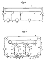
- Figure 1 shows a transfer chain 1 which is made in a closed loop on itself to move workpiece pallets, in a closed circuit, through a loading station 2 where parts are placed, or wedged, or attached on the pallets, then by successive work stations spaced A, B, C, where the parts undergo one or more operations, to arrive at an unloading station 3 where the parts are removed from the pallets.
- the loading station 2 is considered to be the upstream end or first end of the transfer chain 1 and the unloading station 3 is the downstream end or second end.
- the transfer chain continues with a return section 4 between the unloading station 3 and the loading station 2. In this return section 4 the pallets are generally devoid of parts.
- a common dynamic storage chain 6 is added to the transfer chain 1 and secondary chains 7 for access between the dynamic storage chain 6 and the transfer chain 1.
- secondary access chain 7 it is often preferable but not always necessary to provide a secondary access chain 7 at each interval 5 between work stations. It is also possible, but it can be dispensed with in many cases, to also provide an outlet chain 8 after the unloading station 3 between the transfer chain 1 and the dynamic storage chain 6, and a chain of input 9, before the loading station 2 between the dynamic storage chain 6 and the transfer chain 1.
- each switch 10, 11 is mounted a switch element suitable for the conveyor used and capable of either letting a pallet pass over the transfer chain 1 or over the storage chain 6 in deviating from its path, or deflect a pallet from the transfer chain 1 to the secondary chain 7 or vice versa from the latter to this one, or deviate a pallet from the storage chain 6 to the secondary chain 7 or vice versa from the latter to this one the.
- a switch element suitable for the conveyor used and capable of either letting a pallet pass over the transfer chain 1 or over the storage chain 6 in deviating from its path, or deflect a pallet from the transfer chain 1 to the secondary chain 7 or vice versa from the latter to this one, or deviate a pallet from the storage chain 6 to the secondary chain 7 or vice versa from the latter to this one the.
- the switch element suitable for the conveyor used and capable of either letting a pallet pass over the transfer chain 1 or over the storage chain 6 in deviating from its path, or deflect a pallet from the transfer chain 1 to the secondary chain 7 or vice vers
- a transfer chain 1 combined with a common storage chain 6 as just described, provides the following advantages.
- the pallets move in direction F, between stations 2, A, B, C ... 3 at their own rate.
- the transfer chain moves continuously in direction F ,; during a production without incidents the pallets move between the different stations at the same speed as this but can be immobilized for a certain time next to each station, (so that the corresponding operation is carried out), without for as much the chain is immobilized.
- suitable means effect either a lifting or a lateral displacement of the pallet with respect to the chain, or a holding or immobilization of the pallet so that the latter can slide on the moving chain.
- station L If an incident occurs, even a fairly long one of the stations called here station L, the other stations continue to operate since pallets intended for the next station L + 1 are taken one by one from the storage chain 6 according to their availability and the parts leaving the previous station L - 1 are introduced one by one on the storage chain 6.
- a prolonged incident or breakdown at station L is necessary so that all the stations stop when the storage chain 6 is empty of parts intended at the downstream stations replaced by those coming from the L - 1 station. Even in this situation, the stations can operate up to the L - 1 station, the parts leaving it being then introduced onto the storage chain 6.
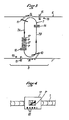
- each secondary access chain 7 produced according to the example in FIG. 2 there is a branch 7A going from the storage chain 6 to the transfer chain 1 and a branch 7B going in the opposite direction.
- a stop barrier 12 is mounted on the branch 7A, near the transfer chain 1.
- the secondary stop chains 7 are in motion.
- the part of the branch 7A between the switch 11 and the barrier 12 is furnished with parts intended for the immediately next work station.
- the switch 10 of each secondary access chain 7 with the transfer chain 1 there is a section 5A of each interval 5 on which one can accumulate upstream of a barrier 13 parts intended for the work that follows.
- the chains 1, 6, 7 include means necessary for correct operation with a view to the transfer of pallets loaded with parts from one of these chains to the other.
- FIG. 3 shows that in addition to the stop barriers 12 and 14 mounted on the branches 7A and 7B of the access chains 7, a barrier 15 is provided on the transfer chain 1, upstream in the direction F, of the switch 10 and a barrier 16 on the storage chain 6 upstream in the direction F 2 of the switch 11. These barriers 15, 16 are controlled in connection with the switches 10, 11 depending on whether one wishes to leave pass the pallets on a chain 6 or 1, or transfer pallets using the secondary access chain 7.
- Each pallet 17 (FIG. 4) is provided with an identification means, for example magnetic, which makes it possible to recognize it.
- this means of identification represents the state of the part P carried by this pallet, for example the designation of the work station where this part will have to undergo its next operation or that of the unloading station.
- the identification means are modified each time a pallet 17 leaves a work station where the part P has undergone an operation.
- Reading means 19 are placed along the chains 1, 6 in suitable places, preferably near the barriers 15, 16 (FIG. 3) so that the switching of a pallet takes place. carried by chain 6 to chain 1, or vice versa.
- a pallet can cross a workstation without stopping, by being moved by the transfer chain 1; it can also be taken out of a workstation by the secondary access chain 7 which follows this station and be sent to the common dynamic storage chain 6 to be sent further from this chain 6 to another station on the transfer chain 1.
- the common dynamic storage chain gives great flexibility to the operation of the assembly and a longer duration of autonomy in the event of an incident or breakdown than small individual stocks interposed alone.
- the invention does not exclude, as has been shown, the use and the advantages of the latter which are likely to be combined with the storage chain, a common dynamic.
- the access chain 7 can be replaced by a pallet carrier which moves alternately between the chains 1 and 6; in this case, means of monitoring obvious to those skilled in the art are associated with means of detecting incidents or breakdowns in order to carry out the transfer of the pallets with priority and in the appropriate direction (see FIG. 1).
Landscapes
- Engineering & Computer Science (AREA)
- Mechanical Engineering (AREA)
- Warehouses Or Storage Devices (AREA)
- Multi-Process Working Machines And Systems (AREA)
- Branching, Merging, And Special Transfer Between Conveyors (AREA)
- Control Of Conveyors (AREA)
Applications Claiming Priority (2)
| Application Number | Priority Date | Filing Date | Title |
|---|---|---|---|
| FR8210052 | 1982-06-09 | ||
| FR8210052A FR2528400A1 (fr) | 1982-06-09 | 1982-06-09 | Chaine de transfert libre de pieces entre des postes de travail successifs avec moyen de stockage dynamique |
Publications (2)
| Publication Number | Publication Date |
|---|---|
| EP0099279A1 EP0099279A1 (fr) | 1984-01-25 |
| EP0099279B1 true EP0099279B1 (fr) | 1986-02-26 |
Family
ID=9274814
Family Applications (1)
| Application Number | Title | Priority Date | Filing Date |
|---|---|---|---|
| EP19830401180 Expired EP0099279B1 (fr) | 1982-06-09 | 1983-06-09 | Chaîne de transfert libre de pièces entre des postes de travail successifs avec moyen de stockage dynamique |
Country Status (5)
| Country | Link |
|---|---|
| EP (1) | EP0099279B1 (enExample) |
| JP (1) | JPS59500761A (enExample) |
| DE (1) | DE3362279D1 (enExample) |
| FR (1) | FR2528400A1 (enExample) |
| WO (1) | WO1983004404A1 (enExample) |
Families Citing this family (6)
| Publication number | Priority date | Publication date | Assignee | Title |
|---|---|---|---|---|
| DE3343809C2 (de) * | 1983-12-03 | 1994-12-08 | Wurster & Dietz Maschf | Verfahren und Vorrichtung zum Transportieren und Bearbeiten von Werkstücken, insbesondere von Hölzern |
| CH664138A5 (de) * | 1984-10-12 | 1988-02-15 | Grapha Holding Ag | Fliessfertigungsstrecke fuer druckerzeugnisse. |
| JPH05181527A (ja) * | 1991-12-27 | 1993-07-23 | Mitsubishi Electric Corp | 自動搬送装置 |
| DE4400925C2 (de) * | 1994-01-14 | 1996-10-02 | Haensel Otto Gmbh | Speicher für Warenstücke |
| DE9406061U1 (de) * | 1994-04-12 | 1995-08-10 | Mts Modulare Transport Systeme Gmbh, Vomp | Sortieranlage zum Sortieren von einzeln geförderten Gegenständen |
| CH721462A1 (de) * | 2023-12-22 | 2025-06-30 | Ferag Ag | Anlage und Verfahren zum Sortieren und Zwischenspeichern von Stückgütern |
Family Cites Families (1)
| Publication number | Priority date | Publication date | Assignee | Title |
|---|---|---|---|---|
| DE1431426A1 (de) * | 1964-01-16 | 1969-02-06 | Jean Immarigeon | Verbesserungen an Waehlfoerdervorrichtungen |
-
1982
- 1982-06-09 FR FR8210052A patent/FR2528400A1/fr active Granted
-
1983
- 1983-06-09 DE DE8383401180T patent/DE3362279D1/de not_active Expired
- 1983-06-09 WO PCT/FR1983/000114 patent/WO1983004404A1/fr not_active Ceased
- 1983-06-09 JP JP58501858A patent/JPS59500761A/ja active Granted
- 1983-06-09 EP EP19830401180 patent/EP0099279B1/fr not_active Expired
Also Published As
| Publication number | Publication date |
|---|---|
| WO1983004404A1 (fr) | 1983-12-22 |
| EP0099279A1 (fr) | 1984-01-25 |
| DE3362279D1 (en) | 1986-04-03 |
| JPS59500761A (ja) | 1984-05-04 |
| JPH0336731B2 (enExample) | 1991-06-03 |
| FR2528400B1 (enExample) | 1984-12-28 |
| FR2528400A1 (fr) | 1983-12-16 |
Similar Documents
| Publication | Publication Date | Title |
|---|---|---|
| EP3245147B1 (fr) | Système et procédé de séquencement pour au moins un poste de préparation | |
| US4273234A (en) | Conveyor storage system | |
| EP3393939B1 (fr) | Système de stockage tampon et de séquencement de charges en amont d'au moins un poste de préparation | |
| EP2158144B1 (fr) | Systeme automatise de preparation de colis | |
| EP2487123B1 (fr) | Ensemble comprenant un poste de préparation de commandes avec au moins une cheminée d'accumulation verticale et de distribution séquencée de contenants. | |
| EP0099279B1 (fr) | Chaîne de transfert libre de pièces entre des postes de travail successifs avec moyen de stockage dynamique | |
| WO2017207152A1 (fr) | Système de stockage tampon et de séquencement de charges comprenant deux élévateurs | |
| FR2969588A1 (fr) | Installation de stockage de produits et convoyeur equipant une telle installation | |
| FR3007310A1 (fr) | Unite de production de produits manufactures comprenant un magasin automotique apte a etre associe a l execution de taches d un processus de fabrication | |
| FR2508003A1 (fr) | Machine de manutention d'objets, en particulier machine d'etiquetage ou de remplissage, pour recipients tels que des bouteilles | |
| WO2018167436A1 (fr) | Dispositif de transfert d'objets | |
| FR2816223A1 (fr) | Procede et dispositif pour le tri d'objets au moyen de transporteurs lineaires a parcours croises | |
| EP0841265A1 (fr) | Installation de convoyage pour préparation d'ensemble d'objets | |
| FR2654710A1 (fr) | Dispositif d'acheminement plan, a geometrie adaptable, pour des supports de pieces a traiter dans une pluralite de postes. | |
| FR2751627A1 (fr) | Installation pour l'emmagasinage temporaire d'articles et procede de commande du fonctionnement de cette installation | |
| BE1003960A7 (fr) | Procede et ensemble transporteur pour l'assemblage d'elements sur une base. | |
| FR2707965A1 (fr) | Installation mixte de transfert de palettes. | |
| FR2922877A1 (fr) | Transstockeur avec nacelle a convoyeur embarque pour magasin de stockage automatise. | |
| FR2718107A1 (fr) | Ligne de conditionnement pour des rangées ou des lits de produits, et dispositif de recyclage pour cette ligne. | |
| JPH04235819A (ja) | 作物の選別用搬送装置 | |
| FR2894234A1 (fr) | Procede de transfert et de stockage,dans une installation pour l'accumulation et la restitution de produits et dispositif accumulateur concu pour la mise en oeuvre du procede. | |
| FR2607116A1 (fr) | Magasin mecanise comprenant une pluralite de cellules de stockage d'articles | |
| FR2679538A1 (fr) | Procede pour le deplacement d'objets par rapport a une aire et dispositif de mise en óoeuvre, notamment pour le tri d'objets et pour constituer des jeux. | |
| FR2537107A1 (fr) | Perfectionnements au stockage dynamique des charges | |
| EP0153201A2 (fr) | Procédé et appareil pour la dérivation à des postes de travail d'articles déplacés le long d'un convoyeur |
Legal Events
| Date | Code | Title | Description |
|---|---|---|---|
| PUAI | Public reference made under article 153(3) epc to a published international application that has entered the european phase |
Free format text: ORIGINAL CODE: 0009012 |
|
| 17P | Request for examination filed |
Effective date: 19830616 |
|
| AK | Designated contracting states |
Designated state(s): CH DE IT LI |
|
| RAP1 | Party data changed (applicant data changed or rights of an application transferred) |
Owner name: LA TELEMECANIQUE ELECTRIQUE |
|
| ITF | It: translation for a ep patent filed | ||
| GRAA | (expected) grant |
Free format text: ORIGINAL CODE: 0009210 |
|
| AK | Designated contracting states |
Designated state(s): CH DE IT LI |
|
| REF | Corresponds to: |
Ref document number: 3362279 Country of ref document: DE Date of ref document: 19860403 |
|
| PLBE | No opposition filed within time limit |
Free format text: ORIGINAL CODE: 0009261 |
|
| STAA | Information on the status of an ep patent application or granted ep patent |
Free format text: STATUS: NO OPPOSITION FILED WITHIN TIME LIMIT |
|
| 26N | No opposition filed | ||
| ITTA | It: last paid annual fee | ||
| PGFP | Annual fee paid to national office [announced via postgrant information from national office to epo] |
Ref country code: DE Payment date: 19980612 Year of fee payment: 16 |
|
| PGFP | Annual fee paid to national office [announced via postgrant information from national office to epo] |
Ref country code: CH Payment date: 19980701 Year of fee payment: 16 |
|
| PG25 | Lapsed in a contracting state [announced via postgrant information from national office to epo] |
Ref country code: LI Free format text: LAPSE BECAUSE OF NON-PAYMENT OF DUE FEES Effective date: 19990630 Ref country code: CH Free format text: LAPSE BECAUSE OF NON-PAYMENT OF DUE FEES Effective date: 19990630 |
|
| REG | Reference to a national code |
Ref country code: CH Ref legal event code: PL |
|
| PG25 | Lapsed in a contracting state [announced via postgrant information from national office to epo] |
Ref country code: DE Free format text: LAPSE BECAUSE OF NON-PAYMENT OF DUE FEES Effective date: 20000503 |