EP0099104A2 - Druckgiessverfahren - Google Patents
Druckgiessverfahren Download PDFInfo
- Publication number
- EP0099104A2 EP0099104A2 EP83106811A EP83106811A EP0099104A2 EP 0099104 A2 EP0099104 A2 EP 0099104A2 EP 83106811 A EP83106811 A EP 83106811A EP 83106811 A EP83106811 A EP 83106811A EP 0099104 A2 EP0099104 A2 EP 0099104A2
- Authority
- EP
- European Patent Office
- Prior art keywords
- pressure
- casting
- melt
- mold
- gas pressure
- Prior art date
- Legal status (The legal status is an assumption and is not a legal conclusion. Google has not performed a legal analysis and makes no representation as to the accuracy of the status listed.)
- Granted
Links
- 238000005266 casting Methods 0.000 title claims abstract description 96
- 239000000155 melt Substances 0.000 claims abstract description 45
- 230000000694 effects Effects 0.000 claims abstract description 4
- 238000000034 method Methods 0.000 claims description 18
- 230000008569 process Effects 0.000 claims description 12
- 238000004512 die casting Methods 0.000 claims description 6
- 238000007711 solidification Methods 0.000 claims description 3
- 230000008023 solidification Effects 0.000 claims description 3
- 239000000463 material Substances 0.000 abstract description 8
- 239000007789 gas Substances 0.000 description 25
- 238000002425 crystallisation Methods 0.000 description 5
- 230000008025 crystallization Effects 0.000 description 5
- 238000009423 ventilation Methods 0.000 description 4
- 229910052751 metal Inorganic materials 0.000 description 3
- 239000002184 metal Substances 0.000 description 3
- 230000036962 time dependent Effects 0.000 description 3
- IJGRMHOSHXDMSA-UHFFFAOYSA-N Atomic nitrogen Chemical compound N#N IJGRMHOSHXDMSA-UHFFFAOYSA-N 0.000 description 2
- 238000010586 diagram Methods 0.000 description 2
- 230000002787 reinforcement Effects 0.000 description 2
- 230000004044 response Effects 0.000 description 2
- 238000013022 venting Methods 0.000 description 2
- 229910000838 Al alloy Inorganic materials 0.000 description 1
- 229910000789 Aluminium-silicon alloy Inorganic materials 0.000 description 1
- HCHKCACWOHOZIP-UHFFFAOYSA-N Zinc Chemical compound [Zn] HCHKCACWOHOZIP-UHFFFAOYSA-N 0.000 description 1
- 230000009471 action Effects 0.000 description 1
- 229910045601 alloy Inorganic materials 0.000 description 1
- 239000000956 alloy Substances 0.000 description 1
- 230000008901 benefit Effects 0.000 description 1
- 230000008859 change Effects 0.000 description 1
- 239000002131 composite material Substances 0.000 description 1
- 238000001816 cooling Methods 0.000 description 1
- 238000005429 filling process Methods 0.000 description 1
- 238000010438 heat treatment Methods 0.000 description 1
- 229910001338 liquidmetal Inorganic materials 0.000 description 1
- 238000004519 manufacturing process Methods 0.000 description 1
- 238000002844 melting Methods 0.000 description 1
- 230000008018 melting Effects 0.000 description 1
- 229910052757 nitrogen Inorganic materials 0.000 description 1
- 238000002360 preparation method Methods 0.000 description 1
- 238000007789 sealing Methods 0.000 description 1
- 239000000725 suspension Substances 0.000 description 1
- XLYOFNOQVPJJNP-UHFFFAOYSA-N water Chemical compound O XLYOFNOQVPJJNP-UHFFFAOYSA-N 0.000 description 1
- 229910052725 zinc Inorganic materials 0.000 description 1
- 239000011701 zinc Substances 0.000 description 1
Images


Classifications
-
- B—PERFORMING OPERATIONS; TRANSPORTING
- B22—CASTING; POWDER METALLURGY
- B22D—CASTING OF METALS; CASTING OF OTHER SUBSTANCES BY THE SAME PROCESSES OR DEVICES
- B22D18/00—Pressure casting; Vacuum casting
Definitions
- the invention relates to a die casting process in which the melt is conveyed from a melt container to a casting mold and fills it under the effect of a pressure difference which is produced between the melting container and the casting mold, so that the melt is filled under vacuum, atmospheric during the filling of the casting mold and increased pressure.
- a die casting method is known in which the melt present in a liquid metal container flows to the casting mold via a closed material line and fills it under the influence of a pressure difference in the melt container and in the casting mold.
- the mold is filled at atmospheric pressure.
- a suitable vacuum is created in the casting mold, so that one can thus control the speed of the complete filling of the mold.
- a disadvantage of this process is that the melt solidifies under the existing vacuum or low pressure conditions. This makes it impossible to get one Control of the crystallization process in the entire volume of the casting, especially in the case of a complicated shape. This has a negative influence on the physical-mechanical properties of the casting.
- the invention has for its object to design the die casting process of the type mentioned so that the mold filling and crystallization process can be safely controlled for all areas of the casting with minimal energy losses in order to be able to produce castings with excellent physical-mechanical properties from different materials.
- This object is achieved on the basis of the method of the type mentioned at the outset, according to the invention, in that, after the casting mold has been filled to a certain height, an additional gas pressure is generated in one or some cavities which have not yet been filled and which is substantially greater than that currently in the casting mold existing gas pressure is, at the same time the additionally generated gas pressure is compensated for by a gas pressure generated on the other side of the casting mold.
- the additionally generated gas pressure can be maintained in the casting mold until the melt has completely solidified, or can be varied, in particular increased, from the time the pressure is generated until the crystallization process is completed.
- the process according to the invention has the advantage that the additional gas pressure begins to act on the melt at a point in time which is selected as a function of the shape and the material of the casting mold, where the pressure is generated within the mold.
- the casting mold filling and the crystallization of the melt are influenced, these two processes being able to be controlled simultaneously and with a minimal expenditure of energy. This enables the production of castings with excellent physical-mechanical properties, regardless of the shape of the castings.
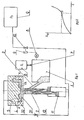
- the device shown in FIG. 1 for carrying out the die casting method has a melt container 1 which is connected to a casting mold 3 via a material line 2.
- the casting mold 3 consists of two parts, a lower half-mold 31 and an upper half-mold 32.
- a casting cavity 4 is formed between the two half-molds 31 and 32. Additional cavities 5 are present in the upper half mold 32.
- the melt container 1 is connected to a compressed gas source 6 via a valve 7.
- the pressure P 1 in the compressed gas source 6 corresponds to the casting pressure.
- the melt container 1 is provided with a pressure measuring device 8, which is connected via a converter 9 and a valve 10 to a gas container 13 with high pressure P 3 .
- an intensifier cylinder 11 with a stepped piston which is connected on the one hand via a control throttle 12 and a pipe to the additional cavities 5 and on the other hand via a further pipe and the valve 10 to the gas container 13.
- the casting process in this embodiment takes place as follows: after preparation of the melt, a pressure difference is generated between the melt container 1 and the casting mold 3, so that, regardless of whether there is a vacuum, atmospheric or increased pressure in the casting mold 3, the casting cavity 4 via the material line is filled. During the filling process, the casting pressure rises due to the overcoming of the frictional forces, the hydraulic height of the melt and the throttling action of the gases escaping through the ventilation openings, so that the filling takes place gradually and suddenly.
- the casting pressure P T p changes, for example as a result of a change in the cross section of the casting.
- the converter 9 takes effect. It opens the valve 10 so that gas from the gas container 13 is passed to the additional cavities 5 of the casting mold 3 which are not yet filled and to the booster cylinder 11, as a result of which the high pressure P 3 in the casting mold 3 . prevails.
- the flow of melt from the melt container 1 is interrupted by the movement of the stepped piston in the booster cylinder 11 and the complete filling of the casting mold 3 with the melt is ended. After pressure shut-off, cooling and removal of the finished casting, the casting cycle is repeated.
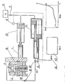
- the melt container consists of a cylinder 1 which is connected to the casting mold by a pouring tube.
- the casting mold is composed of a left half mold 31 and a right half mold 32 and has a casting cavity 4 and additional cavities 5, namely risers.
- the cylinder 1 is connected via a valve 7, a pipeline and a power cylinder 18 equipped with a pressure measuring device 8 to a pressure source 6 with a pressure P 1 .
- the power cylinder 18 is connected to an intensifier cylinder 11, which is connected on the one hand via a pipe to the casting cavity 4 and on the other hand via a valve 14 to a gas container 13 with high pressure P 3 .
- the pressure measuring device 8 is connected to the additional cavity 5 and the booster cylinder 11 via a converter 9 and a valve 10.
- a control throttle 12 is seated in the connecting line between the converter 9 and the additional cavity 5.
- pistons for motor vehicles are to be cast from an AlSi alloy which have a jacket wall thickness of 6 mm, a reinforcement ring in the lower area of the jacket, a reinforcement of 20 mm in the area of the piston pin eyes and a piston head thickness of 25 mm .
- the two-part mold 3 is made of metal and has a composite core for the central opening and cores for the radial openings. Venting channels, a pouring tube and additional cavities 5 forming risers are also formed in the casting mold 3.
- a gas pressure of 60 MPa is generated in the booster cylinder 11 by opening the valve 14.
- the valve 14 is later closed and a measured amount of melt is poured into the cylinder 1.
- a pressure is generated from the compressed gas source 6 in the power cylinder 18 and in the booster cylinder 11.
- the piston of the power cylinder 18 conveys the melt, which fills the casting cavity 4 of the casting mold 3.
- the casting pressure or delivery pressure P TP displayed by the pressure measuring device 8 changes. If the riser is partially filled, the casting pressure changes at point "a" in FIG. 4. After a signal from the pressure measuring device 8, the converter 9 is actuated so that the valve 10 opens.
- the stepped piston of the booster cylinder 11 is driven, as a result of which a pressure of 300 MPa prevails in the risers forming the additional cavities 5.
- the pressure thus produced is removed until the casting has completely crystallized.
- the device of FIG. 5 has a container 1 filled with molten metal, which is connected to the casting mold 3 via a material line 2.
- the casting cavity 4 is located between the upper half mold 31 and the lower half mold 32 of the casting mold 3.
- the additional cavities 5, namely risers, are provided in the upper half mold 32.
- the melt container 1 is connected to the pressure source 6 with a pressure P 1 via a valve 7.
- the melt container 1 and the space of the casting mold 3 are equipped with a pressure measuring device 8, which is provided with a converter 9. Via the valve 10, the converter 9 is connected to the gas container 13 at high pressure P 3 .
- the gas container 13 is connected via the valve 10 to the booster cylinder 11, which is connected to the lower half mold 31.
- the connection between the piston antechamber of the booster cylinder 11 and the additional cavities 5 of the casting mold is made via the control throttle 12.
- the space of the casting mold 3 is connected to a vacuum container 17 via a pipeline and a valve 16.
- components of a motor vehicle suspension are cast from aluminum alloy, in a complicated thin and thick-walled version with thicknesses of 4 to 25 mm.
- the thicker areas are concentrated in three places and are 300 to 400 mm away from the central opening, whereby a complicated ribbing with a rib height of up to 90 mm is provided.
- the casting process takes place in a two-part metal mold, which is in a hermetically sealed chamber is arranged.
- the separating surface of the two half molds 31 and 32 is complicated.
- the risers are formed over the massive areas of the casting. Vent channels are incorporated in the mold itself.
- the cavities between the individual ribs are designed as inlays, with ventilation channels being provided between them.
- a high pressure is generated in the additional cavity 5 of the casting mold 3 and is compensated for by the step piston of the booster cylinder 11.
- the high pressure is maintained until the solidification process has ended, while the vacuum only prevails until the mold 3 is filled. After the high pressure has been released, the casting is removed.
- the device of FIG. 7 has a melt container 1, which is connected via the material line 2 to the casting mold 3, which is composed of a left half mold 31 and a right half mold 32 and surrounds the casting cavity 4 formed therebetween.
- the additional cavities 5, namely the risers, are incorporated in the left half mold 31.
- the melt container 1 is via the valve 7 to the compressed gas source 6 connected with the pressure P 1 .
- the compressed gas source 6 is connected to the mold 3 via a valve 15.
- a pressure measuring device 8 is attached to the melt container 1 and is provided with a converter 9 which is connected via the valve 10 to the gas container 13 with high pressure P 3 .
- the gas container 13 and the booster cylinder 11 are connected to each other and connected to the right half mold 32.
- the two-part mold is provided with elastic seals.
- a deep and wide channel is worked out between the sealing ring and the casting cavity, which is connected to the casting cavity by ventilation channels. Further ventilation channels and a space for a riser are provided in the casting mold.
- melt made of technically pure zinc is introduced, which is pressurized to 10 bar with nitrogen.
- a pressure of 10 bar is then set in the melt container 1 - casting mold 3 system. Due to the pressure difference generated, the mold 3 is filled up to the level AA, which corresponds to point 2a in FIG. 8, so that the casting pressure changes.
- the converter 9, which opens the valve 10, is actuated by a signal from the pressure measuring device 8. This builds up in the unfilled additional Cavity 5 of the mold 3 to a pressure of 96 bar, which is compensated for by the pressure from the booster cylinder 11.
- the flow of melt from the melt container 1 is interrupted by the movement of the stepped piston of the booster cylinder 11.
- the mold 3 is completely filled under high pressure. After the crystallization process has ended, the pressure in the casting mold 3 is reduced, the casting is cooled and removed.
Landscapes
- Engineering & Computer Science (AREA)
- Mechanical Engineering (AREA)
- Molds, Cores, And Manufacturing Methods Thereof (AREA)
- Electrical Discharge Machining, Electrochemical Machining, And Combined Machining (AREA)
- Blow-Moulding Or Thermoforming Of Plastics Or The Like (AREA)
- Casting Or Compression Moulding Of Plastics Or The Like (AREA)
- External Artificial Organs (AREA)
- Separation By Low-Temperature Treatments (AREA)
- Encapsulation Of And Coatings For Semiconductor Or Solid State Devices (AREA)
- Mechanical Treatment Of Semiconductor (AREA)
- Battery Electrode And Active Subsutance (AREA)
- Crystals, And After-Treatments Of Crystals (AREA)
- Apparatus For Radiation Diagnosis (AREA)
- Manufacture, Treatment Of Glass Fibers (AREA)
- Reinforced Plastic Materials (AREA)
- Inorganic Insulating Materials (AREA)
- Manufacture Of Alloys Or Alloy Compounds (AREA)
- Iron Core Of Rotating Electric Machines (AREA)
- Manufacture Of Motors, Generators (AREA)
- Input Circuits Of Receivers And Coupling Of Receivers And Audio Equipment (AREA)
- Superconductors And Manufacturing Methods Therefor (AREA)
- Ceramic Products (AREA)
- Powder Metallurgy (AREA)
- Casting Devices For Molds (AREA)
Abstract
Description
- Die Erfindung betrifft ein Druckgießverfahren, bei dem die Schmelze aus einem Schmelzebehälter zu einer Gießform gefördert wird und sie unter der Wirkung eines Druckunterschiedes füllt, der zwischen dem Schmelzbehälter und der Gießform hergestellt wird, so daß während des Füllens der Gießform die Schmelze unter Vakuum, atmosphärischem und erhöhtem Druck steht.
- Aus der JP-A-14385 ist ein Druckgießverfahren bekannt, bei dem die in einem Flüssigmetallbehälter vorhandene Schmelze über eine geschlossene Materialleitung zur Gießform fließt und sie unter der Einwirkung eines Druckunterschiedes im Schmelzebehälter und in der Gießform füllt. Die Füllung der Gießform beginnt bei atmosphärischem Druck. Wenn die Schmelze eine bestimmte Höhe erreicht hat, wird in der Gießform ein geeignetes Vakuum erzeugt, so daß man auf diese Weise die Geschwindigkeit der vollständigen Formausfüllung steuern kann. Nach dem Füllen der Gießform und nach dem Erstarren der Schmelze wird das Gußstück herausgenommen.
- Ein Nachteil dieses Verfahrens liegt darin, daß die Schmelze unter den vorhandenen Vakuum- oder Niederdruckbedingungen erstarrt. Dadurch ist es unmöglich, eine Steuerung des Kristallisationsvorganges im ganzen Volumen des Gußstückes, besonders bei einer kompliziert gestalteten Form, vorzunehmen. Dies hat einen negativen Einfluß auf die physikalisch-mechanischen Eigenschaften des Gußstückes.
- Der Erfindung liegt die Aufgabe zugrunde, das Druckgießverfahren der eingangs genannten Art so auszubilden, daß der Formfüll- und Kristallisationsvorgang für alle Bereiche des Gußstückes bei minimalen Energieverlusten sicher gesteuert werden kann, um Gußstücke mit hervorragenden physikalisch-mechanischen Eigenschaften aus verschiedenen Werkstoffen herstellen zu können.
- Diese Aufgabe wirdausgehend von dem Verfahren der eingangs genannten Art, erfindungsgemäß dadurch gelöst, daß nach dem Füllen der Gießform bis zu einer bestimmten Höhe, in einem oder einigen noch nicht gefüllten Hohlräumen ein zusätzlicher Gasdruck erzeugt wird, der wesentlich größer als der momentan in der Gießform vorhandene Gasdruck ist, wobei gleichzeitig der zusätzlich erzeugte Gasdruck durch einen auf der anderen Seite der Gießform erzeugten Gasdruck ausgeglichen wird.
- Der zusätzlich erzeugte Gasdruck kann bis zur vollständigen Erstarrung der Schmelze in der Gießform beibehalten werden oder vom Zeitpunkt der Druckerzeugung bis zur Vollendung des Kristallisationsvorganges variiert, insbesondere gesteigert werden.
- Das erfindungsgemäße Verfahren hat den Vorteil, daß der zusätzliche Gasdruck auf die Schmelze zu einem Zeitpunkt zu wirken beginnt, der in Abhängigkeit von der Formgebung und dem Material der Gießform gewählt wird, wobei der Druck innerhalb der Gießform erzeugt wird. Auf diese Weise wird auf die Gießformfüllung und die Kristallisation der Schmelze Einfluß genommen, wobei diese beiden Vorgänge gleichzeitig und mit einem minimalen Energieaufwand gesteuert werden können. Dies ermöglicht die Herstellung von Gußstücken mit ausgezeichneten physikalisch-mechanischen Eigenschaften, und zwar unabhängig von der Form der Gußstücke.
- Anhand von Zeichnungen werden Ausführungsbeispiele der Erfindung näher erläutert. Es zeigt:
- Fig. 1 schematisch eine erste Ausführungsform einer Vorrichtung zur Durchführung des Druckgießverfahrens mit Schmelzezuführung aufgrund unterschiedlicher Drucke in Gießform und Schmelzebehälter
- Fig. 2 in einem Diagramm den Verlauf des Gießdrucks über der Zeit
- Fig. 3 schematisch eine zweite Ausführungsform mit Atmosphärendruck in der Gießform und mit mit Hilfe eines Kolbens erzeugtem Gießdruck
- Fig. 4 den zeitabhängigen Verlauf des Gießdrucks bei der Ausführungsform von Fig. 3
- Fig. 5 schematisch eine dritte Ausführungsform mit Vakuum in der Gießform und einem aus unterschiedlichen Gasdrucken resultierendem Gießdruck
- . Fig. 6 den zeitabhängigen Verlauf des Gießdrucks bei der Ausführungsform von Fig. 5
- Fig. 7 schematsich eine vierte Ausführungsform mit Überdruck in der Gießform und einem aus unterschiedlichen Gasdrucken resultierenden Gießdruck und
- Fig. 8 den zeitabhängigen Verlauf des Gießdrucks bei der Ausführungsform von Fig. 7.
- Die in Fig. 1 gezeigte Vorrichtung zur Durchführung des Druckgießverfahrens hat einen Schmelzebehälter 1, der über eine Materialleitung 2 mit einer Gießform 3 verbunden ist. Die Gießform 3 besteht aus zwei Teilen, einer unteren Halbform 31 und einer oberen Halbform 32. Zwischen den beiden Halbformen 31 und 32 wird ein Gießhohlraum 4 ausgebildet. In der oberen Halbform 32 sind zusätzliche Hohlräume 5 vorhanden. Der Schmelzebehälter 1 ist an eine Druckgasquelle 6 über ein Ventil 7 angeschlossen. Der Druck P1 in der Druckgasquelle 6 entspricht dem Gießdruck. Der Schmelzebehälter 1 ist mit einem Druckmeßgerät 8 versehen, das über einen Umsetzer 9 und ein Ventil 10 mit einem Gasbehälter 13 mit hohem Druck P3 verbunden ist. Im unteren Bereich der Gießform 3 ist ein Verstärkerzylinder 11 mit einem Stufenkolben angeordnet, der einerseits über eine Regeldrossel 12 und eine Rohrleitung mit den zusätzlichen Hohlräumen 5 und andererseits über eine weitere Rohrleitung und das Ventil 10 mit dem Gasbehälter 13 verbunden ist.
- Der Gießvorgang bei dieser Ausführung erfolgt folgendermaßen: Nach Vorbereitung der Schmelze wird zwischen dem Schmelzebehälter 1 und der Gießform 3 ein Druckunterschied erzeugt, so daß unabhängig davon, ob in der Gießform 3 ein Vakuum, atmosphärischer oder erhöhter Druck herrscht, der Gießhohlraum 4 über die Materialleitung gefüllt wird. Während des Füllvorgangs steigt der Gießdruck aufgrund der Überwindung der Reibungskräfte, der hydraulischen Höhe der Schmelze und der Drosselwirkung der durch Entlüftungsöffnungen entweichenden Gase, so daß das Füllen allmählich und sprungartig erfolgt.
- Beim Erreichen einer bestimmten Höhe der Schmelze, die mit der Gerade A-A bzw. Punkt "a" in dem Diagramm von Fig. 2 dargestellt ist, verändert sich der Gießdruck P Tp , z.B. infolge einer Änderung des Gußstückquerschnitts. Auf ein Signal aus dem Druckmeßgerät 8 für den Gießdruck wird der Umsetzer 9 wirksam. Er öffnet das Ventil 10, so daß Gas aus dem Gasbehälter 13 zu den noch nicht gefüllten zusätzlichen Hohlräumen 5 der Gießform 3 und zu dem Verstärkerzylinder 11 geleitet wird, wodurch in der Gießform 3 der hohe Druck P3. herrscht. Durch die Bewegung des Stufenkolbens im Verstärkerzylinder 11 wird der Zufluß von Schmelze aus dem Schmelzebehälter 1 unterbrochen und das vollständige Füllen der Gießform 3 mit Schmelze beendet. Nach Druckabsperrung, Abkühlung und Entnahme des fertiggestellten Gußstückes wird der Gießzyklus wiederholt.
- Bei der Vorrichtung von Fig. 3 besteht der Schmelzebehälter aus einem Zylinder 1, der mit der Gießform durch ein Gießrohr verbunden ist. Die Gießform setzt sich aus einer linken Halbform 31 und einer rechten Halbform 32 zusammen und hat einen Gießhohlraum 4 und zusätzliche Hohlräume 5, nämlich Steiger. Der Zylinder 1 ist über ein Ventil 7, eine Rohrleitung und einen mit einem Druckmeßgerät 8 ausgestatteten Kraftzylinder 18 mit einer Druckquelle 6 mit einem Druck P1 angeschlossen. Der Kraftzylinder 18 ist mit einem Verstärkerzylinder 11 verbunden, der einerseits über eine Rohrleitung mit dem Gießhohlraum 4 und andererseits über ein Ventil 14 mit einem Gasbehälter 13 mit hohem Druck P3 verbunden ist. Das Druckmeßgerät 8 ist über einen Umsetzer 9 und ein Ventil 10 mit dem zusätzlichen Hohlraum 5 und dem Verstärkerzylinder 11 verbunden. In der Verbindungsleitung zwischen dem Umsetzer 9 und dem zusätzlichen Hohlraum 5 sitzt eine Regeldrossel 12.
- Mit der Ausführung von Fig. 3 sollen Kolben für Kraftfahrzeuge aus einer AlSi-Legierung gegossen werden, die eine Mantelwandstärke von 6 mm, einen Verstärkungsring im unteren Bereich des Mantels, eine Verstärkung von 20 mm im Bereich der Kolbenbolzenaugen und eine Kolbenbodenstärke von 25 mm haben. Die zweiteilige Gießform 3 besteht aus Metall und hat einen zusammengesetzten Kern für die zentrale öffnung und Kerne für die Radialöffnungen. In der Gießform 3 sind noch Entlüftungskanäle, ein Gießrohr und zusätzliche Hohlräume 5 bildende Steiger ausgebildet.
- In dem Verstärkerzylinder 11 wird, ausgehend vom Gasbehälter 13, durch öffnen des Ventils 14 ein Gasdruck von 60 MPa erzeugt. Später wird das Ventil 14 geschlossen und eine abgemessene Menge an Schmelze in den Zylinder 1 eingegossen. Durch öffnen des Ventils 7 wird aus der Druckgasquelle 6 im Kraftzylinder 18 und im Verstärkerzylinder 11 ein Druck erzeugt. Der Kolben des Kraftzylinders 18 fördert die Schmelze, die den Gießhohlraum 4 der Gießform 3 füllt. Wenn der zusätzliche Hohlraum 5 der Gießform 3 gefüllt ist, tritt eine Änderung des von dem Druckmeßgerät 8 angezeigten Gießdruckes bzw. Förderdruckes PTP (Ftg. 4) ein. Wenn der Steiger teilweise gefüllt ist, ändert sich der Gießdruck im Punkt "a" von Fig. 4. Nach einem Signal aus dem Druckmeßgerät 8 wird der Unsetzer 9 betätigt, so daß sich das Ventil 10 öffnet. Dadurch wird der Stufenkolben des Verstärkerzylinders 11 angetrieben, wodurch in den die zusätzlichen Hohlräume 5 bildenden Steigern ein Druck von 300 MPa herrscht. Der so hergestellte Druck wird bis zur vollständigen Kristallisation des Gußstückes entnommen. Nach einer entsprechenden Wärmebehandlung hat das so erzeugte Gußstück folgende Eigenschaften: Zugfestigkeit δβ = 320 bis 360 N/cm2; Streckgrenze δS = 270 bis 200 N/cm2; Dehnung δ > 3%; Brinellhärte HB = 120 bis 140.
- Die Vorrichtung von Fig. 5 hat einen mit Metallschmelze gefüllten Behälter 1, der mit der Gießform 3 über eine Materialleitung 2 verbunden ist. Zwischen der oberen Halbform 31 und der unteren Halbform 32 der Gießform 3 befindet sich der Gießhohlraum 4. In der oberen Halbform 32 sind die zusätzlichen Hohlräume 5, nämlich Steiger, vorgesehen. Der Schmelzebehälter 1 ist über ein Ventil 7 mit der Druckquelle 6 mit einem Druck P1 verbunden. Der Schmelzebehälter 1 und der Raum der Gießform 3 sind mit einem Druckmeßgerät 8 ausgestattet, das mit einem Umsetzer 9 versehen ist. Über das Ventil 10 ist der Umsetzer 9 an den Gasbehälter 13 mti hohem Druck P3 angeschlossen. Der Gasbehälter 13 ist über das Ventil 10 mit dem Verstärkerzylinder 11 verbunden, der an der unteren Halbform 31 angeschlossen ist. Die Verbindung zwischen dem Kolbenvorraum des Verstärkerzylinders 11 und den zusätzlichen Hohlräumen 5 der Gießform erfolgt über die Regeldrossel 12. Der Raum der Gießform 3 ist über eine Rohrleitung und ein Ventil 16 mit einem Vakuumbehälter 17 verbunden.
- Mit der Ausführung von Fig. 5 werden Bauteile einer Kraftfahrzeugaufhängung aus Alulegierung, in komplizierter dünn- und dickwandiger Ausführung mit Stärken von 4 bis 25 mm gegossen. Die dickeren Bereiche sind an drei Stellen konzentriert und sind von der Mittenöffnung 300 bis 400 mm entfernt, wobei eine komplizierte Verrippung mit einer Rippenhöhe bis 90 mm vorgesehen ist. Der Gießvorgang erfolgt in einer zweiteiligen Metallform, die in einer hermetisch abgedichteten Kammer angeordnet ist.
- Die Trennfläche der beiden Halbformen 31 und 32 ist kompliziert. Die Steiger sind über den massenreichen Bereichen des Gußstückes ausgebildet. In der Gießform selbst sind Entlüftungskanäle eingearbeitet. Die Hohlräume zwischen den einzelnen Rippen sind als Einlegestücke ausgebildet, wobei dazwischen Entlüftungskanäle vorgesehen sind. Vor dem Beginn des Gießvorgangs wird in der Kammer mit der Gießform 3 durch öffnen des Ventils 16 über die Vakuumquelle 17 ein Vakuum von 0,1 - 0,2 MPa erzeugt. Infolge des hergestellten Druckunterschieds zwischen dem Schmelzebehälter 1 und der Gießform 3 beginnt die Füllung des Gießhohlraums 4. Wenn die Schmelze die Entlüftungskanäle an der Trennfläche auszufüllen beginnt, ändert sich der Gießdruck. Auf ein Signal vom Druckmeßgerät 8 wird der Umsetzer 9 betätigt, der das Ventil 10 öffnet. Dadurch wird im zusätzlichen Hohlraum 5 der Gießform 3 ein hoher Druck erzeugt, der von dem Stufenkolben des Verstärkerzylinders 11 ausgeglichen wird. Der Hochdruck wird bis zur Beendigung des Erstarrungsvorganges beibehalten, während das Vakuum nur bis zur Füllung der Gießform 3 herrscht. Nach Abbau des Hochdrucks wird das Gußstück herausgenommen.
- Die Vorrichtung von Fig. 7 hat einen Schmelzebehälter 1, der über die Materialleitung 2 mit der Gießform 3 verbunden ist, die sich aus einer linken Halbform 31 und einer rechten Halbform 32 zusammensetzt und den dazwischen ausgebildeten Gießhohlraum 4 umschließt. In der linken Halbform 31 sind die zusätzlichen Hohlräume 5, nämlich die Steiger, eingearbeitet. Der Schmelzebehälter 1 ist über das Ventil 7 an die Druckgasquelle 6 mit dem Druck P1 angeschlossen. Die Druckgasquelle 6 ist über ein Ventil 15 mit der Gießform 3 verbunden. An dem Schmelzebehälter 1 ist ein Druckmeßgerät 8 angebracht, das mit einem Umsetzer 9 versehen ist, der über das Ventil 10 an den Gasbehälter 13 mit hohem Druck P3 angeschlossen ist. Der Gasbehälter 13 und der Verstärkerzylinder 11 sind miteinander verbunden und an die rechte Halbform 32 angeschlossen. Der Kolbenvorraum des Verstärkerzylinders 11 ist mit den zusätzlichen Hohlräumen 5 verbunden. Mit der Ausführung von Fig. 7 werden Bauteile mit Verrippungen gegossen, die in Wasserdampf bei 150°C und einem Druck von 10 MPa eingesetzt werden, was eine Festigkeit δβ = 300 bis 320 N/cm2 und eine Dehnung δ >20% erfordert.
- Die zweiteilige Gießform ist mit elastischen Dichtungen versehen. Zwischen dem Dichtungsring und dem Gießhohlraum ist ein tiefer und breiter Kanal ausgearbeitet, der durch Entlüftungskanäle mit dem Gießhohlraum verbunden ist. In der Gießform sind weitere Entlüftungskanäle und ein Raum für einen Steiger vorgesehen.
- In dem Schmelzebehälter 1 wird Schmelze aus technisch reinem Zink eingebracht, die mit Stickstoff unter einen Druck von 10 bar gesetzt wird. Nachher wird im System Schmelzebehälter 1 - Gießform 3 ein Druck von 10 bar eingestellt. Durch den erzeugten Druckunterschied wird die Gießform 3 bis zum Niveau A-A, was dem Punkt 2a in Fig. 8 entspricht, gefüllt, so daß sich der Gießdruck ändert. Durch ein Signal des Druckmeßgeräts 8 wird der Umsetzer 9 betätigt, der das Ventil 10 öffnet. Dadurch baut sich in dem nicht gefüllten zusätzlichen Hohlraum 5 der Gießform 3 einen Druck von 96 bar auf, der durch den Druck aus dem Verstärkerzylinder 11 ausgeglichen wird. Durch die Bewegung des Stufenkolbens des Verstärkerzylinders 11 wird der Zufluß von Schmelze aus dem Schmelzebehälter 1 unterbrochen. Die vollständige Füllung der Gießform 3 erfolgt unter hohem Druck. Nach Beendigung des Kristallisationsvorgangs wird der Druck in der Gießform 3 abgebaut, das Gußstück wird gekühlt und herausgenommen.
Claims (4)
Priority Applications (1)
| Application Number | Priority Date | Filing Date | Title |
|---|---|---|---|
| AT83106811T ATE30126T1 (de) | 1982-07-14 | 1983-07-11 | Druckgiessverfahren. |
Applications Claiming Priority (2)
| Application Number | Priority Date | Filing Date | Title |
|---|---|---|---|
| BG8257405A BG34491A1 (en) | 1982-07-14 | 1982-07-14 | Method for casting under pressure |
| BG57405/82 | 1982-07-14 |
Publications (3)
| Publication Number | Publication Date |
|---|---|
| EP0099104A2 true EP0099104A2 (de) | 1984-01-25 |
| EP0099104A3 EP0099104A3 (en) | 1984-02-22 |
| EP0099104B1 EP0099104B1 (de) | 1987-10-07 |
Family
ID=3911019
Family Applications (1)
| Application Number | Title | Priority Date | Filing Date |
|---|---|---|---|
| EP83106811A Expired EP0099104B1 (de) | 1982-07-14 | 1983-07-11 | Druckgiessverfahren |
Country Status (17)
| Country | Link |
|---|---|
| EP (1) | EP0099104B1 (de) |
| JP (1) | JPS5947062A (de) |
| AT (1) | ATE30126T1 (de) |
| AU (1) | AU558220B2 (de) |
| BG (1) | BG34491A1 (de) |
| BR (1) | BR8303740A (de) |
| CS (1) | CS235980B2 (de) |
| DD (1) | DD265994A3 (de) |
| DE (1) | DE3373986D1 (de) |
| DK (1) | DK315283A (de) |
| ES (1) | ES524043A0 (de) |
| HU (1) | HU198276B (de) |
| IN (1) | IN159558B (de) |
| NO (1) | NO161783C (de) |
| PL (1) | PL242987A1 (de) |
| RO (1) | RO87711A (de) |
| SU (1) | SU1389933A1 (de) |
Cited By (5)
| Publication number | Priority date | Publication date | Assignee | Title |
|---|---|---|---|---|
| EP0221196A1 (de) * | 1985-10-08 | 1987-05-13 | Institut Po Metalosnanie I Technologia Na Metalite | Verfahren und Vorrichtung zum Giessen unter Druck |
| DE3618059A1 (de) * | 1986-05-28 | 1987-12-03 | Bbc Brown Boveri & Cie | Niederdruck-giessverfahren und vorrichtung zu dessen herstellung |
| EP0585598A1 (de) * | 1992-09-01 | 1994-03-09 | General Motors Corporation | Metallguss unter Verwendung einer Form mit darin befestigten Steigern |
| GB2294000A (en) * | 1994-10-14 | 1996-04-17 | Honda Motor Co Ltd | Thixocasting |
| US6321825B1 (en) * | 1998-05-13 | 2001-11-27 | Georg Fischer Disa Ag | Process and apparatus for the uphill low pressure casting of metal, particularly light metal |
Families Citing this family (4)
| Publication number | Priority date | Publication date | Assignee | Title |
|---|---|---|---|---|
| JPH0629381Y2 (ja) * | 1988-03-24 | 1994-08-10 | 株式会社大井製作所 | 車両用インサイドハンドル装置 |
| RU2385783C1 (ru) * | 2008-10-28 | 2010-04-10 | Федеральное государственное образовательное учреждение высшего профессионального образования "Сибирский федеральный университет" | Способ получения фасонных отливок алюминиево-кремниевых сплавов |
| KR101199061B1 (ko) | 2010-06-11 | 2012-11-07 | 현대자동차주식회사 | 도어트림용 핸들 |
| US8434460B2 (en) | 2010-10-29 | 2013-05-07 | Ford Global Technologies, Llc | Integrally molded carbon canister |
Family Cites Families (3)
| Publication number | Priority date | Publication date | Assignee | Title |
|---|---|---|---|---|
| DE1178979B (de) * | 1961-01-26 | 1964-10-01 | Balgarska Akademia Na Naukite | Verfahren zum Giessen von Metallen und anderen Stoffen unter Druck |
| IT1065981B (it) * | 1976-02-04 | 1985-03-04 | Fata S P A Ora Fata Europ Grou | Procedimento ed apparecchiatura per la colata in conchiglia a bassa pressione di pezzi di lega leggera |
| JPS54151513A (en) * | 1978-04-27 | 1979-11-28 | Leibfried Dieter | Low pressure dieecasting of metal* particularly of ne metal and apparatus therefor |
-
1982
- 1982-07-14 BG BG8257405A patent/BG34491A1/xx unknown
-
1983
- 1983-07-06 HU HU832432A patent/HU198276B/hu not_active IP Right Cessation
- 1983-07-06 SU SU837773038A patent/SU1389933A1/ru active
- 1983-07-07 DK DK315283A patent/DK315283A/da not_active Application Discontinuation
- 1983-07-08 IN IN850/CAL/83A patent/IN159558B/en unknown
- 1983-07-08 AU AU16690/83A patent/AU558220B2/en not_active Ceased
- 1983-07-11 EP EP83106811A patent/EP0099104B1/de not_active Expired
- 1983-07-11 DD DD83252967A patent/DD265994A3/de not_active IP Right Cessation
- 1983-07-11 AT AT83106811T patent/ATE30126T1/de not_active IP Right Cessation
- 1983-07-11 DE DE8383106811T patent/DE3373986D1/de not_active Expired
- 1983-07-12 ES ES524043A patent/ES524043A0/es active Granted
- 1983-07-13 RO RO83111616A patent/RO87711A/ro unknown
- 1983-07-13 BR BR8303740A patent/BR8303740A/pt not_active IP Right Cessation
- 1983-07-13 CS CS835305A patent/CS235980B2/cs unknown
- 1983-07-13 PL PL24298783A patent/PL242987A1/xx unknown
- 1983-07-13 NO NO832548A patent/NO161783C/no unknown
- 1983-07-13 JP JP58127511A patent/JPS5947062A/ja active Pending
Cited By (8)
| Publication number | Priority date | Publication date | Assignee | Title |
|---|---|---|---|---|
| EP0221196A1 (de) * | 1985-10-08 | 1987-05-13 | Institut Po Metalosnanie I Technologia Na Metalite | Verfahren und Vorrichtung zum Giessen unter Druck |
| DE3618059A1 (de) * | 1986-05-28 | 1987-12-03 | Bbc Brown Boveri & Cie | Niederdruck-giessverfahren und vorrichtung zu dessen herstellung |
| EP0585598A1 (de) * | 1992-09-01 | 1994-03-09 | General Motors Corporation | Metallguss unter Verwendung einer Form mit darin befestigten Steigern |
| GB2294000A (en) * | 1994-10-14 | 1996-04-17 | Honda Motor Co Ltd | Thixocasting |
| US5787961A (en) * | 1994-10-14 | 1998-08-04 | Honda Giken Kogyo Kabushiki Kaisha | Thixocasting process, for a thixocasting alloy material |
| GB2294000B (en) * | 1994-10-14 | 1998-12-23 | Honda Motor Co Ltd | Thixocasting process and thixocasting alloy material |
| US6053997A (en) * | 1994-10-14 | 2000-04-25 | Honda Giken Kogyo Kabushiki Kaisha | Thixocasting process of an alloy material |
| US6321825B1 (en) * | 1998-05-13 | 2001-11-27 | Georg Fischer Disa Ag | Process and apparatus for the uphill low pressure casting of metal, particularly light metal |
Also Published As
| Publication number | Publication date |
|---|---|
| AU558220B2 (en) | 1987-01-22 |
| IN159558B (de) | 1987-05-23 |
| DK315283D0 (da) | 1983-07-07 |
| BG34491A1 (en) | 1983-10-15 |
| HU198276B (en) | 1989-09-28 |
| ES8405299A1 (es) | 1984-06-01 |
| NO161783B (no) | 1989-06-19 |
| EP0099104B1 (de) | 1987-10-07 |
| ATE30126T1 (de) | 1987-10-15 |
| BR8303740A (pt) | 1984-02-21 |
| CS235980B2 (en) | 1985-05-15 |
| ES524043A0 (es) | 1984-06-01 |
| EP0099104A3 (en) | 1984-02-22 |
| AU1669083A (en) | 1984-01-19 |
| NO832548L (no) | 1984-01-16 |
| RO87711B (ro) | 1985-11-01 |
| JPS5947062A (ja) | 1984-03-16 |
| PL242987A1 (en) | 1984-03-12 |
| DE3373986D1 (en) | 1987-11-12 |
| CS530583A2 (en) | 1984-06-18 |
| RO87711A (ro) | 1985-11-30 |
| NO161783C (no) | 1989-09-27 |
| SU1389933A1 (ru) | 1988-04-23 |
| DK315283A (da) | 1984-01-15 |
| DD265994A3 (de) | 1989-03-22 |
Similar Documents
| Publication | Publication Date | Title |
|---|---|---|
| DE69816543T2 (de) | Hochvakuum-Druckguss | |
| DE60210098T2 (de) | Verfahren zum niederdruckgiessen von metallschaum | |
| DE60111190T2 (de) | Verfahren und vorrichtung zur herstellung von gegossenen schaumkörpern | |
| EP3645192B1 (de) | Verfahren, giessform und vorrichtung zur herstellung eines fahrzeugrads | |
| DE69227915T2 (de) | Giessverfahren | |
| DE7532061U (de) | Einrichtung fuer den mechanisierten niederdruckguss | |
| CH439605A (de) | Verfahren zum Giessen von metallischen Gussstücken, Vorrichtung zur Durchführung des Verfahrens und Anwendung des Verfahrens | |
| DE3009080A1 (de) | Vorrichtung zum herstellen von fahrzeugraedern | |
| EP0099104A2 (de) | Druckgiessverfahren | |
| EP0005239A1 (de) | Niederdruckgiessverfahren für Metalle, insbesondere NE-Metalle, sowie Vorrichtung zur Durchführung des Verfahrens | |
| EP1165274B1 (de) | Verfahren zum vakuum-druckgiessen und druckgiessform | |
| EP0061532A1 (de) | Druckgiessmaschine | |
| DE3603310A1 (de) | Verfahren und vorrichtung zum giessen von formteilen mit nachfolgendem isostatischen verdichten | |
| DE69610550T2 (de) | Verfahren und vorrichtung zum pressgissen | |
| DE69021103T2 (de) | Giessvorrichtung und Verfahren. | |
| DE102008027682B4 (de) | Verfahren zum Herstellen von dünnwandigen und hochfesten Bauteilen | |
| DE3401354A1 (de) | Verfahren zum giessen von graugussteilen | |
| DE2128425A1 (de) | Giessverfahren mit druckanwendung und einrichtung zur durchfuehrung des verfahrens | |
| DE2846512A1 (de) | Maschine zum druckgiessen von metallen, insbesondere legierten eisenmetallen (stahl) | |
| DE2818442A1 (de) | Niederdruckgiessverfahren fuer metalle, insbesondere ne-metalle | |
| DE2822409C2 (de) | Verfahren zum Herstellen von Körpern aus Kunststoff | |
| WO1999046072A1 (de) | Giessvorrichtung und giessverfahren mit nachverdichtung | |
| DE2846519C2 (de) | ||
| DE3240242C2 (de) | ||
| EP1753564A2 (de) | Verfahren zur herstellung von gussteilen |
Legal Events
| Date | Code | Title | Description |
|---|---|---|---|
| PUAI | Public reference made under article 153(3) epc to a published international application that has entered the european phase |
Free format text: ORIGINAL CODE: 0009012 |
|
| PUAL | Search report despatched |
Free format text: ORIGINAL CODE: 0009013 |
|
| AK | Designated contracting states |
Designated state(s): AT BE CH DE FR GB IT LI LU NL SE |
|
| AK | Designated contracting states |
Designated state(s): AT BE CH DE FR GB IT LI LU NL SE |
|
| 17P | Request for examination filed |
Effective date: 19840817 |
|
| GRAA | (expected) grant |
Free format text: ORIGINAL CODE: 0009210 |
|
| AK | Designated contracting states |
Kind code of ref document: B1 Designated state(s): AT BE CH DE FR GB IT LI LU NL SE |
|
| REF | Corresponds to: |
Ref document number: 30126 Country of ref document: AT Date of ref document: 19871015 Kind code of ref document: T |
|
| ITF | It: translation for a ep patent filed | ||
| REF | Corresponds to: |
Ref document number: 3373986 Country of ref document: DE Date of ref document: 19871112 |
|
| ET | Fr: translation filed | ||
| GBT | Gb: translation of ep patent filed (gb section 77(6)(a)/1977) | ||
| PG25 | Lapsed in a contracting state [announced via postgrant information from national office to epo] |
Ref country code: LU Free format text: LAPSE BECAUSE OF NON-PAYMENT OF DUE FEES Effective date: 19880731 |
|
| PLBE | No opposition filed within time limit |
Free format text: ORIGINAL CODE: 0009261 |
|
| STAA | Information on the status of an ep patent application or granted ep patent |
Free format text: STATUS: NO OPPOSITION FILED WITHIN TIME LIMIT |
|
| 26N | No opposition filed | ||
| PGFP | Annual fee paid to national office [announced via postgrant information from national office to epo] |
Ref country code: GB Payment date: 19900621 Year of fee payment: 8 |
|
| PGFP | Annual fee paid to national office [announced via postgrant information from national office to epo] |
Ref country code: AT Payment date: 19900709 Year of fee payment: 8 |
|
| PGFP | Annual fee paid to national office [announced via postgrant information from national office to epo] |
Ref country code: BE Payment date: 19900710 Year of fee payment: 8 |
|
| PGFP | Annual fee paid to national office [announced via postgrant information from national office to epo] |
Ref country code: SE Payment date: 19900717 Year of fee payment: 8 |
|
| PGFP | Annual fee paid to national office [announced via postgrant information from national office to epo] |
Ref country code: FR Payment date: 19900720 Year of fee payment: 8 |
|
| PGFP | Annual fee paid to national office [announced via postgrant information from national office to epo] |
Ref country code: LU Payment date: 19900726 Year of fee payment: 8 |
|
| ITTA | It: last paid annual fee | ||
| PGFP | Annual fee paid to national office [announced via postgrant information from national office to epo] |
Ref country code: NL Payment date: 19900731 Year of fee payment: 8 |
|
| PGFP | Annual fee paid to national office [announced via postgrant information from national office to epo] |
Ref country code: CH Payment date: 19900802 Year of fee payment: 8 |
|
| PGFP | Annual fee paid to national office [announced via postgrant information from national office to epo] |
Ref country code: DE Payment date: 19900928 Year of fee payment: 8 |
|
| PG25 | Lapsed in a contracting state [announced via postgrant information from national office to epo] |
Ref country code: GB Effective date: 19910711 Ref country code: AT Effective date: 19910711 |
|
| PG25 | Lapsed in a contracting state [announced via postgrant information from national office to epo] |
Ref country code: SE Effective date: 19910712 |
|
| PG25 | Lapsed in a contracting state [announced via postgrant information from national office to epo] |
Ref country code: LI Effective date: 19910731 Ref country code: CH Effective date: 19910731 Ref country code: BE Effective date: 19910731 |
|
| BERE | Be: lapsed |
Owner name: INSTITUT PO METALOSNANIE I TECHNOLOGIA NA METALIT Effective date: 19910731 |
|
| PG25 | Lapsed in a contracting state [announced via postgrant information from national office to epo] |
Ref country code: NL Effective date: 19920201 |
|
| GBPC | Gb: european patent ceased through non-payment of renewal fee | ||
| NLV4 | Nl: lapsed or anulled due to non-payment of the annual fee | ||
| PG25 | Lapsed in a contracting state [announced via postgrant information from national office to epo] |
Ref country code: FR Effective date: 19920331 |
|
| REG | Reference to a national code |
Ref country code: CH Ref legal event code: PL |
|
| PG25 | Lapsed in a contracting state [announced via postgrant information from national office to epo] |
Ref country code: DE Effective date: 19920401 |
|
| REG | Reference to a national code |
Ref country code: FR Ref legal event code: ST |
|
| EUG | Se: european patent has lapsed |
Ref document number: 83106811.9 Effective date: 19920210 |