EP0098468B1 - Verfahren zum Schweissplattieren von senkrechten Wänden - Google Patents
Verfahren zum Schweissplattieren von senkrechten Wänden Download PDFInfo
- Publication number
- EP0098468B1 EP0098468B1 EP83106136A EP83106136A EP0098468B1 EP 0098468 B1 EP0098468 B1 EP 0098468B1 EP 83106136 A EP83106136 A EP 83106136A EP 83106136 A EP83106136 A EP 83106136A EP 0098468 B1 EP0098468 B1 EP 0098468B1
- Authority
- EP
- European Patent Office
- Prior art keywords
- welding
- powder
- support
- vertical walls
- flux
- Prior art date
- Legal status (The legal status is an assumption and is not a legal conclusion. Google has not performed a legal analysis and makes no representation as to the accuracy of the status listed.)
- Expired
Links
Images
Classifications
-
- B—PERFORMING OPERATIONS; TRANSPORTING
- B23—MACHINE TOOLS; METAL-WORKING NOT OTHERWISE PROVIDED FOR
- B23K—SOLDERING OR UNSOLDERING; WELDING; CLADDING OR PLATING BY SOLDERING OR WELDING; CUTTING BY APPLYING HEAT LOCALLY, e.g. FLAME CUTTING; WORKING BY LASER BEAM
- B23K9/00—Arc welding or cutting
- B23K9/04—Welding for other purposes than joining, e.g. built-up welding
Definitions
- the invention relates to a method for the welding cladding of vertical walls, in which each cladding layer is formed from superimposed, mutually overlapping, horizontal welding beads, which are applied with thin welding wires, and which is particularly advantageous on stationary components, such as, for example, in inner pipe cladding of heavy container parts can be used.
- the known automatic welding machine according to the aforementioned US PS is equipped with at least two, possibly also three welding heads.
- the invention is based, to rationalize and at the same time improve the quality of the welding plating of vertical walls in such a way that a more productive, error-free, mechanized process with the result of absolutely corrosion-resistant, dense layers is achieved.
- imperfections in the goods to be applied are to be excluded, and it should also be possible to internally plate cylindrical hollow bodies which are economically usable and which are not accessible manually and therefore have to be mechanically welded.
- It is e.g. B. firmly welded socket in conventional and / or nuclear apparatus construction, on pipelines and other components, such as those used in the primary circuit of nuclear power plants.
- the method according to the invention should work so reliably that the risk of interruptions in the welding process is avoided with absolute certainty.
- the welding method according to the invention should also be able to be used successfully in other workpieces in which the weld must be of high quality.
- the cladding can therefore consist of high-quality chromium-nickel steels in the case of the aforementioned use in the nuclear power plant sector, but materials of other alloys such as Inconel, titanium and the like can also be used for the cladding in other areas.
- each cladding layer is formed from superimposed, mutually partially overlapping horizontal welding beads in that the welding beads are applied under welding powder by submerged arc welding and that as a welding powder holder on the workpiece attached means guided, only adjustable in height direction support means are used, which do not make any relative movement in the welding direction with respect to the workpiece during welding.
- the welding powder which is already inside by welding and which has already been introduced by welding can be used as a supporting means for the welding powder supplied.
- this welding powder holder does not run with the welding head, ie it does not move relative to the workpiece during welding, and thus no disturbance of the sensitive weld pool is caused by the welding powder.
- the method according to the invention makes it possible to produce particularly high-quality claddings on vertical workpieces at high production speeds and with little effort, and it is therefore possible to speak of an ideal solution to the problems posed by the invention.
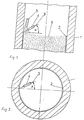
- the workpiece 1 to be plated on the inside forms a vertically standing connecting piece, in which used powder 6 fills the interior.
- the cladding 2 consists of horizontally superimposed, partially overlapping weld beads that can be applied in several layers one above the other.
- the welding powder 6 is fed through a powder feed channel 5, which ends with its mouth just above the welding area. Through him so much welding powder 6 is supplied that the welding area is completely filled.
- the welding wire 3 is fed through a welding nozzle 4, which is arranged at an angle a with respect to the horizontal and at an angle ⁇ with respect to the radius of the nozzle.
- the angles ⁇ and ⁇ are on the order of 0 to 45 ° and are determined empirically. This means that in welding tests these angles are determined from the point of view of obtaining the best quality plating possible.
- the empirical determination is necessary because these angles depend on the plating material, the size of the diameter of cylindrical workpieces to be plated and also on the type and thickness of the material to be plated. Particularly in the case of austenitic weld cladding, these angles are used to control the most favorable structure formation using delta ferrite determinations.
- Both the welding nozzle 4 and the powder feed 5 are held by a frame, not shown.
- the frame rotates both the welding nozzle 4 and the powder feed 5 in accordance with one another and continues to adjust the height offset within one revolution, so that a uniform overlap width of welding beads lying one above the other is made possible.
- the powder support can be a disc filling the cross-section when machining nozzles or a band attached to the workpiece when machining plates.
Landscapes
- Engineering & Computer Science (AREA)
- Physics & Mathematics (AREA)
- Plasma & Fusion (AREA)
- Mechanical Engineering (AREA)
- Arc Welding In General (AREA)
- Nonmetallic Welding Materials (AREA)
- Application Of Or Painting With Fluid Materials (AREA)
- Cleaning Of Streets, Tracks, Or Beaches (AREA)
Description
- Erfindung betrifft ein Verfahren zum Schweißplattieren von senkrechten Wänden, bei dem jede Plattierungslage aus übereinander angeordneten, sich gegenseitig teilweise überlappenden, horizontalen Schweißraupen gebildet wird, die mit dünnen Schweißdrähten aufgetragen werden, und das besonders an ruhenden Bauteilen, wie zum Beispiel bei Stutzeninnenplattierungen schwerer Behälterteile vorteilhaft eingesetzt werden kann.
- Es sind bereits Plattierungsverfahren durch Schweißen bekannt, bei welchen die Aufbringung des Plattierungsmaterials durch Schweißen unter Schutzgas z. B. mit Wolfram-Elektroden und mit Zusatzdraht aus dem zu plattierenden Material erfolgt.
- Bekannt ist beispielsweise eine unter Schutzgas mit vergleichsweise dünnen Draht-Abschmelzelektroden arbeitende, vollautomatische Vorrichtung zum Schweißplattieren von senkrechten Innenwänden an zylinderförmigen Körpern gemäß der US-PS 3,010,010.
- Nachteilig ist bei diesem oder ähnlichen Schweißverfahren einerseits die vergleichsweise niedrige Abschmelzleistung und andererseits die gerätetechnisch anspruchsvolle Schweißeinrichtung, bzw. die hiermit verbundene Störanfälligkeit.
- Um den Nachteil der vergleichsweise geringen Auftragsleistung auszugleichen, ist der bekannte Schweißautomat gemäß genannter US-PS mit wenigstens zwei, gegebenenfalls auch drei Schweißköpfen ausgestattet. Hierdurch wird jedoch der Nachteil des hohen gerätetechnischen Aufwandes und damit der Störanfälligkeit signifikant erhöht.
- Es sind weiterhin Schweißverfahren mit umhüllten Elektroden bekannt, bei welchen die Elektrodenführung und damit der Lagenaufbau von Hand erfolgt.
- Für diese Verfahren gilt als Nachteil ebenfalls die niedrige Abschmelzleistung, besonders aber die hohe Fehlerhäufigkeit insbesondere beim Schweißen der ersten, auf den Grundwerkstoff gelegten Plattierungslage. Dazu fallen noch die sehr hohen Kosten der manuellen Operation nachteilig ins Gewicht.
- Der Erfindung liegt die Aufgabe zugrunde, das Schweißplattieren von senkrechten Wänden derart rationalisierend und zugleich qualitativ verbessernd weiterzubilden, daß damit ein produktiveres, fehlerfreies, mechanisiertes Verfahren mit dem Ergebnis von absolut korrosionsbeständigen, dichten Schichten erzielt wird. Insbesondere sollen Fehlstellen im Auftragsgut ausgeschlossen sein, und es sollen auch solche zylindrischen Hohlkörper mit wirtschaftlichem Einsatz innen plattiert werden können, die manuell nicht zugänglich sind und demzufolge eine maschinelle Schweißung erhalten müssen. Es handelt sich dabei z. B. um fest eingeschweißte Stutzen im konventionellen und/oder nuklearen Apparatebau, an Rohrleitungen und anderen Komponenten, wie sie unter anderem im Primärkreislauf von Kernkraftwerken eingesetzt werden.
- Insbesondere in diesem Bereich der Technik soll das erfindungsgemäße Verfahren so zuverlässig arbeiten, daß das Risiko von Unterbrechungen des Schweißprozesses mit absoluter Sicherheit vermieden wird.
- Das erfindungsgemäße Schweißverfahren soll aber auch erfolgreich bei anderen Werkstücken einsetzbar sein, bei welchen die Schweißung hochwertig sein muß. Die Plattierung kann also bei dem vorstehend genannten Einsatzfall im Kernkraftwerksbereich aus hochwertigen Chrom-Nickel-Stählen bestehen, es können für die Anwendung in anderen Bereichen aber auch Materialien anderer Legierungen wie Inconel, Titan und dergleichen zum Plattieren verwendet werden.
- Diese Aufgabe wird erfindungsgemäß bei einem Verfahren der eingangs genannten Art. bei welchem jede Plattierungslage aus übereinander angeordneten, sich gegenseitig teilweise überlappenden horizontalen Schweißraupen gebildet wird dadurch gelöst, daß die Schweißraupen unter Schweißpulver durch Unterpulver-Lichtbogenschweißung aufgetragen werden, und daß als Schweißpulverhalterung durch am Werkstück angebrachte Mittel geführte, nur in Höhenrichtung nachstellbare Stützmittel verwendet werden, die keine Relativbewegung in Schweißrichtung gegenüber dem Werkstück während des Schweißens ausführen.
- Mit großem Vorteil kann dabei beim Innenplattieren von senkrecht gestellten zylindrischen Stutzen als Stützmittel für das zugeführte Schweißpulver das im Innern des Stutzens befindliche, durch Schweißen bereits eingebrachte Schweißpulver selbst verwendet werden.
- Der Vorteil dieser Schweißpulverhalterung besteht darin, daß sie nicht mit dem Schweißkopf mitläuft, also keine Relativbewegung zum Werkstück während des Schweißens ausführt und somit keine Störung des empfindlichen Schweißbades durch das Schweißpulver verursacht wird.
- Das erfindungsgemäße Verfahren ermöglicht es, besonders hochwertige Plattierungen an senkrecht stehenden Werkstücken bei hohen Fertigungsgeschwindigkeiten und geringem Aufwand herzustellen und es kann daher von einer idealen Lösung der anstehenden Probleme durch die Erfindung gesprochen werden.
- Im folgenden wird ein Ausführungsbeispiel der Erfindung anhand von Zeichnungen näher beschrieben. Es zeigen:
- Figur 1 einen Vertikalschnitt durch einen innen zu plattierenden Stutzen und
- Figur 2 einen Horizontalschnitt durch den Stutzen gemäß Figur 1.
- Gemäß Figur 1 bildet das innen zu plattierende Werkstück 1 einen senkrecht stehenden Stutzen, in welchem verbrauchtes Pulver 6 den Innenraum ausfüllt. Die Plattierung 2 besteht aus horizontal übereinanderliegenden, sich teilweise überlappenden Schweißraupen, die in mehreren Lagen übereinander aufgetragen werden können. Das Schweißpulver 6 wird durch einen Pulverzuführungskanal 5 zugeführt, welcher mit seiner Mündung dicht oberhalb des Schweißbereiches endet. Durch ihn wird soviel Schweißpulver 6 zugeführt, daß de r Schweißbereich vollständig ausgefüllt ist.
- Der Schweißdraht 3 wird durch eine Schweißdüse 4 zugeführt, die gegenüber der Horizontalen unter einem Winkel a und gegenüber dem Radius des Stutzens unter einem Winkel β angeordnet ist. Die Winkel α und ß liegen in der Größenordnung von 0 bis 45° und werden empirisch ermittelt. Das bedeutet, daß in Schweißversuchen diese Winkel unter dem Gesichtspunkt bestimmt werden, eine qualitativ bestmögliche Plattierung zu erhalten. Die empirische Ermittlung ist notwendig, da diese Winkel je nach Plattierungsmaterial, Größe des Durchmessers von zu plattierenden zylindrischen Werkstücken und auch von der Art und der Dicke des zu plattierenden Materials abhängen. Besonders bei austenitischen Schweißplattierungen wird mit diesen Winkeln die günstigste Gefügeausbildung über Deltaferritbestimmungen gesteuert.
- Sowohl die Schweißdüse 4 als auch die Pulverzuführung 5 werden von einem nicht gezeigten Gestell gehalten. Das Gestell dreht zum einen in Übereinstimmung sowohl die Schweißdüse 4 als auch die Pulverzuführung 5 und stellt weiterhin den Höhenversatz innerhalb einer Umdrehung ein, so daß eine gleichmäßige Überlappungsbreite übereinanderliegender Schweißraupen ermöglicht wird. Die Pulverstütze kann dementsprechend bei der Bearbeitung von Stutzen eine den Querschnitt ausfüllende Scheibe oder bei der Bearbeitung von Platten ein am Werkstück angebrachtes Band sein.
- Besonders vorteilhaft ist es beim Innenplattieren von Stutzen, wenn gemäß Figur 1 so viel Pulver im Stutzen zurückgelassen wird, daß im Innenbereich die Stützung des neu zugeführten Pulvers von dem bereits eingebrachten Pulver vorgenommen wird. Das Pulver 6 bildet also selbst die Pulverstütze und eine gesonderte Vorrichtung kann entfallen. Da das auf dem mit Pulver gefüllten Innenvolumen aufgelegte Pulver sich besonders leicht bewegen läßt, wird bei dieser Ausführungsform eine Störung der Bewegung der Schweißdüse 4 bzw. des durch die Schweißdüse 4 zugeführten Schweißdrahtes 3 verhindert und für den Fachmann überraschend hat sich dadurch eine besonders hohe Qualität und Störungsfreiheit der Schweißplattierung ergeben. Nicht verbrauchtes Schweißpulver innerhalb der Pulverstütze, d.h. solches Pulver, welches nicht verschlackt wurde, kann nach vollständiger Plattierung des Werkstücks 1 wieder ausgesiebt und neu verwendet werden.
- Die Ausbildung des genannten Gestells zur Führung der Pulverzuführung, der Schweißdüse und auch zur Zuführung des Schweißdrahtes 3 steht im Belieben des Konstrukteurs, kann mit bekannten Mitteln gelöst werden und auf eine entsprechende Beschreibung wird daher verzichtet.
Claims (2)
Priority Applications (2)
| Application Number | Priority Date | Filing Date | Title |
|---|---|---|---|
| AT83106136T ATE21845T1 (de) | 1982-07-06 | 1983-06-23 | Verfahren zum schweissplattieren von senkrechten waenden. |
| CA000457313A CA1219120A (en) | 1983-06-23 | 1984-06-22 | Snowplow blade with spring-loaded edge flaps |
Applications Claiming Priority (2)
| Application Number | Priority Date | Filing Date | Title |
|---|---|---|---|
| DE3225125A DE3225125C1 (de) | 1982-07-06 | 1982-07-06 | Verfahren zum Schweissplattieren von senkrechten Waenden |
| DE3225125 | 1982-07-06 |
Publications (2)
| Publication Number | Publication Date |
|---|---|
| EP0098468A1 EP0098468A1 (de) | 1984-01-18 |
| EP0098468B1 true EP0098468B1 (de) | 1986-09-03 |
Family
ID=6167680
Family Applications (1)
| Application Number | Title | Priority Date | Filing Date |
|---|---|---|---|
| EP83106136A Expired EP0098468B1 (de) | 1982-07-06 | 1983-06-23 | Verfahren zum Schweissplattieren von senkrechten Wänden |
Country Status (8)
| Country | Link |
|---|---|
| US (2) | US4539460A (de) |
| EP (1) | EP0098468B1 (de) |
| JP (1) | JPS5910472A (de) |
| AR (1) | AR230580A1 (de) |
| AT (1) | ATE21845T1 (de) |
| BR (1) | BR8303610A (de) |
| CA (1) | CA1205144A (de) |
| DE (2) | DE3225125C1 (de) |
Families Citing this family (31)
| Publication number | Priority date | Publication date | Assignee | Title |
|---|---|---|---|---|
| US4794710A (en) * | 1982-07-06 | 1989-01-03 | Haering Theodor | Snowplow blade with spring-loaded edge flaps |
| US5025577A (en) * | 1989-08-03 | 1991-06-25 | Frink America, Inc. | Adjustable one-way trip edge snow plow |
| US5048207A (en) * | 1990-03-13 | 1991-09-17 | Frink America, Inc. | Adjustable discharge wing plow |
| US5136795A (en) * | 1991-12-31 | 1992-08-11 | Ivanhoe Rosenberg | Snow plow assembly |
| US5205469A (en) * | 1992-08-13 | 1993-04-27 | Dan Capitanescu | Weld overlay device and method |
| US5437113A (en) * | 1994-01-12 | 1995-08-01 | Jones; Daniel K. | Snow plow trip cutting edge |
| DE4405924A1 (de) * | 1994-02-24 | 1995-08-31 | Johann Stahl Kessel Und Appara | Verfahren zur Fertigung von schweißplattierten Behälterböden und Formstücken |
| CA2173213C (en) * | 1994-08-02 | 2005-05-17 | Masaharu Amano | Wear-resistant overlay forming method and wear-resistant composite members |
| US5901793A (en) * | 1997-12-04 | 1999-05-11 | Case Corporation | Apparatus and method for automatically adjusting the pitch of a dozer blade |
| EP0976326B1 (de) * | 1998-07-30 | 2003-05-02 | Nihon Nohyaku Co., Ltd. | Fungizide Zusammensetzung enthaltend ein 1,2,3-Thiadiazolderivat sowie deren Verwendung |
| US6354025B1 (en) | 1998-08-04 | 2002-03-12 | Cives Corporation | Adjustable mounting arrangement for moldboard |
| US6219943B1 (en) | 1998-08-04 | 2001-04-24 | Cives Corporation | Resilient mounting arrangement for moldboard |
| FI117296B (fi) * | 2004-10-11 | 2006-08-31 | Patria Vammas Oy | Lumiauran teräelementin ripustus |
| US20070128013A1 (en) * | 2005-12-01 | 2007-06-07 | Grant Hanson | Apparatus protecting vehicle with bucket when bucket strikes fixed object |
| EP2052243A4 (de) * | 2006-07-27 | 2010-01-27 | Tasc Ltd | Hochscharfe impedanz-bilderzeugung |
| US8732988B2 (en) | 2006-11-30 | 2014-05-27 | Glenridge, Inc. | Implement with linkage assembly and work assembly wherein work assembly has dynamic skid shoe and a scraping edge |
| US8881433B2 (en) | 2006-11-30 | 2014-11-11 | Glenridge, Inc. | Implement attaching to a forward motion-producing machine for elevating an edge encountering an immovable object |
| JP4998703B2 (ja) * | 2007-01-18 | 2012-08-15 | 株式会社Ihi | 立向姿勢溶接装置の制御システム |
| US7543401B2 (en) * | 2007-08-17 | 2009-06-09 | Doug Hughes | Back drag plow |
| US8399792B2 (en) * | 2009-06-29 | 2013-03-19 | Lincoln Global, Inc. | Welding device and method |
| US8453358B2 (en) * | 2010-01-19 | 2013-06-04 | Meyer Products, Llc | Dual compression spring ram |
| US8695238B2 (en) | 2011-01-18 | 2014-04-15 | Meyer Products, Llc | Snowplow with auto angling and wireless controller |
| US9272363B2 (en) * | 2013-01-31 | 2016-03-01 | Siemens Energy, Inc. | Hybrid laser plus submerged arc or electroslag cladding of superalloys |
| PL3408454T3 (pl) | 2016-01-26 | 2024-05-13 | Usinage Pro24 Inc. | Urządzenie lemiesza zgarniającego z regulowanymi lemieszami |
| CA3023386A1 (en) | 2017-11-07 | 2019-05-07 | 1708828 Ontario Limited | Snowplow with ground contour following cutting edge and impact absorption |
| US11124935B2 (en) | 2017-11-07 | 2021-09-21 | 1708828 Ontario Limited | Snowplow with ground contour following cutting edge and impact absorption |
| CN110587139A (zh) * | 2019-10-09 | 2019-12-20 | 西安增材制造国家研究院有限公司 | 一种电弧激光同轴送丝送粉打印喷头及增材制造装置 |
| CN111545867A (zh) * | 2020-05-15 | 2020-08-18 | 徐州徐工液压件有限公司 | 一种在狭小空间内进行铜堆焊的方法 |
| EP3940145B1 (de) | 2020-07-16 | 2024-03-27 | Gestion Pihm Inc. | Kehrschaufelvorrichtung und kehrschaufelanordnung für ein fahrzeug |
| US11795641B2 (en) | 2021-03-24 | 2023-10-24 | Gestion Pihm Inc. | Sweeping blade and sweeping blade assembly for a vehicle |
| US12571175B2 (en) | 2021-08-30 | 2026-03-10 | 1708828 Ontario Ltd. | Cutting edge systems for snowplow moldboards |
Family Cites Families (19)
| Publication number | Priority date | Publication date | Assignee | Title |
|---|---|---|---|---|
| US2055291A (en) * | 1935-08-12 | 1936-09-22 | Maine Steel Products Company | Material moving apparatus |
| US2713106A (en) * | 1949-12-05 | 1955-07-12 | Chicago Bridge & Iron Co | Welding apparatus |
| FR1074114A (fr) * | 1953-02-06 | 1954-10-01 | Dispositif d'étrave pour chasse-neige et analogues | |
| US2752468A (en) * | 1954-02-16 | 1956-06-26 | Kellogg M W Co | Apparatus for field welding seams in horizontal plate |
| US2896811A (en) * | 1956-02-23 | 1959-07-28 | Babcock & Wilcox Co | Welded and bolted closure for high pressure vessel |
| DE1021103B (de) * | 1956-11-16 | 1957-12-19 | K Schweisswerk Halle Veb | Verfahren und Vorrichtung zur kontinuierlichen Unter-Schlacken-Lichtbogen-Schweissung |
| US2866078A (en) * | 1957-03-05 | 1958-12-23 | United States Steel Corp | Apparatus for welding vertical seams |
| US3035159A (en) * | 1958-08-28 | 1962-05-15 | British Oxygen Co Ltd | Electric arc welding of generally horizontal seams |
| US3010010A (en) * | 1959-01-22 | 1961-11-21 | Chicago Bridge & Iron Co | Apparatus for use in depositing weld metal as spiral, partially overlapping courses on the interior of a shell |
| US3158944A (en) * | 1963-02-20 | 1964-12-01 | Caterpillar Tractor Co | Bulldozer with resilient means for pushing operations |
| DE1515092A1 (de) * | 1964-06-10 | 1969-06-19 | Pintsch Bamag Ag | Verfahren und Vorrichtungen zum automatischen Schweissen von Behaeltern |
| DE1213461B (de) * | 1964-08-10 | 1966-03-31 | Dr Gottfried Reissinger | Raeumschar fuer Schneepfluege mit einer unten an der Raeumschar mittels einer gefederten Zwischenleiste angelenkten Raeumleiste |
| US3760882A (en) * | 1965-09-13 | 1973-09-25 | Geurts Inc | Full hydraulic earth working implement |
| US3890482A (en) * | 1970-03-24 | 1975-06-17 | Gurtler Hebert & Co Inc | Apparatus for welding together substantially vertically extending pipe sections |
| FR2148844A5 (en) * | 1971-07-30 | 1973-03-23 | Paulange Serge | Bead weld application automatically - esp for tig welding |
| US4074896A (en) * | 1976-03-29 | 1978-02-21 | Caterpillar Tractor Co. | Cushion compression struts for bulldozer blades |
| US4215809A (en) * | 1978-11-17 | 1980-08-05 | Salvatore Panzeca | Pipe welding apparatus |
| US4348574A (en) * | 1980-06-13 | 1982-09-07 | Combustion Engineering, Inc. | Flux dam for submerged arc welding |
| JPS5744470A (en) * | 1980-08-28 | 1982-03-12 | Mitsubishi Heavy Ind Ltd | Automatic build-up welding device for small-diameter deep hole part |
-
1982
- 1982-07-06 DE DE3225125A patent/DE3225125C1/de not_active Expired
-
1983
- 1983-06-23 EP EP83106136A patent/EP0098468B1/de not_active Expired
- 1983-06-23 AT AT83106136T patent/ATE21845T1/de not_active IP Right Cessation
- 1983-06-23 DE DE8383106136T patent/DE3365859D1/de not_active Expired
- 1983-06-24 JP JP58113010A patent/JPS5910472A/ja active Granted
- 1983-06-29 CA CA000431394A patent/CA1205144A/en not_active Expired
- 1983-07-05 BR BR8303610A patent/BR8303610A/pt not_active IP Right Cessation
- 1983-07-06 US US06/511,089 patent/US4539460A/en not_active Expired - Fee Related
- 1983-07-06 AR AR293533A patent/AR230580A1/es active
-
1984
- 1984-06-18 US US06/621,514 patent/US4635387A/en not_active Expired - Fee Related
Also Published As
| Publication number | Publication date |
|---|---|
| CA1205144A (en) | 1986-05-27 |
| EP0098468A1 (de) | 1984-01-18 |
| AR230580A1 (es) | 1984-05-31 |
| BR8303610A (pt) | 1984-02-14 |
| JPH0330467B2 (de) | 1991-04-30 |
| ATE21845T1 (de) | 1986-09-15 |
| JPS5910472A (ja) | 1984-01-19 |
| DE3225125C1 (de) | 1988-05-05 |
| US4539460A (en) | 1985-09-03 |
| DE3365859D1 (en) | 1986-10-09 |
| US4635387A (en) | 1987-01-13 |
Similar Documents
| Publication | Publication Date | Title |
|---|---|---|
| DE3225125C1 (de) | Verfahren zum Schweissplattieren von senkrechten Waenden | |
| DE1946909A1 (de) | Einrichtung zum Plattieren von Metalloberflaechen | |
| DE2403189B2 (de) | Verfahren zum Simulieren der Orbitalschweißung an ortsfesten Metallelementen, insbesondere Rohrkörpern, und Vorrichtung zur Durchführung des Verfahrens | |
| DE2949157A1 (de) | Vorrichtung und verfahren zum herstellen von versteiften schiffskoerpersektionen | |
| DE2257756A1 (de) | Verfahren und vorrichtung zur lokalen elektrofunkenbeschichtung von metallen und legierungen mittels einer sich drehenden elektrode | |
| DE3304201C2 (de) | Fräsvorrichtung zum Besäumen der Kanten von Blechen | |
| DE4417397C2 (de) | Befestigungselement und Vorrichtung für eine Schweißvorrichtung zum Befestigen eines solchen Elementes auf vorgelochtem Blechmaterial | |
| EP0111057A1 (de) | Verfahren und Vorrichtung zur Herstellung eines Rohrkrümmers aus Stahl | |
| DE69017393T2 (de) | Verfahren für das Ersetzen einer Heizung eines Druckausgleichgefässes in einem Kernreaktor und in einem solchen Verfahren verwendete Vorrichtung. | |
| EP0104325B1 (de) | Verfahren zum Schweissen innen plattierter zylindrischer Werkstücke | |
| DE2542081A1 (de) | Verfahren und vorrichtung zur herstellung dickwandiger werkstuecke aus stahl | |
| DE69814237T2 (de) | Nahführungsverfahren für angefaste Rohrendflächen zum Stumpfschweissen von Rohren, und Vorrichtung zur Ausführung | |
| DE3109618A1 (de) | Verfahren und vorrichtung zum verschweissen von zwei laengs ihrer raeumlichen durchdringungskurve miteinander zu verschweissenden hohlkoerpern | |
| DE2820447A1 (de) | Verfahren und einrichtung zum elektronenstrahlschweissen | |
| DE2238321C2 (de) | Unterpulver-Schweißverfahren mit abschmelzender Schweißelektrode und Vorrichtung zur Durchführung des Verfahrens | |
| DE2143085A1 (de) | Verfahren und Vorrichtung zum Bohren eines von einem Kanal abzweigenden Seitenkanals | |
| DE102016000880B3 (de) | Vorrichtung und Verfahren zum rückstandsfreien Rührreibverschweißen von Werkstücken, insbesondere von rohrartigen Strukturen, sowie Computerprogramm zur Durchführung der Verfahrensschritte | |
| EP0116663A1 (de) | Verfahren zur Dekontamination der inneren Oberfläche eines Reaktorbehälters | |
| DE2824643C2 (de) | Verfahren zur Herstellung eines Leitrings einer Wasserturbine und dessen Anwendung | |
| DE3522643C2 (de) | ||
| DE2342003C2 (de) | Verfahren und Vorrichtung zum diskontinuierlichen Einblasen von Sauerstoff in LD-Konverter | |
| DE3605494C2 (de) | ||
| DE3617979C2 (de) | Verfahren und Vorrichtung zur Beschichtung von zylindrischen Bauteilen glatter Oberfläche, insbesondere zur Wiederaufarbeitung von Stempeln | |
| DE3444820A1 (de) | Verfahren und vorrichtung zum verschweissen von mindestens zwei rohren entlang ihrer durchdringungslinie | |
| DE2151180C2 (de) | Justiervorrichtung für eine Schutzgas-Schweißbrennerdüse zum Schweißen dünnwandiger Blechgitterroste |
Legal Events
| Date | Code | Title | Description |
|---|---|---|---|
| PUAI | Public reference made under article 153(3) epc to a published international application that has entered the european phase |
Free format text: ORIGINAL CODE: 0009012 |
|
| AK | Designated contracting states |
Designated state(s): AT BE CH DE FR GB IT LI LU NL SE |
|
| 17P | Request for examination filed |
Effective date: 19840213 |
|
| GRAA | (expected) grant |
Free format text: ORIGINAL CODE: 0009210 |
|
| RAP1 | Party data changed (applicant data changed or rights of an application transferred) |
Owner name: MAN GUTEHOFFNUNGSHUETTE GMBH |
|
| AK | Designated contracting states |
Kind code of ref document: B1 Designated state(s): AT BE CH DE FR GB IT LI LU NL SE |
|
| REF | Corresponds to: |
Ref document number: 21845 Country of ref document: AT Date of ref document: 19860915 Kind code of ref document: T |
|
| ITF | It: translation for a ep patent filed | ||
| REF | Corresponds to: |
Ref document number: 3365859 Country of ref document: DE Date of ref document: 19861009 |
|
| ET | Fr: translation filed | ||
| PLBE | No opposition filed within time limit |
Free format text: ORIGINAL CODE: 0009261 |
|
| STAA | Information on the status of an ep patent application or granted ep patent |
Free format text: STATUS: NO OPPOSITION FILED WITHIN TIME LIMIT |
|
| 26N | No opposition filed | ||
| PGFP | Annual fee paid to national office [announced via postgrant information from national office to epo] |
Ref country code: CH Payment date: 19920518 Year of fee payment: 10 |
|
| PGFP | Annual fee paid to national office [announced via postgrant information from national office to epo] |
Ref country code: AT Payment date: 19920529 Year of fee payment: 10 |
|
| PGFP | Annual fee paid to national office [announced via postgrant information from national office to epo] |
Ref country code: NL Payment date: 19920630 Year of fee payment: 10 |
|
| PGFP | Annual fee paid to national office [announced via postgrant information from national office to epo] |
Ref country code: GB Payment date: 19930512 Year of fee payment: 11 Ref country code: DE Payment date: 19930512 Year of fee payment: 11 |
|
| PGFP | Annual fee paid to national office [announced via postgrant information from national office to epo] |
Ref country code: BE Payment date: 19930513 Year of fee payment: 11 |
|
| PGFP | Annual fee paid to national office [announced via postgrant information from national office to epo] |
Ref country code: LU Payment date: 19930518 Year of fee payment: 11 |
|
| PGFP | Annual fee paid to national office [announced via postgrant information from national office to epo] |
Ref country code: SE Payment date: 19930524 Year of fee payment: 11 |
|
| PGFP | Annual fee paid to national office [announced via postgrant information from national office to epo] |
Ref country code: FR Payment date: 19930525 Year of fee payment: 11 |
|
| PG25 | Lapsed in a contracting state [announced via postgrant information from national office to epo] |
Ref country code: AT Effective date: 19930623 |
|
| ITTA | It: last paid annual fee | ||
| PG25 | Lapsed in a contracting state [announced via postgrant information from national office to epo] |
Ref country code: LI Effective date: 19930630 Ref country code: CH Effective date: 19930630 |
|
| EPTA | Lu: last paid annual fee | ||
| PG25 | Lapsed in a contracting state [announced via postgrant information from national office to epo] |
Ref country code: NL Effective date: 19940101 |
|
| NLV4 | Nl: lapsed or anulled due to non-payment of the annual fee | ||
| REG | Reference to a national code |
Ref country code: CH Ref legal event code: PL |
|
| PG25 | Lapsed in a contracting state [announced via postgrant information from national office to epo] |
Ref country code: LU Free format text: LAPSE BECAUSE OF NON-PAYMENT OF DUE FEES Effective date: 19940623 Ref country code: GB Effective date: 19940623 |
|
| PG25 | Lapsed in a contracting state [announced via postgrant information from national office to epo] |
Ref country code: SE Effective date: 19940624 |
|
| PG25 | Lapsed in a contracting state [announced via postgrant information from national office to epo] |
Ref country code: BE Effective date: 19940630 |
|
| BERE | Be: lapsed |
Owner name: MAN GUTEHOFFNUNGSHUTTE G.M.B.H. Effective date: 19940630 |
|
| EUG | Se: european patent has lapsed |
Ref document number: 83106136.1 Effective date: 19950110 |
|
| GBPC | Gb: european patent ceased through non-payment of renewal fee |
Effective date: 19940623 |
|
| PG25 | Lapsed in a contracting state [announced via postgrant information from national office to epo] |
Ref country code: FR Effective date: 19950228 |
|
| PG25 | Lapsed in a contracting state [announced via postgrant information from national office to epo] |
Ref country code: DE Effective date: 19950301 |
|
| EUG | Se: european patent has lapsed |
Ref document number: 83106136.1 |
|
| REG | Reference to a national code |
Ref country code: FR Ref legal event code: ST |