EP0097927B1 - Fernsehkamera für digitale On-line-Bildauswertung - Google Patents
Fernsehkamera für digitale On-line-Bildauswertung Download PDFInfo
- Publication number
- EP0097927B1 EP0097927B1 EP83106189A EP83106189A EP0097927B1 EP 0097927 B1 EP0097927 B1 EP 0097927B1 EP 83106189 A EP83106189 A EP 83106189A EP 83106189 A EP83106189 A EP 83106189A EP 0097927 B1 EP0097927 B1 EP 0097927B1
- Authority
- EP
- European Patent Office
- Prior art keywords
- camera
- optical
- line sensor
- axis
- sensor
- Prior art date
- Legal status (The legal status is an assumption and is not a legal conclusion. Google has not performed a legal analysis and makes no representation as to the accuracy of the status listed.)
- Expired
Links
- 230000003287 optical effect Effects 0.000 claims description 43
- 230000008878 coupling Effects 0.000 claims description 14
- 238000010168 coupling process Methods 0.000 claims description 14
- 238000005859 coupling reaction Methods 0.000 claims description 14
- 238000012634 optical imaging Methods 0.000 claims description 11
- 238000003384 imaging method Methods 0.000 claims description 9
- 238000005286 illumination Methods 0.000 claims description 4
- 230000004913 activation Effects 0.000 claims 1
- 230000005855 radiation Effects 0.000 claims 1
- 230000005540 biological transmission Effects 0.000 description 5
- 238000001816 cooling Methods 0.000 description 3
- 239000000835 fiber Substances 0.000 description 2
- 230000004907 flux Effects 0.000 description 2
- 238000007781 pre-processing Methods 0.000 description 2
- 230000035945 sensitivity Effects 0.000 description 2
- 230000001133 acceleration Effects 0.000 description 1
- 239000000498 cooling water Substances 0.000 description 1
- 238000010586 diagram Methods 0.000 description 1
- 238000005516 engineering process Methods 0.000 description 1
- 238000011156 evaluation Methods 0.000 description 1
- 229910052736 halogen Inorganic materials 0.000 description 1
- 230000006698 induction Effects 0.000 description 1
- 238000009434 installation Methods 0.000 description 1
- 239000002184 metal Substances 0.000 description 1
- 239000013307 optical fiber Substances 0.000 description 1
- 238000003909 pattern recognition Methods 0.000 description 1
- 230000002093 peripheral effect Effects 0.000 description 1
- 238000005070 sampling Methods 0.000 description 1
- 230000001360 synchronised effect Effects 0.000 description 1
- 230000009897 systematic effect Effects 0.000 description 1
Images

Classifications
-
- H—ELECTRICITY
- H04—ELECTRIC COMMUNICATION TECHNIQUE
- H04N—PICTORIAL COMMUNICATION, e.g. TELEVISION
- H04N3/00—Scanning details of television systems; Combination thereof with generation of supply voltages
- H04N3/02—Scanning details of television systems; Combination thereof with generation of supply voltages by optical-mechanical means only
- H04N3/08—Scanning details of television systems; Combination thereof with generation of supply voltages by optical-mechanical means only having a moving reflector
-
- H—ELECTRICITY
- H04—ELECTRIC COMMUNICATION TECHNIQUE
- H04N—PICTORIAL COMMUNICATION, e.g. TELEVISION
- H04N23/00—Cameras or camera modules comprising electronic image sensors; Control thereof
- H04N23/50—Constructional details
- H04N23/555—Constructional details for picking-up images in sites, inaccessible due to their dimensions or hazardous conditions, e.g. endoscopes or borescopes
-
- H—ELECTRICITY
- H04—ELECTRIC COMMUNICATION TECHNIQUE
- H04N—PICTORIAL COMMUNICATION, e.g. TELEVISION
- H04N23/00—Cameras or camera modules comprising electronic image sensors; Control thereof
- H04N23/58—Means for changing the camera field of view without moving the camera body, e.g. nutating or panning of optics or image sensors
Definitions
- the invention relates to a television camera according to the preamble of claim 1.
- the present invention is based on the object of creating an on-line television camera with a line sensor which is advantageous for a wider range of applications.
- this object is achieved with a television camera of the type specified at the outset, which is characterized in that, in order to detect an optical object distributed around a panorama axis and to generate the relative movement, the line sensor can be driven in rotation about the optical image of the panorama axis and is arranged in such a way that the sensor surfaces are in the optical images of axially offset elements of the object area and when the line sensor rotates, each sensor surface defines a scanning line that is rotationally symmetrical to the panorama axis, and that the output of the line sensor is connected to the operating circuit via a multi-channel, contactless optical rotary coupling.
- the television camera according to the invention enables the generation of on-line panorama television images with a large picture angle in a very simple manner with simple and precise geometric assignment between object and image.
- the components of the camera can be made very robust and small, so that even relatively narrow hollow bodies can be examined. Compared to these very important advantages, the need to decouple the signals supplied by the line sensor via a rotary coupling is negligible.
- a contactless, multi-channel optical rotary coupling is provided in the television camera according to the invention, which can transmit high signal bandwidths without interference and thus enables the high processing speeds required and desired for online image evaluation.
- the television camera according to the invention also offers decisive advantages over other previously known on-line television cameras in which the image area (the optical image) is scanned with the aid of an energy beam.
- the facilities required for this, in particular high vacuum parts, are considerably more complex, voluminous and mechanically sensitive than the parts of the television camera according to the invention.
- the scanning principle used in the camera according to the invention and the resulting decisive advantages with regard to the geometric accuracy of the image have not been realized in prior art television cameras with energy beam scanning and, in principle, cannot be achieved either.
- one could also reduce the geometric errors in energy beam scanning by using a conventional television camera dimmed down to a slot such a solution would be considerably more complex than the technology with a stationary conventional television camera with energy beam scanning.
- An endoscope is also known (DE-OS 26 33 742), in which an image of an object to be viewed is generated by an optical system on a solid-state image pickup element and this is controlled to scan the image and to generate corresponding electrical signals.
- the image pickup element not only captures one line of the image, but the entire image, and the image pickup element is not rotated.
- a picture angle comparable to panorama pictures cannot be achieved in this way, rather the detectable picture angle depends on the optical system. There is no direct scanning of a panorama free of geometric errors.
- the optical imaging system is preferably arranged protected in a camera head.
- the camera head can be designed freely, especially with a long and relatively thin tube, so that the camera is particularly well suited for endoscopic applications.
- the camera head is preferably rotatable about the panorama axis, and the optical imaging system and the line sensor are fixedly arranged in the camera head. With this design, the rotary drive can be provided on the outside and made simpler.
- the camera will normally scan several object areas in succession, for example by moving the camera or the camera head mentioned in the direction of the panorama axis.
- the camera head mentioned can be mounted on the camera so that it can move axially in the direction of the panorama axis.
- This has the advantage that the camera can be fixed in a machine; the movements required to scan an elongated hollow body are then carried out solely by the camera head.
- the scanning of the object in the direction of the panorama axis can take place evenly during the rotation of the optical imaging system, - then a continuous screw band is scanned as the object area - or batchwise between all-round scans with a fixed axial position, - then the scanned object areas are circular cylindrical surfaces.
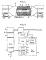
- FIGS 1 to 3 schematically explain a television camera for digital online image processing.
- the camera is designed to capture an optical object distributed around a panorama axis 1.
- the camera forms part of an endoscope and is used to capture the inside of a hollow body 3, the cavity 5 of which is rotationally symmetrical about an object axis 7 in the case shown.
- the inside of the hollow body 3 forms the optical object 9.
- the panorama axis 1 defined by the camera is expediently arranged coaxially with the object axis 7, as shown.
- the camera has an optical imaging system 11, which images an object area 13 captured by the camera, here part of the inner surface of the hollow body 5, into an image area 15 that can be scanned element by element.
- the camera has. an operating circuit 17 which generates video signals from the signals obtained during sampling; these in turn can be used for generating a television picture or for processing in computers and the like.
- the imaging system 11 has an imaging axis 19 which is arranged coaxially with the panorama axis 1, and the optical image 21 of the panorama axis lies coaxially with the panorama axis 1. This arrangement is very space-saving and facilitates the installation of the most important parts of the camera in a narrow tube suitable for endoscopic purposes.
- a line-shaped receiving surface of a line sensor 23 which can be driven in rotation about the panorama axis 1 and which is composed of sensor surfaces 25 of a number of optical-electrical converters 27 in such a way that the sensor surfaces in the (depending on the design of the optical imaging system, if desired, enlarged or reduced) optical ones
- There are images of imaginary elements 29 of the object region 13 which are axially offset from one another and each transducer sensor surface 25 defines a scanning line, for example 31, on the object 11 that is rotationally symmetrical to the panorama axis 1 when the line sensor 23 rotates about the optical image 21 of the panorama axis 1.
- the line sensor contains processing (not shown in detail) circuit which ensures that when an interrogation signal is fed in, the output signals of the individual converters 27 are called up in succession and a carrier frequency of 10 MHz, for example, is modulated.
- the high-frequency primary image signal generated in this way like the retrieval signals and other control and synchronization signals - is passed via a multi-channel, non-contact optical rotary coupling 33 and reaches the operating circuit 17, which in turn generates video signals and is connected to a downstream bit processing system (not shown) provides.
- the detected object area 13 is at a relatively small angle about the optical axis 19, i.e. H. a narrow strip-shaped surface piece with orientation parallel to the optical axis 19, limited, for example by the dimension of the line sensor and the imaging scale, and the imaging rays are deflected by an optical deflection device 37, here in the form of a deflection prism, through 90 ° into the optical axis 19 distracted.
- an optical deflection device 37 here in the form of a deflection prism
- the setting means has, for example, a front lens 39 adjustable along the optical axis 19 known in optics and therefore not shown here for the sake of simplicity.
- the line sensor 23 and the optical imaging system 11 are arranged protected in a camera head 41, specifically in a relatively narrow tube 43 belonging to the camera head 41, which is particularly suitable for endoscopic purposes.
- the imaging beam path passes from the detected object area 13 through the deflecting prism 37 forming the entrance hatch.
- the camera head 41 is mounted on a camera body (not shown) so that it can be driven in rotation about the panorama axis 1, and the line sensor 23 is fixedly arranged in the camera head 41.
- the rotary drive 44 (not shown in FIG. 1) (FIG. 5) can be made robust and easily accessible. It is easily possible to mount the camera head 41 on the camera body, not shown, in an axially movable manner. This is advantageous for industrial applications because the camera body (not shown) can then be arranged firmly on a machine.
- a coding disk 45 is indicated as a simple embodiment of such a synchronizing device, which is attached to the rotatable camera head 41 and is read by a synchronous sensor 47 which is not rotated.
- the generation of the video signals can also be restricted to selected sub-areas of the panorama captured by the camera.
- the transducers of the line sensor can be individually adjustable in their sensitivities. Although this measure is fundamentally simple, it can require considerable effort if a high resolution is desired and a correspondingly large number of transducers per unit length of the line sensor is provided.
- line sensors are known in which there are approximately one thousand transducers in a line of 1 cm in length. This is also necessary for good image resolution. It is therefore usually easier to illuminate the object area with an illuminating device in which the illuminance distribution generated in the object area can be changed.
- the lighting device should be adjustable such that the signals of all transducers 27 are the same in the case of a structureless object area 13. Then it is ensured that a brightness structure which is represented in the generated video signals only results from irregularities in the surface of the object.
- the input power available per converter is only very small. In order to achieve a sufficiently large signal-to-noise ratio and to ensure a high contrast of a video image generated from the video signals, one must work with high illuminance.
- a powerful lamp 49 for example a tungsten-halogen lamp or a gas discharge lamp, is arranged at a location distant from the narrow tube 43 where there is sufficient space available.
- a condenser 51 detects as large a part as possible of the luminous flux supplied by the lamp and introduces it into a coupling prism 53 at the beginning of an optical fiber cable 55.
- the luminous flux is guided to the object region 13 via a coupling-out prism 57 and a cylindrical lens 59.
- the cylindrical lens 59 is arranged close to the deflection device 37.
- the illuminated area piece is only slightly larger than the object area 13 to be imaged.
- An optical gradient filter 61 is arranged in the illumination beam path and is designed such that the signals supplied by the optical-electrical transducers 27 are the same size in the case of a structureless object area.
- a high signal-to-noise ratio can also ner can be achieved by cooling the optical-electrical converter 27.
- a cooling device 63 is provided in the illustrated embodiment.
- This contains a whip module 65 which has a cold side which is thermally conductively connected to the line sensor 23 via a metal block 67 and a warm side which is thermally conductively connected to an adjacent heat sink 71.
- the heat sink 71 can act solely by its heat capacity or in turn can be cooled by a stationary outer cooling jacket (not shown) which surrounds it at a short distance and which is cooled in some way, for example by means of cooling water.
- the adjoining rooms, but in particular also the entire camera head 41 can be sealed to the outside and filled with a dry gas.
- the power supply for the lighting device and the Peltier module 65 takes place by means not shown, for example slip rings or induction coils.
- the read-out signals for the line sensor 23 and the primary image signals supplied by the line sensor are, if necessary after preprocessing in the camera head 41, transmitted to and from the operating circuit 17 via the multichannel non-contact optical rotary coupling 33.
- This clutch 33 contains two clutch halves 75, 77 which are rotated relative to one another.
- Control signals come from the operating circuit 17 to the line sensor 23 and to a sequence control 79 for the rotary drive 44.
- the latter consists of a motor 81, a transmission 83, a clutch 85 and brakes 87.
- the rotary coupling is designed as an optical coupling with a plurality of concentric light channels 89, 91, 93 and 95.
- Optical transmitters are arranged at the inputs of the light channels. 4 only such a transmitter 97 and a drive amplifier 99 for the light channel 91 are shown.
- the light channels are provided at their outputs with optical-electrical receivers and assigned amplifiers.
- the optical transmitters are preferably designed as laser diodes or light emitting diodes for visible or ultra-red light.
- the optical receivers can have, for example, an avalanche or p-i-n photodiode as an effective element. 4, only one receiver 101 is indicated.
- the first light channel 89 is arranged in a central divided tube 103.
- An optical lighting system consisting of a condenser 105 and a field lens 107 ensures uniform illumination of the associated receiver (not shown).
- the central tube 103 is made light-tight by panels (not shown) or the like.
- the other light channels or transmission paths each contain a split fiber ring bundle with circular end faces in sleeves.
- the associated optical transmitters and receivers for example the transmitter 97 or receiver 101 shown in FIG. 4, are arranged together with the associated coupling-in and coupling-out optics and amplifiers in plug-in sleeves, for example 109, 111. In this way, the direction of transmission can be easily reversed.
- the light channels are shielded from one another in order to prevent crosstalk as much as possible.
- the pairs of end faces belonging to different channels are offset from one another in the axial direction, for example the pairs 113, 115 and 117, 119 shown in FIG. 4.
- the crosstalk attenuation is further improved by the fact that the optical transmitters of adjacent channels are designed to generate different light carrier frequencies.
- the light channels are connected to the operating circuit via optical filters. This further improves crosstalk attenuation.
- channels 89 and 91 are alternately populated like channels 89 and 91. In this way, neighboring transmission channels are double protected against crosstalk.
Landscapes
- Engineering & Computer Science (AREA)
- Multimedia (AREA)
- Signal Processing (AREA)
- Studio Devices (AREA)
- Instruments For Viewing The Inside Of Hollow Bodies (AREA)
- Stereoscopic And Panoramic Photography (AREA)
- Closed-Circuit Television Systems (AREA)
- Endoscopes (AREA)
Applications Claiming Priority (2)
| Application Number | Priority Date | Filing Date | Title |
|---|---|---|---|
| DE3223971 | 1982-06-26 | ||
| DE3223971A DE3223971C2 (de) | 1982-06-26 | 1982-06-26 | Fernsehkamera für digitale On-line-Bildauswertung |
Publications (3)
| Publication Number | Publication Date |
|---|---|
| EP0097927A2 EP0097927A2 (de) | 1984-01-11 |
| EP0097927A3 EP0097927A3 (en) | 1985-05-22 |
| EP0097927B1 true EP0097927B1 (de) | 1987-09-30 |
Family
ID=6166972
Family Applications (1)
| Application Number | Title | Priority Date | Filing Date |
|---|---|---|---|
| EP83106189A Expired EP0097927B1 (de) | 1982-06-26 | 1983-06-24 | Fernsehkamera für digitale On-line-Bildauswertung |
Country Status (3)
| Country | Link |
|---|---|
| EP (1) | EP0097927B1 (enExample) |
| JP (1) | JPS5913234A (enExample) |
| DE (1) | DE3223971C2 (enExample) |
Families Citing this family (4)
| Publication number | Priority date | Publication date | Assignee | Title |
|---|---|---|---|---|
| DE3733593A1 (de) * | 1987-10-05 | 1989-04-20 | Thyssen Industrie | Vorrichtung zur aufnahme eines gegenstands, insbesondere zwecks dessen wiedergabe auf dem bildschirm eines bildschirmgeraets |
| CA2194002A1 (fr) * | 1996-12-24 | 1998-06-24 | Pierre Girard | Camera electronique panoramique |
| DE19738827C1 (de) * | 1997-09-05 | 1999-07-15 | Daimler Chrysler Ag | Optische Prüfstation und Verfahren zur optischen Prüfung von Hohlkörpern, insbesondere von Zylindern in Brennkraftmaschinen |
| WO2004056088A1 (de) * | 2002-12-18 | 2004-07-01 | Siemens Aktiengesellschaft | Kamerasystem mit bilddrehung, insbesondere für medizinische anwendungen |
Family Cites Families (4)
| Publication number | Priority date | Publication date | Assignee | Title |
|---|---|---|---|---|
| DE2633742C2 (de) * | 1975-07-28 | 1984-04-19 | Olympus Optical Co., Ltd., Tokio/Tokyo | Endoskop |
| DE2716789A1 (de) * | 1977-04-15 | 1978-10-19 | Spinner Georg | Drehkupplung zur uebertragung von signalen |
| SE439377B (sv) * | 1978-07-26 | 1985-06-10 | Hitachi Ltd | Anordning for optisk inspektion av rorledningar |
| DE3133326C2 (de) * | 1981-08-22 | 1983-07-28 | Licentia Patent-Verwaltungs-Gmbh, 6000 Frankfurt | "Tragbares Wärmebildgerät" |
-
1982
- 1982-06-26 DE DE3223971A patent/DE3223971C2/de not_active Expired
-
1983
- 1983-06-24 EP EP83106189A patent/EP0097927B1/de not_active Expired
- 1983-06-27 JP JP58116824A patent/JPS5913234A/ja active Granted
Also Published As
| Publication number | Publication date |
|---|---|
| DE3223971C2 (de) | 1984-06-14 |
| JPS5913234A (ja) | 1984-01-24 |
| JPH0552485B2 (enExample) | 1993-08-05 |
| DE3223971A1 (de) | 1984-01-19 |
| EP0097927A2 (de) | 1984-01-11 |
| EP0097927A3 (en) | 1985-05-22 |
Similar Documents
| Publication | Publication Date | Title |
|---|---|---|
| DE3410401C2 (de) | Elektro-optische Bildabtaster-Anordnung | |
| DE2331012C3 (de) | Vorrichtung zum Abtasten der von einer Szene ausgehenden Strahlungsenergie | |
| DE3586855T2 (de) | Sequentielle farblichtquellen fuer endoskope des typs, die ein festkoerperbildaufnahmeelement aufweisen. | |
| DE69112320T2 (de) | Verfahren und Vorrichtung zur optischen Abtastung. | |
| EP1074214B1 (de) | Gerät zur Augenuntersuchung mit einer Scheimpflugkamera und einem Spaltprojektor | |
| DE3638367C2 (de) | Elektronisches Endoskopiegerät | |
| DE4218692B4 (de) | Einrichtung zum Übertragen von Daten zwischen einem rotierenden und einem stationären Teil | |
| US4532544A (en) | Line-scan panoramic camera | |
| DE3688701T2 (de) | Infrarot-Abtastvorrichtung für stereoskopische Bilderzeugung. | |
| DE3242716C2 (de) | Optisches Bildbeobachtungsgerät | |
| DE2219954A1 (de) | Optische Abtastvorrichtung | |
| DE1933719A1 (de) | Einrichtung zur Lagebestimmung von Werkstuecken | |
| EP0097927B1 (de) | Fernsehkamera für digitale On-line-Bildauswertung | |
| DE2848325A1 (de) | Waermebildgeraet zum erfassen und erkennen eines waermeziels | |
| EP0115267B1 (de) | Abbildungssystem | |
| DE69227355T2 (de) | Vorrichtung für vergrösserte beobachtung | |
| DE3407486C2 (de) | Vorrichtung zum optischen Abtasten und/oder Aufbau eines Bildes | |
| CH670540A5 (enExample) | ||
| EP0156124A2 (de) | Vorrichtung zum Übertragung von Lichtsignalen zwischen zwei Bauteilen | |
| DE19921734C2 (de) | Anordnung und Verfahren zur photoelektrischen Panoramaaufnahme | |
| DE2611106B2 (de) | Vorrichtung zur erkennung der schaerfe eines optischen bildes | |
| DE10050890A1 (de) | Verfahren und Vorrichtung zur optischen Übertragung von Informationen zwischen zwei in Bezug zueinander rotierenden Systemen | |
| DE3530939A1 (de) | Optische datenuebertragungsvorrichtung | |
| DE3332909A1 (de) | Anordnung zum beleuchten einer zeile eines informationstraegers | |
| EP0372101A1 (de) | Röntgendiagnostikanlage mit einer Bildverstärker-Fernsehkette |
Legal Events
| Date | Code | Title | Description |
|---|---|---|---|
| PUAI | Public reference made under article 153(3) epc to a published international application that has entered the european phase |
Free format text: ORIGINAL CODE: 0009012 |
|
| AK | Designated contracting states |
Designated state(s): CH FR GB IT LI SE |
|
| PUAL | Search report despatched |
Free format text: ORIGINAL CODE: 0009013 |
|
| AK | Designated contracting states |
Designated state(s): CH FR GB IT LI SE |
|
| 17P | Request for examination filed |
Effective date: 19851009 |
|
| 17Q | First examination report despatched |
Effective date: 19870120 |
|
| GRAA | (expected) grant |
Free format text: ORIGINAL CODE: 0009210 |
|
| AK | Designated contracting states |
Kind code of ref document: B1 Designated state(s): CH FR GB IT LI SE |
|
| ET | Fr: translation filed | ||
| ITF | It: translation for a ep patent filed | ||
| GBT | Gb: translation of ep patent filed (gb section 77(6)(a)/1977) | ||
| PLBE | No opposition filed within time limit |
Free format text: ORIGINAL CODE: 0009261 |
|
| STAA | Information on the status of an ep patent application or granted ep patent |
Free format text: STATUS: NO OPPOSITION FILED WITHIN TIME LIMIT |
|
| 26N | No opposition filed | ||
| ITTA | It: last paid annual fee | ||
| EAL | Se: european patent in force in sweden |
Ref document number: 83106189.0 |
|
| REG | Reference to a national code |
Ref country code: GB Ref legal event code: IF02 |
|
| PGFP | Annual fee paid to national office [announced via postgrant information from national office to epo] |
Ref country code: SE Payment date: 20020617 Year of fee payment: 20 |
|
| PGFP | Annual fee paid to national office [announced via postgrant information from national office to epo] |
Ref country code: GB Payment date: 20020619 Year of fee payment: 20 |
|
| PGFP | Annual fee paid to national office [announced via postgrant information from national office to epo] |
Ref country code: FR Payment date: 20020628 Year of fee payment: 20 Ref country code: CH Payment date: 20020628 Year of fee payment: 20 |
|
| PG25 | Lapsed in a contracting state [announced via postgrant information from national office to epo] |
Ref country code: LI Free format text: LAPSE BECAUSE OF EXPIRATION OF PROTECTION Effective date: 20030623 Ref country code: GB Free format text: LAPSE BECAUSE OF EXPIRATION OF PROTECTION Effective date: 20030623 Ref country code: CH Free format text: LAPSE BECAUSE OF EXPIRATION OF PROTECTION Effective date: 20030623 |
|
| REG | Reference to a national code |
Ref country code: GB Ref legal event code: PE20 |
|
| EUG | Se: european patent has lapsed | ||
| REG | Reference to a national code |
Ref country code: CH Ref legal event code: PL |