EP0097601A2 - Form mit beweglichen Elementen zum Herstellen von Konstruktionsblöcken oder Strecksteinen mit einer Isolierschicht auf mindestens einer Seite - Google Patents
Form mit beweglichen Elementen zum Herstellen von Konstruktionsblöcken oder Strecksteinen mit einer Isolierschicht auf mindestens einer Seite Download PDFInfo
- Publication number
- EP0097601A2 EP0097601A2 EP83420093A EP83420093A EP0097601A2 EP 0097601 A2 EP0097601 A2 EP 0097601A2 EP 83420093 A EP83420093 A EP 83420093A EP 83420093 A EP83420093 A EP 83420093A EP 0097601 A2 EP0097601 A2 EP 0097601A2
- Authority
- EP
- European Patent Office
- Prior art keywords
- blocks
- mold
- walls
- faces
- molding
- Prior art date
- Legal status (The legal status is an assumption and is not a legal conclusion. Google has not performed a legal analysis and makes no representation as to the accuracy of the status listed.)
- Withdrawn
Links
Images
Classifications
-
- B—PERFORMING OPERATIONS; TRANSPORTING
- B28—WORKING CEMENT, CLAY, OR STONE
- B28B—SHAPING CLAY OR OTHER CERAMIC COMPOSITIONS; SHAPING SLAG; SHAPING MIXTURES CONTAINING CEMENTITIOUS MATERIAL, e.g. PLASTER
- B28B7/00—Moulds; Cores; Mandrels
- B28B7/0088—Moulds in which at least one surface of the moulded article serves as mould surface, e.g. moulding articles on or against a previously shaped article, between previously shaped articles
-
- B—PERFORMING OPERATIONS; TRANSPORTING
- B28—WORKING CEMENT, CLAY, OR STONE
- B28B—SHAPING CLAY OR OTHER CERAMIC COMPOSITIONS; SHAPING SLAG; SHAPING MIXTURES CONTAINING CEMENTITIOUS MATERIAL, e.g. PLASTER
- B28B1/00—Producing shaped prefabricated articles from the material
- B28B1/008—Producing shaped prefabricated articles from the material made from two or more materials having different characteristics or properties
-
- B—PERFORMING OPERATIONS; TRANSPORTING
- B28—WORKING CEMENT, CLAY, OR STONE
- B28B—SHAPING CLAY OR OTHER CERAMIC COMPOSITIONS; SHAPING SLAG; SHAPING MIXTURES CONTAINING CEMENTITIOUS MATERIAL, e.g. PLASTER
- B28B7/00—Moulds; Cores; Mandrels
- B28B7/02—Moulds with adjustable parts specially for modifying at will the dimensions or form of the moulded article
-
- B—PERFORMING OPERATIONS; TRANSPORTING
- B28—WORKING CEMENT, CLAY, OR STONE
- B28B—SHAPING CLAY OR OTHER CERAMIC COMPOSITIONS; SHAPING SLAG; SHAPING MIXTURES CONTAINING CEMENTITIOUS MATERIAL, e.g. PLASTER
- B28B7/00—Moulds; Cores; Mandrels
- B28B7/24—Unitary mould structures with a plurality of moulding spaces, e.g. moulds divided into multiple moulding spaces by integratable partitions, mould part structures providing a number of moulding spaces in mutual co-operation
- B28B7/241—Detachable assemblies of mould parts providing only in mutual co-operation a number of complete moulding spaces
Definitions
- the invention relates to a mold with movable elements intended for manufacturing building blocks or blocks with an insulating layer on at least one face.
- Concrete block blocks or other elements made of materials used in the building industry are generally obtained by molding in one or more single or multiple molds, most often integrated in an installation and operating in automatic cycle.
- an insulating layer is molded on one or more faces, at the same time as the blocks or concrete blocks, so that the walls or partitions constructed with these blocks are directly covered externally by a layer of insulating material, in order to ensure, in particular within the framework of existing standards, good thermal and acoustic insulation.
- the present invention as characterized in the claims, makes it possible to manufacture at the same time, in the same mold and in the best conditions of execution and productivity, the resistant load-bearing part or block and the insulating part or layer, being observed that this insulating layer must be formed on at least one face of the block and generally two consecutive faces. Particular attention has been paid to the best contact and the best adhesion and bond between the material of the block itself and the material of the insulating layer.
- the mold in accordance with the present invention, is remarkable in that it has on at least one of its faces and more generally two consecutive faces, one or more walls movable in translation to pass from an advanced position corresponding to the molding of the resistant load-bearing part, in a retracted position corresponding to the molding of the insulating layer.
- the mold has perpendicular to the movable walls, flaps intended to close the filling spaces in insulating material, during the molding of the resistant load-bearing part, by being flush with the upper face of the mold, and to retract during filling the insulating layer.
- the mold is designed to mold four blocks comprising a resistant load-bearing part and an insulating layer, along two consecutive faces; to this end, the mold has in its middle part, two perpendicular partitions in the shape of a cross to serve as a fixed support for two consecutive faces of the blocks, pairs of opposite movable walls two by two to close the filling space of the load-bearing part, and pairs of retractable shutters for closing the filling spaces in insulating material.
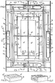
- the mold comprises, in a fixed part, a carcass or frame 1 made of sheet metal or similar elements having peripheral walls 1a - 1b, lateral faces 1c for fixing to the means of displacement of the frame, a central cross partition 1d delimiting two perpendicular reference faces for each block of material to be produced and plates le arranged parallel to one of the central partitions and limited to the angle of the blocks which is located between two faces to be covered by the insulation.
- the mold has a set of 8 walls 2, 3, 4, 5, intended to close the space or volume between the central partition and these mobile walls.
- these walls are connected to flanges 6 perpendicular to said walls and extending towards the outside of the mold.
- These soles are themselves connected two by two for the same side of the mold, with crosspieces 7, 8, extending up to near the peripheral walls of the mold; the parallel and opposite crosspieces 7 being, for example, located above the parallel and opposite crosspieces 8.
- each crosspiece is connected to two aligned movable walls ( Figure 1).
- the crosspieces 7 and 8 must be moved between two limit positions according to which the movable walls 2, 3, 4, 5 delimit either the space A corresponding to the molding of the resistant load-bearing part, or the space A + C corresponding to the molding of the strong load-bearing part plus the molding of the insulating layer.
- a hydraulic control is implemented in the form of double-acting cylinders 9, which are mounted at each end of the crosspieces 7, 8.
- These jacks have a body or cylinder 9a articulated at one end of the crosspiece, while that the rod 9b of the piston 9c is articulated on one end of the opposite cross-member.
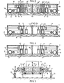
- the movable walls 2, 3, 4, 5 can thus pass from an advanced position (FIGS. 3 and 4) corresponding to the molding of the resistant load-bearing part B1 of the blocks B, to a retracted position (FIGS. 1 and 2) corresponding to the molding of the insulating layer B2 of the blocks (displacements represented by the arrows f).
- flaps 12 suitably guided and connected to cylinders 13 double acting, placed on the flanges 6.
- the flaps 12 are outcrop of the upper face 1f of the mold in the advanced position of the movable walls, while they are retracted to pass under this face when the movable walls are in the retracted position (FIG. 2).
- the mold is placed on a wooden tray P for example, with its movable walls in the advanced position and the flaps in flush position with the upper face of the mold.
- the upper plate T1 is activated by a vibrating table T on which the wooden plate is placed (FIG. 5) and the spaces A are filled with the material constituting the resistant load-bearing part B1.
- the resistant or carrier material although already hardened (therefore holding well when the walls are moved back) is still malleable enough to allow good homogenization with the insulating material.
- This interpenetration of materials is also reinforced by compression under vibration using a pestle 14 acting on the upper face of the mold ( Figure 5).
- the pestle When the molded materials are sufficiently compressed, the pestle is stopped in the support position on the mold and it is removed from the mold by lifting the mold using lateral jacks 15 for example, attached to the faces 1c of the mold (FIG. 5). .
- FIGS. 6 and 7 show two non-limiting examples of blocks or concrete blocks produced according to the invention, namely: a corner block B and a lintel D which has two consecutive faces coated with insulating material.
- the molding operation at the same time, of the carrier part and the insulating layer is preferably integrated into an installation with supply of trays and materials, automatic evacuation and transfer, according to a determined cycle.
Landscapes
- Engineering & Computer Science (AREA)
- Manufacturing & Machinery (AREA)
- Chemical & Material Sciences (AREA)
- Ceramic Engineering (AREA)
- Mechanical Engineering (AREA)
- Moulds For Moulding Plastics Or The Like (AREA)
- Press-Shaping Or Shaping Using Conveyers (AREA)
- Adjustable Resistors (AREA)
- Devices For Post-Treatments, Processing, Supply, Discharge, And Other Processes (AREA)
- Manufacture Of Motors, Generators (AREA)
Applications Claiming Priority (2)
| Application Number | Priority Date | Filing Date | Title |
|---|---|---|---|
| FR8211125 | 1982-06-22 | ||
| FR8211125A FR2528756A1 (fr) | 1982-06-22 | 1982-06-22 | Moule a elements mobiles destines a fabriquer des blocs ou parpaings de construction presentant une couche isolante sur au moins une face |
Publications (2)
| Publication Number | Publication Date |
|---|---|
| EP0097601A2 true EP0097601A2 (de) | 1984-01-04 |
| EP0097601A3 EP0097601A3 (de) | 1984-12-27 |
Family
ID=9275385
Family Applications (1)
| Application Number | Title | Priority Date | Filing Date |
|---|---|---|---|
| EP83420093A Withdrawn EP0097601A3 (de) | 1982-06-22 | 1983-06-06 | Form mit beweglichen Elementen zum Herstellen von Konstruktionsblöcken oder Strecksteinen mit einer Isolierschicht auf mindestens einer Seite |
Country Status (4)
| Country | Link |
|---|---|
| EP (1) | EP0097601A3 (de) |
| DE (1) | DE97601T1 (de) |
| ES (1) | ES523406A0 (de) |
| FR (1) | FR2528756A1 (de) |
Family Cites Families (3)
| Publication number | Priority date | Publication date | Assignee | Title |
|---|---|---|---|---|
| GB201306A (en) * | 1922-05-17 | 1923-08-02 | John Ernest Jones | An improved adjustable mould for manufacturing concrete blocks, slabs, quoins, and the like |
| US1631901A (en) * | 1926-09-11 | 1927-06-07 | William A Threadgill | Concrete-block mold |
| DE592745C (de) * | 1929-05-07 | 1934-02-14 | Hermann Ulrich Maschinenfabrik | Verfahren und Form zur Herstellung eines aus mindestens zwei verschiedenen Stoffen bestehenden Kunststeins |
-
1982
- 1982-06-22 FR FR8211125A patent/FR2528756A1/fr active Granted
-
1983
- 1983-06-06 DE DE1983420093 patent/DE97601T1/de active Pending
- 1983-06-06 EP EP83420093A patent/EP0097601A3/de not_active Withdrawn
- 1983-06-18 ES ES523406A patent/ES523406A0/es active Granted
Also Published As
| Publication number | Publication date |
|---|---|
| FR2528756A1 (fr) | 1983-12-23 |
| DE97601T1 (de) | 1985-09-12 |
| FR2528756B3 (de) | 1985-05-10 |
| ES8404902A1 (es) | 1984-05-16 |
| ES523406A0 (es) | 1984-05-16 |
| EP0097601A3 (de) | 1984-12-27 |
Similar Documents
| Publication | Publication Date | Title |
|---|---|---|
| FR2950640A1 (fr) | Procede pour la realisation d'un batiment a ossature bois prefabrique et batiment ainsi obtenu | |
| EP0097601A2 (de) | Form mit beweglichen Elementen zum Herstellen von Konstruktionsblöcken oder Strecksteinen mit einer Isolierschicht auf mindestens einer Seite | |
| FR2539801A1 (fr) | Procede de finition en particulier au niveau des ouvertures formees dans le gros oeuvre de batiments et elements prefabriques pour la mise en oeuvre de ce procede | |
| CN213198103U (zh) | 一种混凝土构件模具 | |
| EP0251878B1 (de) | Verfahren und Vorrichtung zum Formen von Gehäusen, Kästen oder Schränken, und erhaltenes Gehäuse | |
| FR2507647A1 (fr) | Panneau de construction prefabrique et procede pour la realisation d'un tel panneau | |
| FR2584758A1 (fr) | Profile metallique pour element prefabrique en beton a ossature de bois et procede d'utilisation | |
| EP1260334B1 (de) | Verfahren und Vorrichtung zur Herstellung van Bauelementen | |
| CN210562821U (zh) | 一种装配式木质隔墙 | |
| FR2489206A1 (fr) | Procede de realisation d'un element modulaire de construction et dispositif pour le mettre en oeuvre | |
| FR2790498A1 (fr) | Procede pour corriger les ponts thermiques entre une dalle de plancher et un mur de facade | |
| FR2791718A1 (fr) | Procede de fabrication et dispositifs d'assemblage de panneaux isolants cooperants pour murs | |
| EP0383693A1 (de) | Konstruktionsstein für den trockenen Zusammenbau und aus solchen Steinen aufgebaute Konstruktion | |
| FR2531988A1 (fr) | Ensemble d'elements modulaires pour la construction en coffrage isolant | |
| CH302234A (fr) | Procédé de fabrication d'un panneau en bois aggloméré, machine pour la mise en oeuvre de ce procédé et panneau obtenu par ce procédé. | |
| FR2518007A1 (fr) | Table de moulage pour panneaux prefabriques en beton | |
| EP0265301A1 (de) | Verfahren zur Herstellung eines Bauelementes aus Leichtbeton, das longitudinale und transversale Durchgänge enthält | |
| CN220681134U (zh) | 一种装配式建筑用混凝土构件模具 | |
| FR2746128A1 (fr) | Coffrage pour la construction de troncons prefabriques de batiments, et batiments edifies au moyen de tels troncons | |
| FR2487895A1 (fr) | Caveau funeraire prefabrique et dispositif pour sa mise en oeuvre | |
| FR2525519A1 (fr) | Procede de moulage de produits creux en beton et boite de raccordement obtenue selon ce procede | |
| FR2686108A1 (fr) | Procede de construction en beton arme ou similaire avec plots de fondation et elements de murs prefabriques a longrines incorporees et talon de pose pour elements de plancher et composants pour sa mise en óoeuvre. | |
| FR2841818A1 (fr) | Procede, moule et dispositif de fabrication d'une piece perforee moulee en matiere composite | |
| FR2639388A1 (fr) | Structure porteuse en beton arme, procede pour sa realisation ainsi qu'element prefabrique en beton arme, bati de coffrage et procede pour la fabrication d'elements prefabriques en beton arme et elements prefabriques en forme de caissons comportant des plaques jumelees | |
| FR2671123A1 (fr) | Procede de fabrication a la presse de balustres en beton, moulures sur quatre faces. |
Legal Events
| Date | Code | Title | Description |
|---|---|---|---|
| PUAI | Public reference made under article 153(3) epc to a published international application that has entered the european phase |
Free format text: ORIGINAL CODE: 0009012 |
|
| AK | Designated contracting states |
Designated state(s): AT BE CH DE GB IT LI LU NL SE |
|
| PUAL | Search report despatched |
Free format text: ORIGINAL CODE: 0009013 |
|
| AK | Designated contracting states |
Designated state(s): AT BE CH DE GB IT LI LU NL SE |
|
| ITCL | It: translation for ep claims filed |
Representative=s name: ING. A. GIAMBROCONO & C. S.R.L. |
|
| TCAT | At: translation of patent claims filed | ||
| 17P | Request for examination filed |
Effective date: 19850612 |
|
| TCNL | Nl: translation of patent claims filed | ||
| DET | De: translation of patent claims | ||
| 17Q | First examination report despatched |
Effective date: 19860326 |
|
| STAA | Information on the status of an ep patent application or granted ep patent |
Free format text: STATUS: THE APPLICATION IS DEEMED TO BE WITHDRAWN |
|
| 18D | Application deemed to be withdrawn |
Effective date: 19871231 |
|
| RIN1 | Information on inventor provided before grant (corrected) |
Inventor name: BROUILLER, JEAN-LOUIS |