EP0097435A2 - Abtaststeuerverfahren und -einrichtung - Google Patents
Abtaststeuerverfahren und -einrichtung Download PDFInfo
- Publication number
- EP0097435A2 EP0097435A2 EP83303044A EP83303044A EP0097435A2 EP 0097435 A2 EP0097435 A2 EP 0097435A2 EP 83303044 A EP83303044 A EP 83303044A EP 83303044 A EP83303044 A EP 83303044A EP 0097435 A2 EP0097435 A2 EP 0097435A2
- Authority
- EP
- European Patent Office
- Prior art keywords
- time
- sampled
- sampled value
- data
- value
- Prior art date
- Legal status (The legal status is an assumption and is not a legal conclusion. Google has not performed a legal analysis and makes no representation as to the accuracy of the status listed.)
- Granted
Links
Images
Classifications
-
- B—PERFORMING OPERATIONS; TRANSPORTING
- B23—MACHINE TOOLS; METAL-WORKING NOT OTHERWISE PROVIDED FOR
- B23Q—DETAILS, COMPONENTS, OR ACCESSORIES FOR MACHINE TOOLS, e.g. ARRANGEMENTS FOR COPYING OR CONTROLLING; MACHINE TOOLS IN GENERAL CHARACTERISED BY THE CONSTRUCTION OF PARTICULAR DETAILS OR COMPONENTS; COMBINATIONS OR ASSOCIATIONS OF METAL-WORKING MACHINES, NOT DIRECTED TO A PARTICULAR RESULT
- B23Q35/00—Control systems or devices for copying directly from a pattern or a master model; Devices for use in copying manually
- B23Q35/04—Control systems or devices for copying directly from a pattern or a master model; Devices for use in copying manually using a feeler or the like travelling along the outline of the pattern, model or drawing; Feelers, patterns, or models therefor
- B23Q35/08—Means for transforming movement of the feeler or the like into feed movement of tool or work
- B23Q35/12—Means for transforming movement of the feeler or the like into feed movement of tool or work involving electrical means
- B23Q35/121—Means for transforming movement of the feeler or the like into feed movement of tool or work involving electrical means using mechanical sensing
- B23Q35/123—Means for transforming movement of the feeler or the like into feed movement of tool or work involving electrical means using mechanical sensing the feeler varying the impedance in a circuit
-
- G—PHYSICS
- G05—CONTROLLING; REGULATING
- G05B—CONTROL OR REGULATING SYSTEMS IN GENERAL; FUNCTIONAL ELEMENTS OF SUCH SYSTEMS; MONITORING OR TESTING ARRANGEMENTS FOR SUCH SYSTEMS OR ELEMENTS
- G05B19/00—Programme-control systems
- G05B19/02—Programme-control systems electric
- G05B19/18—Numerical control [NC], i.e. automatically operating machines, in particular machine tools, e.g. in a manufacturing environment, so as to execute positioning, movement or co-ordinated operations by means of programme data in numerical form
- G05B19/19—Numerical control [NC], i.e. automatically operating machines, in particular machine tools, e.g. in a manufacturing environment, so as to execute positioning, movement or co-ordinated operations by means of programme data in numerical form characterised by positioning or contouring control systems, e.g. to control position from one programmed point to another or to control movement along a programmed continuous path
-
- G—PHYSICS
- G05—CONTROLLING; REGULATING
- G05B—CONTROL OR REGULATING SYSTEMS IN GENERAL; FUNCTIONAL ELEMENTS OF SUCH SYSTEMS; MONITORING OR TESTING ARRANGEMENTS FOR SUCH SYSTEMS OR ELEMENTS
- G05B21/00—Systems involving sampling of the variable controlled
- G05B21/02—Systems involving sampling of the variable controlled electric
-
- G—PHYSICS
- G05—CONTROLLING; REGULATING
- G05B—CONTROL OR REGULATING SYSTEMS IN GENERAL; FUNCTIONAL ELEMENTS OF SUCH SYSTEMS; MONITORING OR TESTING ARRANGEMENTS FOR SUCH SYSTEMS OR ELEMENTS
- G05B2219/00—Program-control systems
- G05B2219/30—Nc systems
- G05B2219/42—Servomotor, servo controller kind till VSS
- G05B2219/42256—Sampling the signal
Definitions
- the present invention relates to a sampling control method and apparatus.
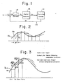
- an automatic control system employing a digital computer includes, as shown in Figure 1, an arithmetic unit 11 which calculates the difference between a manipulated variable x and a feedback variable x f fed from a controlled system, a sampler 12 which samples the difference at predetermined intervals, the digital computer 13 which receives the sampled difference and performs predetermined processing to deliver a controlled variable x , the controlled system 14 which is controlled by the controlled variable x c , and a feedback line 15.
- a sampling control method wherein data is sampled at regular time intervals, predetermined processing is executed on the basis of the sampled data, and a controlled system is controlled on the basis of the processing, said method comprising the steps of:
- a sampling control apparatus wherein, when the apparatus is in use, data is sampled at regular time intervals, predetermined processing is executed on the basis of the sampled data, and a controlled system is controlled on the basis of the processing, comprising:
- a sampling control apparatus wherein, when the apparatus is in use, data is sampled at regular time intervals, predetermined processing is executed on the basis of the sampled data, and a controlled system is controlled on the basis of the processing, comprising:
- the present invention may provide a sampling control method and apparatus capable of effecting an apparent reduction in a time delay lasting from a data sampling instant until the delivery of processed data, thereby demonstrating an effect equivalent to shortening of a sampling time interval,
- FIG. 2 is a diagram useful in describing delay time.
- a period of time ⁇ T is required for the processing executed by a digital computer, at least ⁇ T is required for the sampling time interval. That is, in a case where a difference x e which is delivered from an arithmetic unit 11 (refer to Figure 1) varies as indicated by a solid line, a control output value x , which corresponds to a sampled input value x s taken at a point marked d as a sampling input, is provided at a point marked O, in other words, at a point delayed by ⁇ T.
- This period ⁇ T is the delay time, which is dead time. This signifies that the output lags in phase over the input by the period of time d T.
- Figure 3 is diagram useful in describing a sampling control method according to the present invention.
- ⁇ x n there is calculated a difference ⁇ x n between a sampled input value x n at a certain time t n and a sampled input value x n-1 at a time t n-1 preceding by one sampling time interval.
- a value ⁇ x n /m obtained by multiplying the difference ⁇ x n by a proper coefficient 1/m is added to the input value x n , and the resulting sum is regarded as the sampled input value at the time t n . That is, according to the present invention, the following operation is executed each time data is sampled: and the result of the operation is used as the apparent sampled input value.
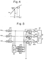
- the sampled input value at the time t n can be regarded as if it were data obtained by entering a value at a time t and delivering the value with a dead time ⁇ t relative thereto, as illustrated in Figure 4.
- the value m is properly selected by conducting an experiment for the equipment to which the present invention is to be applied, whereby the relation of t ⁇ t ⁇ t n+l can be established, giving the relation of ⁇ t ⁇ AT (sampling period). This brings forth the effect of apparently shortening the sampling period, in other words, reducing the dead time. Thus, phase lag can be diminished and system stability enhanced.
- Figure 5 is a block diagram of an embodiment in which the present invention is applied to profiling control.
- the displacement components ⁇ xn , ⁇ yn and ⁇ zn along respective axes sampled by a stylus, not shown, at a time t n are stored in corresponding registers 21X, 21Y and 21 Z .
- the displacement components ⁇ xn-1' ⁇ yn-1 and ⁇ zn-1 along the respective axes sampled at a time t n-1 have been stored in corresponding registers 22X, 22Y and 22Z.
- arithmetic units 23X, 23Y and 23Z execute the operations: and and deliver the results of these operations to adders 24X, 24Y and 24Z, respectively.
- the respective adders 24X, 25Y and 24Z execute the operations: and and apply these results ⁇ xn ', ⁇ yn ' and ⁇ zn ' to a profiling control circuit 26 as the apparent displacement values along the respective axes at the time t n .
- an updating unit 25 applies the displacement values ⁇ xn ' ⁇ yn and ⁇ zn at the time t n to the registers 22X, 22Y and 22Z, respectively.
- the profiling control circuit 26 executes well-known profiling operations so as to find feed speeds v x and v y in the respective directions of the X and Y axes and then move a cutter (not shown) and the stylus at these speeds v x and v .
- Figure 5 illustrates an arrangement based on a single-purpose hardware, the present invention is not restricted thereto but can also be constructed by employing a microcomputer.
- a time delay lasting from a data sampling instant until the delivery of processed data can be apparently reduced, whereby an effect equivalent to shortening of a sampling time can be produced. Reducing the delay time makes it possible to control a controlled system stably and accurately.
Landscapes
- Engineering & Computer Science (AREA)
- Automation & Control Theory (AREA)
- Physics & Mathematics (AREA)
- General Physics & Mathematics (AREA)
- Mechanical Engineering (AREA)
- Human Computer Interaction (AREA)
- Manufacturing & Machinery (AREA)
- Feedback Control In General (AREA)
- Control Of Position Or Direction (AREA)
Applications Claiming Priority (2)
| Application Number | Priority Date | Filing Date | Title |
|---|---|---|---|
| JP9082482A JPS58207107A (ja) | 1982-05-28 | 1982-05-28 | サンプリング制御方式 |
| JP90824/82 | 1982-05-28 |
Publications (3)
| Publication Number | Publication Date |
|---|---|
| EP0097435A2 true EP0097435A2 (de) | 1984-01-04 |
| EP0097435A3 EP0097435A3 (en) | 1985-05-22 |
| EP0097435B1 EP0097435B1 (de) | 1989-04-26 |
Family
ID=14009337
Family Applications (1)
| Application Number | Title | Priority Date | Filing Date |
|---|---|---|---|
| EP83303044A Expired EP0097435B1 (de) | 1982-05-28 | 1983-05-26 | Abtaststeuerverfahren und -einrichtung |
Country Status (3)
| Country | Link |
|---|---|
| EP (1) | EP0097435B1 (de) |
| JP (1) | JPS58207107A (de) |
| DE (1) | DE3379749D1 (de) |
Cited By (2)
| Publication number | Priority date | Publication date | Assignee | Title |
|---|---|---|---|---|
| GB2166891A (en) * | 1984-11-09 | 1986-05-14 | Ferranti Plc | Velocity control system |
| EP0262624A3 (en) * | 1986-09-29 | 1989-07-19 | Kabushiki Kaisha Sg | Positioning control system |
Families Citing this family (5)
| Publication number | Priority date | Publication date | Assignee | Title |
|---|---|---|---|---|
| JPS6069708A (ja) * | 1983-09-26 | 1985-04-20 | Matsushita Electric Ind Co Ltd | 位置制御装置 |
| JPS60108909A (ja) * | 1983-11-16 | 1985-06-14 | Omron Tateisi Electronics Co | 制御装置 |
| JPS61239303A (ja) * | 1985-04-15 | 1986-10-24 | Noritsu Co Ltd | フイ−ドフオワ−ド式制御方法 |
| JPS62143106A (ja) * | 1985-12-17 | 1987-06-26 | Nishi Nippon Plant Kogyo Kk | コンピユ−タによるプロセス制御方式 |
| JP2629486B2 (ja) * | 1991-05-29 | 1997-07-09 | 株式会社安川電機 | ネジ加工制御方法 |
Family Cites Families (5)
| Publication number | Priority date | Publication date | Assignee | Title |
|---|---|---|---|---|
| JPS4949460A (de) * | 1972-09-14 | 1974-05-14 | ||
| JPS5530752A (en) * | 1978-08-24 | 1980-03-04 | Toshiba Corp | Digital control unit |
| JPS6028624B2 (ja) * | 1980-06-18 | 1985-07-05 | ファナック株式会社 | 倣い制御装置 |
| JPS5890206A (ja) * | 1981-11-25 | 1983-05-28 | Fanuc Ltd | 位置制御方式 |
| JPS5890204A (ja) * | 1981-11-25 | 1983-05-28 | Fanuc Ltd | 位置制御装置におけるフォローアップ回路 |
-
1982
- 1982-05-28 JP JP9082482A patent/JPS58207107A/ja active Pending
-
1983
- 1983-05-26 DE DE8383303044T patent/DE3379749D1/de not_active Expired
- 1983-05-26 EP EP83303044A patent/EP0097435B1/de not_active Expired
Cited By (3)
| Publication number | Priority date | Publication date | Assignee | Title |
|---|---|---|---|---|
| GB2166891A (en) * | 1984-11-09 | 1986-05-14 | Ferranti Plc | Velocity control system |
| US4642542A (en) * | 1984-11-09 | 1987-02-10 | Ferranti Plc | Velocity control systems |
| EP0262624A3 (en) * | 1986-09-29 | 1989-07-19 | Kabushiki Kaisha Sg | Positioning control system |
Also Published As
| Publication number | Publication date |
|---|---|
| JPS58207107A (ja) | 1983-12-02 |
| DE3379749D1 (en) | 1989-06-01 |
| EP0097435B1 (de) | 1989-04-26 |
| EP0097435A3 (en) | 1985-05-22 |
Similar Documents
| Publication | Publication Date | Title |
|---|---|---|
| DE3650232T2 (de) | Rechnersteuerung mit Verzweigung in einem einzigen Zyklus. | |
| US4634946A (en) | Apparatus and method for predictive control of a dynamic system | |
| EP0553356B1 (de) | Verfahren und gerät zur vorhersage-wiederholungssteuerung für servomotor | |
| DE4414172C2 (de) | Gleit-Komma-Arithmetikeinheit und Verfahren zur Division und Quadratwurzelberechnung, die eine modifizierte Newton-Raphson Technik verwendet | |
| EP0212571A3 (de) | Verfahren und Gerät zur Durchführung von diskreten Transformen | |
| ATE175789T1 (de) | Verfahren und gerät zur ausführung mathematischer funktionen mit hilfe polynomialer annäherung und eines multiplizierers rechteckigen seitenverhältnisses | |
| US3033453A (en) | Computers | |
| EP0097435B1 (de) | Abtaststeuerverfahren und -einrichtung | |
| US4692888A (en) | Method and apparatus for generating and summing the products of pairs of numbers | |
| de Smit | A numerical solution for the multi-server queue with hyper-exponential service times | |
| EP0168787A2 (de) | Abrundungseinheit zum Gebrauch bei der arithmetischen Verarbeitung von Gleitkommadaten | |
| EP0295788A2 (de) | Einrichtung und Verfahren für eine erweiterte Arithmetik-Logik-Einheit zur Beschleunigung der ausgewählten Operationen | |
| LESTER | A system for computing the speedup of parallel programs | |
| US3280310A (en) | Aircraft landing system | |
| JPS63187366A (ja) | 移動平均演算装置 | |
| JPH03175502A (ja) | 間引き学習制御方式 | |
| EP0230721A3 (de) | Mehrprozessor-Steuerungssystem | |
| JPS58165106A (ja) | フイ−ドフオワ−ド制御装置 | |
| DEVADAS | ILL-conditioned linear systems[Ph. D. Thesis] | |
| JPS6415879A (en) | Video processing system | |
| KR0186051B1 (ko) | 가변구조 제어시스템의 채터링 제거장치 | |
| RU2012051C1 (ru) | Устройство для быстрого преобразования фурье | |
| KOVENIA et al. | Numerical algorithms for solving the Euler and Navier-Stokes equations on the basis of the splitting up method | |
| SU1067509A1 (ru) | Устройство дл вычислени полиномов | |
| SU1265697A1 (ru) | Адаптивный регул тор |
Legal Events
| Date | Code | Title | Description |
|---|---|---|---|
| PUAI | Public reference made under article 153(3) epc to a published international application that has entered the european phase |
Free format text: ORIGINAL CODE: 0009012 |
|
| AK | Designated contracting states |
Designated state(s): DE FR GB |
|
| PUAL | Search report despatched |
Free format text: ORIGINAL CODE: 0009013 |
|
| AK | Designated contracting states |
Designated state(s): DE FR GB |
|
| 17P | Request for examination filed |
Effective date: 19851015 |
|
| 17Q | First examination report despatched |
Effective date: 19870505 |
|
| GRAA | (expected) grant |
Free format text: ORIGINAL CODE: 0009210 |
|
| AK | Designated contracting states |
Kind code of ref document: B1 Designated state(s): DE FR GB |
|
| REF | Corresponds to: |
Ref document number: 3379749 Country of ref document: DE Date of ref document: 19890601 |
|
| ET | Fr: translation filed | ||
| PLBE | No opposition filed within time limit |
Free format text: ORIGINAL CODE: 0009261 |
|
| STAA | Information on the status of an ep patent application or granted ep patent |
Free format text: STATUS: NO OPPOSITION FILED WITHIN TIME LIMIT |
|
| 26N | No opposition filed | ||
| PGFP | Annual fee paid to national office [announced via postgrant information from national office to epo] |
Ref country code: FR Payment date: 19910514 Year of fee payment: 9 |
|
| PG25 | Lapsed in a contracting state [announced via postgrant information from national office to epo] |
Ref country code: FR Effective date: 19930129 |
|
| REG | Reference to a national code |
Ref country code: FR Ref legal event code: ST |
|
| PGFP | Annual fee paid to national office [announced via postgrant information from national office to epo] |
Ref country code: GB Payment date: 19930514 Year of fee payment: 11 |
|
| PGFP | Annual fee paid to national office [announced via postgrant information from national office to epo] |
Ref country code: DE Payment date: 19930602 Year of fee payment: 11 |
|
| PG25 | Lapsed in a contracting state [announced via postgrant information from national office to epo] |
Ref country code: GB Effective date: 19940526 |
|
| GBPC | Gb: european patent ceased through non-payment of renewal fee |
Effective date: 19940526 |
|
| PG25 | Lapsed in a contracting state [announced via postgrant information from national office to epo] |
Ref country code: DE Effective date: 19950201 |