EP0097414A1 - Câble plat à plusieurs conducteurs ainsi que procédé et dispositif pour sa fabrication - Google Patents
Câble plat à plusieurs conducteurs ainsi que procédé et dispositif pour sa fabrication Download PDFInfo
- Publication number
- EP0097414A1 EP0097414A1 EP83301901A EP83301901A EP0097414A1 EP 0097414 A1 EP0097414 A1 EP 0097414A1 EP 83301901 A EP83301901 A EP 83301901A EP 83301901 A EP83301901 A EP 83301901A EP 0097414 A1 EP0097414 A1 EP 0097414A1
- Authority
- EP
- European Patent Office
- Prior art keywords
- cable
- adhesive
- wires
- beads
- juxtaposed
- Prior art date
- Legal status (The legal status is an assumption and is not a legal conclusion. Google has not performed a legal analysis and makes no representation as to the accuracy of the status listed.)
- Withdrawn
Links
Images


Classifications
-
- B—PERFORMING OPERATIONS; TRANSPORTING
- B29—WORKING OF PLASTICS; WORKING OF SUBSTANCES IN A PLASTIC STATE IN GENERAL
- B29C—SHAPING OR JOINING OF PLASTICS; SHAPING OF MATERIAL IN A PLASTIC STATE, NOT OTHERWISE PROVIDED FOR; AFTER-TREATMENT OF THE SHAPED PRODUCTS, e.g. REPAIRING
- B29C66/00—General aspects of processes or apparatus for joining preformed parts
- B29C66/69—General aspects of joining filaments
-
- B—PERFORMING OPERATIONS; TRANSPORTING
- B05—SPRAYING OR ATOMISING IN GENERAL; APPLYING FLUENT MATERIALS TO SURFACES, IN GENERAL
- B05C—APPARATUS FOR APPLYING FLUENT MATERIALS TO SURFACES, IN GENERAL
- B05C5/00—Apparatus in which liquid or other fluent material is projected, poured or allowed to flow on to the surface of the work
- B05C5/02—Apparatus in which liquid or other fluent material is projected, poured or allowed to flow on to the surface of the work the liquid or other fluent material being discharged through an outlet orifice by pressure, e.g. from an outlet device in contact or almost in contact, with the work
- B05C5/0241—Apparatus in which liquid or other fluent material is projected, poured or allowed to flow on to the surface of the work the liquid or other fluent material being discharged through an outlet orifice by pressure, e.g. from an outlet device in contact or almost in contact, with the work for applying liquid or other fluent material to elongated work, e.g. wires, cables, tubes
-
- B—PERFORMING OPERATIONS; TRANSPORTING
- B29—WORKING OF PLASTICS; WORKING OF SUBSTANCES IN A PLASTIC STATE IN GENERAL
- B29C—SHAPING OR JOINING OF PLASTICS; SHAPING OF MATERIAL IN A PLASTIC STATE, NOT OTHERWISE PROVIDED FOR; AFTER-TREATMENT OF THE SHAPED PRODUCTS, e.g. REPAIRING
- B29C65/00—Joining or sealing of preformed parts, e.g. welding of plastics materials; Apparatus therefor
- B29C65/48—Joining or sealing of preformed parts, e.g. welding of plastics materials; Apparatus therefor using adhesives, i.e. using supplementary joining material; solvent bonding
- B29C65/52—Joining or sealing of preformed parts, e.g. welding of plastics materials; Apparatus therefor using adhesives, i.e. using supplementary joining material; solvent bonding characterised by the way of applying the adhesive
- B29C65/54—Joining or sealing of preformed parts, e.g. welding of plastics materials; Apparatus therefor using adhesives, i.e. using supplementary joining material; solvent bonding characterised by the way of applying the adhesive between pre-assembled parts
-
- B—PERFORMING OPERATIONS; TRANSPORTING
- B29—WORKING OF PLASTICS; WORKING OF SUBSTANCES IN A PLASTIC STATE IN GENERAL
- B29C—SHAPING OR JOINING OF PLASTICS; SHAPING OF MATERIAL IN A PLASTIC STATE, NOT OTHERWISE PROVIDED FOR; AFTER-TREATMENT OF THE SHAPED PRODUCTS, e.g. REPAIRING
- B29C66/00—General aspects of processes or apparatus for joining preformed parts
- B29C66/01—General aspects dealing with the joint area or with the area to be joined
- B29C66/05—Particular design of joint configurations
- B29C66/10—Particular design of joint configurations particular design of the joint cross-sections
- B29C66/11—Joint cross-sections comprising a single joint-segment, i.e. one of the parts to be joined comprising a single joint-segment in the joint cross-section
- B29C66/112—Single lapped joints
- B29C66/1122—Single lap to lap joints, i.e. overlap joints
-
- B—PERFORMING OPERATIONS; TRANSPORTING
- B29—WORKING OF PLASTICS; WORKING OF SUBSTANCES IN A PLASTIC STATE IN GENERAL
- B29C—SHAPING OR JOINING OF PLASTICS; SHAPING OF MATERIAL IN A PLASTIC STATE, NOT OTHERWISE PROVIDED FOR; AFTER-TREATMENT OF THE SHAPED PRODUCTS, e.g. REPAIRING
- B29C66/00—General aspects of processes or apparatus for joining preformed parts
- B29C66/01—General aspects dealing with the joint area or with the area to be joined
- B29C66/05—Particular design of joint configurations
- B29C66/20—Particular design of joint configurations particular design of the joint lines, e.g. of the weld lines
- B29C66/23—Particular design of joint configurations particular design of the joint lines, e.g. of the weld lines said joint lines being multiple and parallel or being in the form of tessellations
- B29C66/232—Particular design of joint configurations particular design of the joint lines, e.g. of the weld lines said joint lines being multiple and parallel or being in the form of tessellations said joint lines being multiple and parallel, i.e. the joint being formed by several parallel joint lines
-
- B—PERFORMING OPERATIONS; TRANSPORTING
- B29—WORKING OF PLASTICS; WORKING OF SUBSTANCES IN A PLASTIC STATE IN GENERAL
- B29C—SHAPING OR JOINING OF PLASTICS; SHAPING OF MATERIAL IN A PLASTIC STATE, NOT OTHERWISE PROVIDED FOR; AFTER-TREATMENT OF THE SHAPED PRODUCTS, e.g. REPAIRING
- B29C66/00—General aspects of processes or apparatus for joining preformed parts
- B29C66/50—General aspects of joining tubular articles; General aspects of joining long products, i.e. bars or profiled elements; General aspects of joining single elements to tubular articles, hollow articles or bars; General aspects of joining several hollow-preforms to form hollow or tubular articles
- B29C66/51—Joining tubular articles, profiled elements or bars; Joining single elements to tubular articles, hollow articles or bars; Joining several hollow-preforms to form hollow or tubular articles
- B29C66/52—Joining tubular articles, bars or profiled elements
- B29C66/526—Joining bars
-
- B—PERFORMING OPERATIONS; TRANSPORTING
- B29—WORKING OF PLASTICS; WORKING OF SUBSTANCES IN A PLASTIC STATE IN GENERAL
- B29C—SHAPING OR JOINING OF PLASTICS; SHAPING OF MATERIAL IN A PLASTIC STATE, NOT OTHERWISE PROVIDED FOR; AFTER-TREATMENT OF THE SHAPED PRODUCTS, e.g. REPAIRING
- B29C66/00—General aspects of processes or apparatus for joining preformed parts
- B29C66/80—General aspects of machine operations or constructions and parts thereof
- B29C66/83—General aspects of machine operations or constructions and parts thereof characterised by the movement of the joining or pressing tools
- B29C66/834—General aspects of machine operations or constructions and parts thereof characterised by the movement of the joining or pressing tools moving with the parts to be joined
- B29C66/8341—Roller, cylinder or drum types; Band or belt types; Ball types
- B29C66/83411—Roller, cylinder or drum types
- B29C66/83413—Roller, cylinder or drum types cooperating rollers, cylinders or drums
-
- H—ELECTRICITY
- H01—ELECTRIC ELEMENTS
- H01B—CABLES; CONDUCTORS; INSULATORS; SELECTION OF MATERIALS FOR THEIR CONDUCTIVE, INSULATING OR DIELECTRIC PROPERTIES
- H01B7/00—Insulated conductors or cables characterised by their form
- H01B7/08—Flat or ribbon cables
- H01B7/0853—Juxtaposed parallel wires, fixed to each other without a support layer
-
- B—PERFORMING OPERATIONS; TRANSPORTING
- B29—WORKING OF PLASTICS; WORKING OF SUBSTANCES IN A PLASTIC STATE IN GENERAL
- B29C—SHAPING OR JOINING OF PLASTICS; SHAPING OF MATERIAL IN A PLASTIC STATE, NOT OTHERWISE PROVIDED FOR; AFTER-TREATMENT OF THE SHAPED PRODUCTS, e.g. REPAIRING
- B29C65/00—Joining or sealing of preformed parts, e.g. welding of plastics materials; Apparatus therefor
- B29C65/48—Joining or sealing of preformed parts, e.g. welding of plastics materials; Apparatus therefor using adhesives, i.e. using supplementary joining material; solvent bonding
- B29C65/4805—Joining or sealing of preformed parts, e.g. welding of plastics materials; Apparatus therefor using adhesives, i.e. using supplementary joining material; solvent bonding characterised by the type of adhesives
- B29C65/481—Non-reactive adhesives, e.g. physically hardening adhesives
- B29C65/4815—Hot melt adhesives, e.g. thermoplastic adhesives
-
- B—PERFORMING OPERATIONS; TRANSPORTING
- B29—WORKING OF PLASTICS; WORKING OF SUBSTANCES IN A PLASTIC STATE IN GENERAL
- B29L—INDEXING SCHEME ASSOCIATED WITH SUBCLASS B29C, RELATING TO PARTICULAR ARTICLES
- B29L2031/00—Other particular articles
- B29L2031/34—Electrical apparatus, e.g. sparking plugs or parts thereof
- B29L2031/3462—Cables
Definitions
- a ribbon cable comprises a plurality of insulated wires in side-by-side parallel relationship with a securing or holding means which holds the wires in the cable as a part thereof.
- Ribbon cable as defined above, is available to the electrical industry from several manufacturers or suppliers and is used for several types of wiring and harness making operations.
- the cable is available from the suppliers with varying numbers of conductors and with conductors of varying sizes, although cable is usually supplied with all of the wires in the cable of only one size.
- the securing means which holds the wires in the cable is, in some cases, polymeric film between which the wires are laminated by rolling two sheets of film onto the wires as they are passed through laminating rolls. Ribbon cable is also produced by simply bonding the insulation of adjacent wires to each other and by the use of thread or polymeric strands which are woven into the cable.
- Ribbon cable is commonly used when it is required that a given number of conductors extend from one location to another location. For example, where adjacent racks containing electronic equipment must be provided with a harness extending between the racks, connectors can be installed on the ends of a length of ribbon cable and the connectors can then be coupled to complementary connectors in the two racks of equipment.
- a typical harness for the lighting system of an automotive vehicle may comprise a multi-conductor cable extending from a junction box towards the front end of the vehicle.
- branches of the harness will extend to the lights required at different locations on the vehicle; for example, branches may extend to the right-hand head light, to the parking lights, and to the right hazard light from the main body of the cable which would extend from the right-hand lights to the left-hand lights of the vehicle.
- Not all of the wire in the harness will necessarily be of the same size and heavier gage wires may be required for some circuits than are required for the remaining circuits.
- varying numbers of wires may be required in the harness depending upon the optional equipment to which conductors must extend and it is impractical for the harness manufacturer to maintain an inventory of ribbon cables which will satisfy all of his possible needs in manufacturing harnesses for different types of vehicles.
- ribbon cable Another disadvantage or shortcoming of ribbon cable is that it must be used in definite lengths and if some of the wires in the harness are shorter than other wires, it would be necessary in using ribbon cable to cut out the unneeded wires and discard them. In view of the fact that ribbon cable is inherently more expensive than discrete wires, this added loss could not be tolerated.
- Ribbon cable cannot, therefore, be used in manufacturing automotive harnesses, many aircraft harnesses, appliance harnesses, and harnesses for other types of equipment where the conditions are similar to those encountered in the manufacture of harnesses for motor vehicles. Notwithstanding the advantages which are obtained with the use of ribbon cable, manufacturers have continued to produce their harnesses with discrete wires and the harnesses must then be wrapped with tape or secured with bundle ties so that the cables in the harness will be retained in a reasonably compact bundle.
- the present invention is directed to the achievement of an improved form of ribbon cable which can be used in the manufacture of a wide variety of electrical harnesses which heretofor have been produced with discrete wires.
- the invention is further directed to the achievement of an apparatus and method of manufacturing harnesses.
- the invention is directed to the achievement of a flat multi-conductor cable of the type comprising a plurality of discrete insulated wires in side-by-side parallel relationship and securing means holding the wires in the cable.
- a cable in accordance with the invention is particularly characterized in that the securing means comprises a flexible adhesive which is provided on the cable between juxtaposed wires at spaced-apart locations, the wires in the cable being free of adhesive in the zones which are between the spaced-apart locations.
- the adhesive is provided on one surface of the cable in the form of beads between juxtaposed wires in the cable with each bead extending from the one surface of the cable substantially to the region of closest proximity of the juxtaposed wires.
- the adhesive is bonded to the opposed surfaces of the juxtaposed wires and each bead fills a space between the opposed surfaces.
- each bead is an extrusion of adhesive which was produced by depositing adhesive on the one surface of the cable and thereafter applying pressure to the adhesive causing it to flow to at least the region of closest proximity of the juxtaposed wires.
- the beads of adhesive are aligned between the side edges of the cable forming spaced apart rows of beads.
- the invention is also directed to the method of making flat multi-conductor cable of the type comprising a plurality of conductors in side-by-side parallel coplanar relationship, insulating material surrounding each of the conductors, and insulating material extending between juxtaposed conductors.
- the method of the present invention is particularly characterized by the steps of feeding a plurality of discrete wires, each of which has a coaxially extruded sheet of thermoplastic insulating material in surrounding relationship thereto, along converging feed paths which bring the wires into parallel side-by-side relationship thereby forming the cable.
- the cable is thereafter fed through an adhesive application zone and beads of adhesive are intermittently deposited on one surface of the cable and between juxtaposed wires.
- the invention is also directed to the achievement of an apparatus for making multi-conductor cable of the type comprising a plurality of conductors in side-by-side parallel coplanar relationship, insulating material surrounding each of the conductors and insulating material extending between juxtaposed conductors.
- Apparatus in accordance with the invention is particularly characterized in that it comprises wire feeding means for feeding a plurality of discrete insulated wires simultaneously along a wire and cable feed path which extends from a plurality of endless sources of discrete wires through an adhesive application zone thence through, and beyond, an adhesive extruding zone.
- Guide.means are provided on the path between the sources of discrete wires and the adhesive application zone, the guide means being effective to guide the discrete wires into side-by-side coplanar parallel relationship, thereby forming a multi-conductor cable.
- the adhesive application zone has an applicator therein for applying adhesive to a first surface of the cable between juxtaposed wires in the cable and the adhesive extruding zone has therein cable confining means engageable with the side edges of the cable being fed therepast and cable compressing means for compressing the cable.
- the cable confining means confines the cable to a predetermined width while the cable passes through the compressing means whereby the adhesive applied to the cable is extruded into the cable and between the opposed surfaces of juxtaposed wires.
- cable 2 in accordance with the invention comprises a plurality of insulated wires 4 in side-by-side parallel relationship with the wires secured to each other by beads 6 of an adhesive.
- the adhesive is preferably a thermoplastic hot melt adhesive, although other flexible adhesives might be used as discussed below.
- Each bead 6 has an upper flat surface 10 which forms a part of the upper surface 8 of the cable and which extends tangentially between the juxtaposed wires in the cable.
- the beads extend downwardly in Figure 2 past the regions of closest proximity 12 of the juxtaposed wires and may extend to, or substantially to, the lower surface 16 of the cable. In Figure 2, the lower surfaces of the beads 14 do not extend quite to the lower surface of the cable.
- the individual beads 6 of adhesive may have a length along the cable 2 in the range of about 3 mm to 25 mm and may be spaced apart along the length of the cable by distances ranging from about 1 cm to 6 cm or more.
- the juxtaposed wires in the cable are spaced from each other at the region of closest proximity 12 so that the beads have an hour-glass shaped cross section.
- the length of the beads and the distance between beads on the cable as noted above, are not critical and can be fixed at the time of manufacture of the cable to suit the precise service for which the cable is intended.
- the distance between juxtaposed wires should be in the range of about .01 to about .2 mm, and is not critical,. although little is gained by exceeding a spacing of about .13 cm. This matter is also discussed below with relation to the method and apparatus for manufacturing the cable.
- Figure 6 shows an alternative embodiment in which the individual wires of the cable are substantially against each other in the regions of closest proximity 12 so that the beads have a generally triangular cross section as shown at 18.
- Figure 7 shows a further embodiment in which a distinct band of adhesive 20 extends across the cable 2 and over the surface of adjacent beads.
- the band 20 of adhesive can be provided on the cable or not, as required by the intended use for the cable.
- the band 20, for example, may be useful to support the cable on the surface of a panel without permitting the insulation of the individual wires to touch the panel should it be required to avoid contact with the panel.
- Figure 4 shows an embodiment in which the cable contains six wires which have the same diameter and two wires of different diameters, the wire 28 having a larger diameter and the wire 30 having a smaller diameter than the remaining wires in the cable.
- the cable shown in Figure 4 also contains a tubular member 32 which does not have a conducting core and is not an electrical conductor.
- the tubular member 32 might be a fiber optic conductor or a pneumatic or vacuum line, as required in conjunction with the electrical harness.
- the member 32 must be of a material to which the adhesive can be bonded.
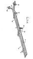
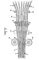
- Figure 5 shows a section of cable 2 in accordance with the invention having connectors 22, 24 installed thereon and being branched as shown at 27.
- the connector 22 has the same number of terminals therein as there are wires in the cable 2 while the connector 24 has one less terminal therein than there are wires in the cable.
- the wire at the right-hand end of the cable is, therefore, routed around the endwall of the connector 24 as shown.
- the end of the cable is branched as shown at 27 with two of the conductors extending in one direction and the remaining conductors being branched off in another direction.
- the branches each have connectors 25 installed thereon, as shown.
- the connectors 22, 24 and 25 can be installed on the cable by simply separating the wires between the rows of beads 6 and connecting the wires to the terminals in the connector with a suitable hand tool.
- an applicator of the type fully described in Application Serial Number 361,005, filed March 23, 1982 can be used to install the connectors on the cable.
- the connector applicator shown in that pending application has means for spreading the cable so that the wires will be in alignment with the terminals in the connector being installed on the cable when the assembly operation is carried out. It is advantageous to provide a gap between adjacent wires in the regions 12 to facilitate the use of the applicator.
- the connectors 22, 24, 25 have wire receiving slots which form the electrical connections between the terminals in the connectors and the wires when the wires are inserted into the slots.
- the rows of beads 6 of adhesive can be spaced apart by a distance sufficient to permit installation of the connectors on the cable between adjacent rows.
- the wires can be pulled apart and the beads broken, if necessary, to produce slack wire in the cable at the desired location of installation of the connector.
- the adhesive beads can be broken and the branch cables thereby broken out of the main cable 2.
- the beads 6 are provided as rows extending between the side edges of the cable 2 in Figure 1, alternative arrangements can be adopted if desired.
- the beads between juxtaposed pairs of wires can be spaced along the cable from adjacent beads between adjacent juxtaposed pairs of wires.
- the beads might form a sinuous path on the surface of the cable if preferred for any reason.
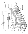
- the cable is produced by an apparatus 36 from individual reels 34 of insulated wire 4.
- the apparatus feeds the wire along a feed path which extends through a wire gathering zone 38, through an adhesive application zone 40, through an adhesive extrusion or pressing zone 42, and to the take-up reel 44.
- the take-up reel may be driven so that the wires are fed through the apparatus by the pull of the take-up reel.
- separate feed rolls for the wires may be provided at one or more locations along the feed path.
- the wire gathering zone has a pair of spaced-apart guide posts 46 which cause the wires to converge and direct them towards spaced-apart guide blades 48.
- the wires extend from the guide blades to the surface 52 of a main roller 50.
- the wires are fed under an adhesive applicator 54 and passed from the applicator between pinch rolls 56 which accurately position the wires relative to each other prior to their passing between the surface of a nip roller 58 and the surface 52 of the main roller. It will be apparent that the pinch rollers 56 cooperate with the guide blades 48 in guiding the wires into converging parallel relationship thereby forming the cable.
- the beads of adhesive When the wires pass under the adhesive applicator 54, the beads of adhesive are deposited on the upper surface of the cable but because of this viscosity of the adhesive, the adhesive does not penetrate the cable at this time.
- the wires pass between the nip roller 58 and the main roller 50 the individual beads of adhesive are rolled out as the wires are somewhat compressed and the beads are elongated.
- the beads of adhesive may be extruded through the cable and past the region of closest proximity 12 of juxtaposed wires to produce cable as shown in Figure 2. If, however, the wires are snugly against each other when the cable passes beneath the nip roller 58, cable of the type shown in Figure 6 will be produced. Cable as shown in Figure 7 will be produced if an excess of adhesive is deposited on the cable and if the rolling operation is properly controlled to prevent rolling out of the adhesive after application.
- a lubricant such as petrolatum
- the lubricant can be applied by a doctor roller 60 which rotates against the surface of the nip roller and which is continously supplied with lubricant from a dispensing source 62.
- the adhesive applicator 54 is supplied with adhesive from a reservoir 64 from which a conduit or supply line 66 extends to a pump 68.
- the pump pumps the adhesive into branch lines 70 which lead to individual orifices 76 in a nozzle 78 on the applicator 54.
- a bypass line as shown at 72 is provided, in which there is a pressure control valve 74. The pump will thus maintain a constant pressure in the supply lines 70 so that predetermined amounts of adhesive will be deposited on the cable in a given time interval.
- Individual solenoid valves 80 are provided on the supply lines 70 and are controlled, as by a controller 82, which may be in the form of a microprocessor. Adhesive will thus be dispensed through the orifices 76 only when the valves 80 are opened upon the command of the microprocessor. It is apparent then that the length of the beads and the spacing between the beads can be accurately controlled by proper programming of the microprocessor. As shown in Figure 10, for example, it may be desirable to provide relatively longer beads on the cable between the wires at the side edge of the cable and the next adjacent wires for the reason that the side edge wires may be subject to more abusive handling than the remaining wires in the cable.
- a flat conductor cable in accordance with the present invention has substantially all of the advantages and benefits which can be achieved with presently available types of flat cable and, in addition, can be used economically in the manufacture of many types of harnesses in which previously known types of cable could not be used for economic and practical reasons.
- Cable in accordance with the present invention is neat in appearance, can be routed against flat surfaces, as can known types of cable, and the individual wires in the cable can be readily identified from their positions in the cable.
- the individual beads of hot melt adhesive will hold the wires in the cable when it is handled in a normal manner during harness manufacture or installation of a harness.
- the cable can be twisted or coiled if it is necessary to pass the cable through a circular opening and after twisting, it will return to its normal flat shape.
- the hot melt adhesive is capable of undergoing substantial elongation before it will fracture and any twisting of the cable will place some of the adhesive in compression and other parts of the adhesive in tension. Portions which are compressed during manipulation of the cable will not fail or fracture even if other portions of the adhesive in the bead should be fractured or torn.
- the beads can be deliberately broken or caused to fail without damage to the wires in the cable if it is necessary to form branches as shown at 27 in Figure 5, or to install connectors as also shown in Figure 5 at 22.
- most presently available ribbon cable cannot be severed or cut to release individual wires from the cable.
- the spaced-apart beads are also advantageous in that if one bead between two juxtaposed wires should be broken, the next adjacent bead will retain the wires in the cable and in order for failure to occur in the next adjacent bead, the threshold stress required to cause failure must be overcome. In other words, since the beads are not continuous, a crack cannot be propagated along the cable.
- thermoplastic adhesives are commercially available and the choice of adhesive will depend upon many factors, such as the composition of the insulation and the desired strength in the cable and the cost of the adhesive.
- suitable thermoplastic adhesives which can be used in the manufacture of cable in accordance with the invention.
- a widely used type of insulation on wires is a filled polyvinyl chloride. Good results were obtained in the practice of the present invention with the use of wires having filled polyvinyl chloride insulation and a simple single component polyamid hot melt having a molecular weight in the range of 300 to 500.
- a hot melt polyamid adhesive of this type is available, for example, from Henkel Adhesives Company, 4620 West 77th Street, Minneapolis, Minnesota 55435.
- the particular adhesive used with the polyvinyl chloride insulated wires was Macromelt 6239 and had, upon analysis, a molecular weight as noted above. This material has a softening point in the range of 132° to 145° C and a viscosity of 58 to 85 poises at a temperature of 225° C. Adhesives of this type will undergo a substantial amount of elongation, in the range of about 200 to 900%, prior to failure within a temperature range of -18° C to +24° C.
- the adhesive satis- fies the functional requirements of the manufacturing process and the performance requirements of the beads of adhesive in the cable.
- the adhesive must have a viscosity, at the time of application to the cable, such that it will not flow freely but will remain as a globule until the cable passes under the nip roller 58.
- the adhesive must be capable of being extruded by the nip roller to produce the beads as explained above.
- the adhesive used should have a short "set up time", that is, the adhesive should develop its permanent physical characteristics shortly after it has been extruded by the nip roller.
- the hot melt thermoplastic discussed above satisfies this requirement in that it is rapidly chilled by the wires and some heat is transferred to the rolls, however, other adhesives also have short set up times.
- Cyano-acrylate adhesives could be used in the practice of the invention if the particular composition which is selected satisfies the general requirements discussed above. Quick setting elastomeric adhesives can also be used. Undoubtedly, new adhesives will become available in the future which will be suitable for purposes of the present invention.
- cable in accordance with the invention can take a variety of forms as regards the shapes and lengths of the adhesive beads. If desired, each bead can extend continuously along the length of the cable, however, there is little benefit in the provision of continuous beads rather than spaced-apart beads as shown. The spaced-apart beads will hold the wires in the cable and facilitate installation of connectors on the cable or branch, as previously discussed.
- the wires against each other, or almost against each other, as shown in Figure 6, although the profile shown in Figure 2 is preferable in that the cable shown in Figure 2 has beads which extend on each side of the region of closest proximity 12 and ordinarily will withstand more abusive handling than will a cable of the type shown in Figure 6.
- the spacing between juxtaposed wires need not be greater than about 0.13 mm, as noted above, regardless of the size of the wire. A spacing greater than this requires an excessive amount of adhesive and if the spacing is greater than about 0.13 mm, the heat imparted to the cable by the adhesive may cause damage to the insulation of the wires. A minor amount of adhesive, on the other hand, is rapidly chilled as the heat flows into the insulation of the wires and no damage will occur.
- the cohesive strength of the wire insulation should be greater than the cohesive strength of the adhesive and/or greater than the strength of the bond between the adhesive and the surface of the wire insulation. If the adhesive has a cohesive and bonding strength having these limitations, the insulation of the wire will not be damaged when one or more wires are broken out of the cable by pulling the wires from the cable and causing failure of the bead. The failure will then take place either in the adhesive or at the adhesive-surface interface, but will not take place in the insulation of the wire which will remain undamaged.
Applications Claiming Priority (2)
| Application Number | Priority Date | Filing Date | Title |
|---|---|---|---|
| US37289582A | 1982-04-29 | 1982-04-29 | |
| US372895 | 1982-04-29 |
Publications (1)
| Publication Number | Publication Date |
|---|---|
| EP0097414A1 true EP0097414A1 (fr) | 1984-01-04 |
Family
ID=23470064
Family Applications (1)
| Application Number | Title | Priority Date | Filing Date |
|---|---|---|---|
| EP83301901A Withdrawn EP0097414A1 (fr) | 1982-04-29 | 1983-04-05 | Câble plat à plusieurs conducteurs ainsi que procédé et dispositif pour sa fabrication |
Country Status (4)
| Country | Link |
|---|---|
| EP (1) | EP0097414A1 (fr) |
| JP (1) | JPS5916211A (fr) |
| BR (1) | BR8302132A (fr) |
| ES (1) | ES278139Y (fr) |
Cited By (21)
| Publication number | Priority date | Publication date | Assignee | Title |
|---|---|---|---|---|
| GB2156603A (en) * | 1984-03-26 | 1985-10-09 | Itt | Flat cable |
| US4845479A (en) * | 1986-12-22 | 1989-07-04 | Xerox Corporation | High reliability PWB interconnection for touch input systems |
| US5005611A (en) * | 1989-11-06 | 1991-04-09 | Hecker Jack D | Apparatus for modifying cables and products thereof |
| US5010642A (en) * | 1988-12-27 | 1991-04-30 | Yazaki Corporation | Method and apparatus for making a flat wiring harness |
| EP0459767A1 (fr) * | 1990-05-29 | 1991-12-04 | The Furukawa Electric Co., Ltd. | Gabarit d'alignement pour des fils séparés |
| EP0530763A1 (fr) * | 1991-09-04 | 1993-03-10 | The Furukawa Electric Co., Ltd. | Dispositif d'alignement pour des fils séparés |
| EP0613416A1 (fr) * | 1991-10-28 | 1994-09-07 | Abbott Laboratories | Ruban en plastique soude par ultra-sons et son appareil et procede de production |
| US5359150A (en) * | 1992-09-30 | 1994-10-25 | Murata Mfg. Co., Ltd. | Wire ribbon |
| US5682454A (en) * | 1994-11-21 | 1997-10-28 | Alcatel Cable | Optical-fiber cable |
| US5720908A (en) * | 1994-11-21 | 1998-02-24 | Alcatel Cable | Method of manufacturing a cylindrical optical-fiber module |
| EP0899749A2 (fr) * | 1997-08-25 | 1999-03-03 | Sumitomo Wiring Systems, Ltd. | Câble plat flexible |
| EP1440736A2 (fr) * | 2003-01-22 | 2004-07-28 | Nordson Corporation | Module, buse et procédé de distribution de matériaux liquides suivant un motif commandé |
| EP1497043A1 (fr) * | 2002-04-12 | 2005-01-19 | Nordson Corporation | Module, gicleur et procede pour la distribution commandee de modeles de substance liquide |
| DE102004061353B3 (de) * | 2004-12-21 | 2006-03-30 | Atlas Elektronik Gmbh | Verfahren und Vorrichtung zur Herstellung eines Mehrleiterkabels |
| US7086335B2 (en) * | 2003-03-07 | 2006-08-08 | Shock Tube Systems, Inc. | Redundant signal transmission system and deployment means |
| US7541545B2 (en) * | 2006-11-30 | 2009-06-02 | Schlumberger Technology Corporation | Tapeless cable assembly and methods of manufacturing same |
| US7989701B2 (en) | 2007-11-27 | 2011-08-02 | Sabic Innovative Plastics Ip B.V. | Multiconductor cable assembly and fabrication method therefor |
| US9601235B2 (en) | 2013-07-30 | 2017-03-21 | Commscope Technologies Llc | Hybrid cable with flat power conductors |
| US9682392B2 (en) | 2012-04-11 | 2017-06-20 | Nordson Corporation | Method for applying varying amounts or types of adhesive on an elastic strand |
| WO2018022031A1 (fr) * | 2016-07-27 | 2018-02-01 | Prysmian S.P.A. | Ruban de fibres optiques flexible |
| US10150252B2 (en) * | 2014-09-23 | 2018-12-11 | Stryker Sustainability Solutions, Inc. | Method of recoupling components during reprocessing |
Families Citing this family (7)
| Publication number | Priority date | Publication date | Assignee | Title |
|---|---|---|---|---|
| JPS63190211A (ja) * | 1987-01-31 | 1988-08-05 | 昭和電線電纜株式会社 | フラツトケ−ブル製造装置 |
| JPS63190212A (ja) * | 1987-01-31 | 1988-08-05 | 昭和電線電纜株式会社 | フラツトケ−ブル製造装置 |
| JPS63198116U (fr) * | 1987-06-10 | 1988-12-20 | ||
| JPS63313422A (ja) * | 1987-06-15 | 1988-12-21 | Showa Electric Wire & Cable Co Ltd | フラットケ−ブルの製造方法 |
| JP2625739B2 (ja) * | 1987-07-09 | 1997-07-02 | 東亞合成株式会社 | シート状ワイヤ・ハーネスの製造方法 |
| US4982895A (en) * | 1988-10-31 | 1991-01-08 | Nissan Motor Company, Limited | Heating system for automotive vehicles |
| JP5261343B2 (ja) * | 2009-10-09 | 2013-08-14 | 沖電線株式会社 | 可動用平型ケーブル |
Citations (7)
| Publication number | Priority date | Publication date | Assignee | Title |
|---|---|---|---|---|
| US3420208A (en) * | 1966-12-02 | 1969-01-07 | Lockwood Tech | Pneumatically controlled applicator system for adhesive and the like |
| DE7024588U (de) * | 1970-07-01 | 1971-05-06 | Diehl | Vielleiterkabel für Schwachstrom |
| GB1342716A (en) * | 1970-07-11 | 1974-01-03 | Rists Wires & Cables Ltd | Wiring harnesses |
| GB1417209A (en) * | 1972-05-25 | 1975-12-10 | Labinal | Processes and apparatuses for making flat cablings and the resulting cablings |
| US4157149A (en) * | 1977-10-31 | 1979-06-05 | Moen Lenard E | Multiple nozzle fluid dispenser for complex fluid delivery patterns |
| GB2029629A (en) * | 1978-08-15 | 1980-03-19 | Lucas Industries Ltd | Ribbon cable |
| FR2446532A1 (fr) * | 1978-12-11 | 1980-08-08 | Cables De Lyon Geoffroy Delore | Procede de fabrication de cables plats comprenant au moins deux conducteurs et dispositif de mise en oeuvre de ce procede |
-
1983
- 1983-04-05 EP EP83301901A patent/EP0097414A1/fr not_active Withdrawn
- 1983-04-19 ES ES1983278139U patent/ES278139Y/es not_active Expired
- 1983-04-26 BR BR8302132A patent/BR8302132A/pt unknown
- 1983-04-28 JP JP58076079A patent/JPS5916211A/ja active Pending
Patent Citations (7)
| Publication number | Priority date | Publication date | Assignee | Title |
|---|---|---|---|---|
| US3420208A (en) * | 1966-12-02 | 1969-01-07 | Lockwood Tech | Pneumatically controlled applicator system for adhesive and the like |
| DE7024588U (de) * | 1970-07-01 | 1971-05-06 | Diehl | Vielleiterkabel für Schwachstrom |
| GB1342716A (en) * | 1970-07-11 | 1974-01-03 | Rists Wires & Cables Ltd | Wiring harnesses |
| GB1417209A (en) * | 1972-05-25 | 1975-12-10 | Labinal | Processes and apparatuses for making flat cablings and the resulting cablings |
| US4157149A (en) * | 1977-10-31 | 1979-06-05 | Moen Lenard E | Multiple nozzle fluid dispenser for complex fluid delivery patterns |
| GB2029629A (en) * | 1978-08-15 | 1980-03-19 | Lucas Industries Ltd | Ribbon cable |
| FR2446532A1 (fr) * | 1978-12-11 | 1980-08-08 | Cables De Lyon Geoffroy Delore | Procede de fabrication de cables plats comprenant au moins deux conducteurs et dispositif de mise en oeuvre de ce procede |
Cited By (37)
| Publication number | Priority date | Publication date | Assignee | Title |
|---|---|---|---|---|
| GB2156603A (en) * | 1984-03-26 | 1985-10-09 | Itt | Flat cable |
| US4845479A (en) * | 1986-12-22 | 1989-07-04 | Xerox Corporation | High reliability PWB interconnection for touch input systems |
| US5010642A (en) * | 1988-12-27 | 1991-04-30 | Yazaki Corporation | Method and apparatus for making a flat wiring harness |
| US5005611A (en) * | 1989-11-06 | 1991-04-09 | Hecker Jack D | Apparatus for modifying cables and products thereof |
| US5207857A (en) * | 1990-05-29 | 1993-05-04 | The Furukawa Electric Co., Ltd. | Forced aligning jig for loose wires |
| EP0459767A1 (fr) * | 1990-05-29 | 1991-12-04 | The Furukawa Electric Co., Ltd. | Gabarit d'alignement pour des fils séparés |
| EP0530763A1 (fr) * | 1991-09-04 | 1993-03-10 | The Furukawa Electric Co., Ltd. | Dispositif d'alignement pour des fils séparés |
| US5318419A (en) * | 1991-09-04 | 1994-06-07 | The Furukawa Electric Co., Ltd. | Aligning jig for loose wires |
| EP0613416A1 (fr) * | 1991-10-28 | 1994-09-07 | Abbott Laboratories | Ruban en plastique soude par ultra-sons et son appareil et procede de production |
| EP0613416A4 (en) * | 1991-10-28 | 1995-12-27 | Abbott Lab | An ultrasonically welded plastic ribbon and apparatus and process for forming same. |
| US5359150A (en) * | 1992-09-30 | 1994-10-25 | Murata Mfg. Co., Ltd. | Wire ribbon |
| US5682454A (en) * | 1994-11-21 | 1997-10-28 | Alcatel Cable | Optical-fiber cable |
| US5720908A (en) * | 1994-11-21 | 1998-02-24 | Alcatel Cable | Method of manufacturing a cylindrical optical-fiber module |
| EP0899749A2 (fr) * | 1997-08-25 | 1999-03-03 | Sumitomo Wiring Systems, Ltd. | Câble plat flexible |
| EP0899749A3 (fr) * | 1997-08-25 | 2000-05-17 | Sumitomo Wiring Systems, Ltd. | Câble plat flexible |
| EP2255888A1 (fr) * | 2002-04-12 | 2010-12-01 | Nordson Corporation | Module, gicleur et procédé pour la distribution commandée d'échantillons de substance liquide |
| EP2110183A1 (fr) * | 2002-04-12 | 2009-10-21 | Nordson Corporation | Module, gicleur et procédé pour la distribution commandée d'échantillons de substance liquide |
| US9855583B2 (en) | 2002-04-12 | 2018-01-02 | Nordson Corporation | Method for dispensing controlled patterns of liquid material |
| US8800477B2 (en) | 2002-04-12 | 2014-08-12 | Nordson Corporation | Module, nozzle and method for dispensing controlled patterns of liquid material |
| EP2255887A1 (fr) * | 2002-04-12 | 2010-12-01 | Nordson Corporation | Module, gicleur et procédé pour la distribution commandée d'échantillons de substance liquide |
| EP1497043A4 (fr) * | 2002-04-12 | 2007-03-21 | Nordson Corp | Module, gicleur et procede pour la distribution commandee de modeles de substance liquide |
| EP1497043A1 (fr) * | 2002-04-12 | 2005-01-19 | Nordson Corporation | Module, gicleur et procede pour la distribution commandee de modeles de substance liquide |
| EP2253386A1 (fr) * | 2002-04-12 | 2010-11-24 | Nordson Corporation | Module, gicleur et procède pour la distribution commandée d'échantillons de substance liquide |
| US7647885B2 (en) | 2002-04-12 | 2010-01-19 | Nordson Corporation | Module, nozzle and method for dispensing controlled patterns of liquid material |
| EP1440736A3 (fr) * | 2003-01-22 | 2007-03-28 | Nordson Corporation | Module, buse et procédé de distribution de matériaux liquides suivant un motif commandé |
| US7578882B2 (en) | 2003-01-22 | 2009-08-25 | Nordson Corporation | Module, nozzle and method for dispensing controlled patterns of liquid material |
| EP1440736A2 (fr) * | 2003-01-22 | 2004-07-28 | Nordson Corporation | Module, buse et procédé de distribution de matériaux liquides suivant un motif commandé |
| US7162957B2 (en) | 2003-03-07 | 2007-01-16 | Shock Tube Systems, Inc. | Redundant signal transmission system and development method |
| US7086335B2 (en) * | 2003-03-07 | 2006-08-08 | Shock Tube Systems, Inc. | Redundant signal transmission system and deployment means |
| DE102004061353B3 (de) * | 2004-12-21 | 2006-03-30 | Atlas Elektronik Gmbh | Verfahren und Vorrichtung zur Herstellung eines Mehrleiterkabels |
| US7541545B2 (en) * | 2006-11-30 | 2009-06-02 | Schlumberger Technology Corporation | Tapeless cable assembly and methods of manufacturing same |
| US7989701B2 (en) | 2007-11-27 | 2011-08-02 | Sabic Innovative Plastics Ip B.V. | Multiconductor cable assembly and fabrication method therefor |
| US9682392B2 (en) | 2012-04-11 | 2017-06-20 | Nordson Corporation | Method for applying varying amounts or types of adhesive on an elastic strand |
| US9601235B2 (en) | 2013-07-30 | 2017-03-21 | Commscope Technologies Llc | Hybrid cable with flat power conductors |
| US10150252B2 (en) * | 2014-09-23 | 2018-12-11 | Stryker Sustainability Solutions, Inc. | Method of recoupling components during reprocessing |
| WO2018022031A1 (fr) * | 2016-07-27 | 2018-02-01 | Prysmian S.P.A. | Ruban de fibres optiques flexible |
| US10185105B2 (en) | 2016-07-27 | 2019-01-22 | Prysmian S.P.A. | Flexible optical-fiber ribbon |
Also Published As
| Publication number | Publication date |
|---|---|
| BR8302132A (pt) | 1983-12-27 |
| ES278139U (es) | 1985-02-16 |
| JPS5916211A (ja) | 1984-01-27 |
| ES278139Y (es) | 1985-09-01 |
Similar Documents
| Publication | Publication Date | Title |
|---|---|---|
| EP0097414A1 (fr) | Câble plat à plusieurs conducteurs ainsi que procédé et dispositif pour sa fabrication | |
| US6734364B2 (en) | Connecting web for cable applications | |
| US4767891A (en) | Mass terminable flat cable and cable assembly incorporating the cable | |
| US6631559B2 (en) | Process for producing a cable including a plurality of flat cables | |
| US4470195A (en) | Offset reformable jumper | |
| AU2003269974C1 (en) | Separable multi-member composite cable | |
| EP0008155B2 (fr) | Procédé et appareil pour la production de harnais de câblage | |
| US9165698B2 (en) | Cable assembly and method of making a cable assembly | |
| EP0144728A1 (fr) | Câble-ruban blindé et procédé | |
| JPS60117583A (ja) | 自動圧接機における電線長さバリエ−シヨン装置 | |
| CA1171482A (fr) | Cavalier | |
| CN115547572A (zh) | 柔性扁平线缆制造系统和制造方法、柔性扁平线缆 | |
| US4165559A (en) | Re-formable multi-conductor flat cable | |
| US5051544A (en) | Transmission cable with reduced preparation time termination section | |
| US4979292A (en) | Method of forming filament harness | |
| CN109728449B (zh) | 用于连接线缆的方法、线缆结构以及用于连接线缆的线缆连接装置 | |
| JP2002289042A (ja) | 自己接着性絶縁電線とこれを利用した多芯平行絶縁電線、およびそれらの製造装置 | |
| SK97298A3 (en) | Wiring harness wrapping | |
| EP0727790B1 (fr) | Câble électrique | |
| JPH0619928B2 (ja) | 平型多心電線およびその製造方法 | |
| JPH0515012B2 (fr) | ||
| US20020121389A1 (en) | Non-continuous connecting web for cable applications | |
| KR100517157B1 (ko) | 케이블 및 그 제조방법 | |
| JPH0654613B2 (ja) | 平型多心電線の製造方法 | |
| CA1302310C (fr) | Conduit de plastique a cable de traction integral |
Legal Events
| Date | Code | Title | Description |
|---|---|---|---|
| PUAI | Public reference made under article 153(3) epc to a published international application that has entered the european phase |
Free format text: ORIGINAL CODE: 0009012 |
|
| AK | Designated contracting states |
Designated state(s): AT BE DE FR GB IT NL SE |
|
| 17P | Request for examination filed |
Effective date: 19840622 |
|
| STAA | Information on the status of an ep patent application or granted ep patent |
Free format text: STATUS: THE APPLICATION IS DEEMED TO BE WITHDRAWN |
|
| 18D | Application deemed to be withdrawn |
Effective date: 19850926 |
|
| RIN1 | Information on inventor provided before grant (corrected) |
Inventor name: PEGRAM, WARREN JULIUS Inventor name: KEES, GERALD HENRY, JR. |