EP0096761B1 - Bildübertragendes optisches Fasersystem mit einem das Gesichtsfeld drehenden Steuermechanismus - Google Patents
Bildübertragendes optisches Fasersystem mit einem das Gesichtsfeld drehenden Steuermechanismus Download PDFInfo
- Publication number
- EP0096761B1 EP0096761B1 EP83104968A EP83104968A EP0096761B1 EP 0096761 B1 EP0096761 B1 EP 0096761B1 EP 83104968 A EP83104968 A EP 83104968A EP 83104968 A EP83104968 A EP 83104968A EP 0096761 B1 EP0096761 B1 EP 0096761B1
- Authority
- EP
- European Patent Office
- Prior art keywords
- image fiber
- mirror
- light guide
- image
- window
- Prior art date
- Legal status (The legal status is an assumption and is not a legal conclusion. Google has not performed a legal analysis and makes no representation as to the accuracy of the status listed.)
- Expired
Links
Images

Classifications
-
- G—PHYSICS
- G02—OPTICS
- G02B—OPTICAL ELEMENTS, SYSTEMS OR APPARATUS
- G02B23/00—Telescopes, e.g. binoculars; Periscopes; Instruments for viewing the inside of hollow bodies; Viewfinders; Optical aiming or sighting devices
- G02B23/24—Instruments or systems for viewing the inside of hollow bodies, e.g. fibrescopes
- G02B23/2407—Optical details
- G02B23/2423—Optical details of the distal end
-
- A—HUMAN NECESSITIES
- A61—MEDICAL OR VETERINARY SCIENCE; HYGIENE
- A61B—DIAGNOSIS; SURGERY; IDENTIFICATION
- A61B1/00—Instruments for performing medical examinations of the interior of cavities or tubes of the body by visual or photographical inspection, e.g. endoscopes; Illuminating arrangements therefor
- A61B1/00163—Optical arrangements
- A61B1/00165—Optical arrangements with light-conductive means, e.g. fibre optics
-
- A—HUMAN NECESSITIES
- A61—MEDICAL OR VETERINARY SCIENCE; HYGIENE
- A61B—DIAGNOSIS; SURGERY; IDENTIFICATION
- A61B1/00—Instruments for performing medical examinations of the interior of cavities or tubes of the body by visual or photographical inspection, e.g. endoscopes; Illuminating arrangements therefor
- A61B1/00163—Optical arrangements
- A61B1/00174—Optical arrangements characterised by the viewing angles
- A61B1/00183—Optical arrangements characterised by the viewing angles for variable viewing angles
Definitions
- the invention relates to an image fiber device of the type having a mechanism for rotating a field of view, said image fiber device comprising a main portion having an image fiber and a light guide parallel to said image fiber and an adaptor mechanism comprising a housing detachably mounted to the end of the main portion for rotating the field of view of said image fiber device, said adaptor mechanism including a window, a motor with a rotatary shaft substantially parallel to the axis of said image fiber, a mirror having a reflecting surface for reflecting an illuminating light from said light guide through said window to an object to be viewed and for receiving an image of said object through said window and reflecting said image to said image fiber, said mirror being mounted on said rotatary shaft and having its reflecting surface opposite the ends of said image fiber and light guide and opposite said window.
- Such an image fiber device is known from EP-A-0 050 922.
- the image fiber axis is not aligned with the rotational axis of the mirror which leads to a deviation of the position of the image of the object when the mirror gets turned.
- the viewing field of the mirror is covered by a transparent window which results in a reflection of the illuminating light, so that it becomes difficult to view the object.
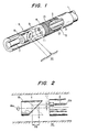
- This known device comprises a main portion 5 and a flexible tube 1 in which there is provided in parallel an image fiber 2 and a light guide 3.
- the ends of the image fiber and the light guide 3 are retained by a cap 4 and the mechanism for rotating a field of view, hereinafter referred to as an adapter 6.
- the adapter 6 is detachably mounted onto the main portion 5 and is comprised of a motor 7 provided with a rotary shaft which is substantially parallel to the axis of the image fiber 2, a 45° mirror 8 which is arranged in such a way as to be opposite to the ends of the image fiber 2 and the light guide 3 and which is mounted onto the rotary shaft of the motor 7, and a cylindrical transparent window 9 for transmitting therethrough an illuminating light reflected from the mirror 8 and for receiving therethrough an image.
- Fig. 1 also shows an object 10 which is illuminated with light from a light source (not shown) via the light guide 3.
- the image of the object 10 is reflected back to the image fiber 2 through the cylindrical transparent window 9 via the mirror 8 and an image pickup lens 11. If the mirror 8 is rotated by means of the motor 7, as indicated by the arrows in the drawing, it becomes possible to observe the entire inner surface of the pipe.
- reference numeral 12 denotes a nut for adjusting the focus
- reference numeral 13 denotes a lock nut for locking the focusing adjustment.
- the axis 2a of the image fiber 2 differs from the rotational axis 8a of the 45° mirror 8 by 6, as shown in Fig. 2, the position of the image of the object 10 (the inner surface of a pipe) which is reflected to the image fiber deviates by 26 along the longitudinal direction of the object 10 when the mirror takes positions which are different from each other by 180° (as indicated by the solid and dotted lines in Fig. 2).
- the above mentioned difference between the axis 2a of the image fiber and the rotational axis 8a of the 45° mirror results from the image fiber 2 and the light guide 3 being symmetrically arranged on both sides of the cylindrical axis of the main portion 5 in order to minimize the outer diameter of the main portion 5.
- an image fiber device is comprised of a main portion 5 which contains an image fiber 2 and a light guide 3 in parallel relation with each other.
- the image fiber device further includes a mechanism for rotating the field of view, hereinafter referred to as an adaptor 6, which is detachably mounted to the end of the main portion 5.
- an adaptor 6 which is detachably mounted to the end of the main portion 5.
- a cap 4 which has holes into which are fitted ends of the image fiber 2 and the light guide 3 so that they are retained at the end of the main portion 5.
- An image pickup lens 11 is optically connected to the image fiber 2 in the hole into which is fitted the end of the image fiber 2.
- Each of the above described holes is sealed in a watertight manner by a transparent material 14 such as a glass plate or the like.
- a plurality of screws 15 on the outer peripheral part of the cap 4 in such a manner that they are distant from one another in the circumferential direction. The plurality of screws form a portion of a one-touch mounting mechanism for the adaptor 6 which will be described later.
- the adaptor 6 is comprised of a motor 7 which has its rotary shaft aligned with the axis 2a of the image fiber 2, and a mirror 8 for reflecting an illuminating light and an image.
- reference numeral 23 denotes a lead wire to the motor 7.
- the mirror 8 is formed by evaporation coating the inner side (back surface) of a glass.
- the mirror 8 is mounted so as to form a predetermined angle (usually 45°) with respect to the rotary shaft of the motor and is connected to the rotary part of the motor via a mirror support member 16.
- the mirror is further arranged so that its reflecting side is opposite to the ends of the image fiber 2 and the light guide 3 and also opposite an aperture 9 which allows the illuminating light and the image to pass therethrough.
- the motor 7 is maintained in a housing 17.
- 0- rings 18 are used as seals between the motor 7 and the housing 17 and between the mirror support member 16 and the housing 17 so as to provide a structure which is water-resistant.
- the aperture 9 is formed as an opened window in a portion of side wall 17a of the housing 17.
- the aperture is formed so as to leave a ring 19, shown in Fig. 4, at the rear end of the side wall 17a of the housing 17 and with three window frames 20 which extend in the axial direction between the ring 19 and the housing proper, as shown in Figs. 3 and 5.
- the three window frames 20 are provided so that one of the ridgelines closely approaches the side surface of the mirror 8, as shown in Fig. 5, thereby preventing any extraneous substance from entering between the mirror 8 and the window frames 20.
- L-shaped grooves 21 of a number (usually two) which correspond to the number of screws 15 which are provided on the cap 4 of the main portion 5 (there is shown only one L-shaped groove 21 in Fig. 4). If the cap 1, at the side of the main portion 5, is inserted into the ring 19 and turned, it becomes possible to effect one-touch mounting between the main portion 5 and the adaptor 6.
- the main portion 5 and adaptor 6 can be separated from each other by a similar but reverse operation. It is desirable that a slit 22 is formed which communicates with the innermost portion of the L-shaped groove 21, in order to provide a spring function thereto.
- the image fiber of the present invention is designed to set a focusing distance (a) for a subject shown in Fig. 3, which corresponds to a focusing distance which would exist if the fiber were looking in the forward direction without a mirror, and the field of view of the image fiber is illuminated by an illuminating light from the light guide 3 within this range.
- the end surface of the light guide is obliquely ground so that the center axis (P) of the light emitted from the light fiber 3 is inclined from the light guide axis, as shown in Fig. 3.
- the center of rotation of the mirror 8 coincides with the axis 2a of the image fiber 2, the field of view is not shifted in the longitudinal direction when the mirror is rotated.
- aperture 9 is an open window, there is no reflection of the illuminating light due to the aperture thereby making it possible to more clearly view the object.
- the main portion 5 and the adaptor 6 are provided with the water-resistant mechanism, the use of the present invention in a liquid is also possible.
- Uses for the present invention include inspecting an inner surface of a pipe, inspecting the inner portion of a machine, and as a medical fiber scope or the like.
- an image fiber device with a mechanism for rotating a field of view in which there is no deviation of the field of view in the longitudinal direction and in which it is possible to clearly observe an object.
Landscapes
- Health & Medical Sciences (AREA)
- Life Sciences & Earth Sciences (AREA)
- Physics & Mathematics (AREA)
- Optics & Photonics (AREA)
- Surgery (AREA)
- Biomedical Technology (AREA)
- Animal Behavior & Ethology (AREA)
- Radiology & Medical Imaging (AREA)
- Nuclear Medicine, Radiotherapy & Molecular Imaging (AREA)
- Engineering & Computer Science (AREA)
- Biophysics (AREA)
- Heart & Thoracic Surgery (AREA)
- Medical Informatics (AREA)
- Molecular Biology (AREA)
- Pathology (AREA)
- General Health & Medical Sciences (AREA)
- Public Health (AREA)
- Veterinary Medicine (AREA)
- Astronomy & Astrophysics (AREA)
- General Physics & Mathematics (AREA)
- Instruments For Viewing The Inside Of Hollow Bodies (AREA)
- Investigating Materials By The Use Of Optical Means Adapted For Particular Applications (AREA)
- Optical Fibers, Optical Fiber Cores, And Optical Fiber Bundles (AREA)
Claims (6)
Applications Claiming Priority (2)
| Application Number | Priority Date | Filing Date | Title |
|---|---|---|---|
| JP57100349A JPS58216212A (ja) | 1982-06-11 | 1982-06-11 | 視野回転機構付イメ−ジフアイバ |
| JP100349/82 | 1982-06-11 |
Publications (2)
| Publication Number | Publication Date |
|---|---|
| EP0096761A1 EP0096761A1 (de) | 1983-12-28 |
| EP0096761B1 true EP0096761B1 (de) | 1987-03-04 |
Family
ID=14271623
Family Applications (1)
| Application Number | Title | Priority Date | Filing Date |
|---|---|---|---|
| EP83104968A Expired EP0096761B1 (de) | 1982-06-11 | 1983-05-19 | Bildübertragendes optisches Fasersystem mit einem das Gesichtsfeld drehenden Steuermechanismus |
Country Status (6)
| Country | Link |
|---|---|
| US (1) | US4640577A (de) |
| EP (1) | EP0096761B1 (de) |
| JP (1) | JPS58216212A (de) |
| AU (1) | AU553695B2 (de) |
| CA (1) | CA1243520A (de) |
| DE (1) | DE3370084D1 (de) |
Families Citing this family (14)
| Publication number | Priority date | Publication date | Assignee | Title |
|---|---|---|---|---|
| DE3425166A1 (de) * | 1984-07-09 | 1986-01-16 | Schölly Fiberoptic GmbH, 7809 Denzlingen | Endoskop |
| JPS61149118A (ja) * | 1984-12-25 | 1986-07-07 | 旭光学工業株式会社 | 硬性内視鏡 |
| JPH02191910A (ja) * | 1987-12-04 | 1990-07-27 | Olympus Optical Co Ltd | 内視鏡用先端アダプタ |
| JPH01239517A (ja) * | 1988-03-22 | 1989-09-25 | Mitsubishi Cable Ind Ltd | ファイバスコープ |
| FR2640389B1 (fr) * | 1988-12-12 | 1992-10-02 | Fibres Optiques Rech Technolo | Video-endoscopes rigides |
| US5573493A (en) * | 1993-10-08 | 1996-11-12 | United States Surgical Corporation | Endoscope attachment for changing angle of view |
| DE69922791T2 (de) * | 1998-02-19 | 2005-12-08 | California Institute Of Technology, Pasadena | Gerät zur bereitstellung eines spherischen sehfeldes während endoskopischen eingriffen |
| US6110105A (en) * | 1999-02-03 | 2000-08-29 | Durell & Gitelis, Inc. | Variable view arthroscope |
| US6638216B1 (en) | 2000-08-30 | 2003-10-28 | Durell & Gitelis, Inc. | Variable view arthroscope |
| US6929603B2 (en) * | 2000-08-30 | 2005-08-16 | Durell & Gitelis, Inc. | Variable view arthroscope |
| US7175593B2 (en) * | 2000-08-30 | 2007-02-13 | Durell & Gitelis, Inc. | Variable view arthroscope with charge coupled device |
| ATE415853T1 (de) * | 2002-02-05 | 2008-12-15 | Kersten Zaar | Endoskop mit seitblickoptik |
| WO2011132661A1 (ja) * | 2010-04-23 | 2011-10-27 | コニカミノルタオプト株式会社 | プローブ |
| CN104042178A (zh) * | 2014-07-04 | 2014-09-17 | 北京邮电大学 | 平面镜反射式360°广域视角内窥镜 |
Family Cites Families (8)
| Publication number | Priority date | Publication date | Assignee | Title |
|---|---|---|---|---|
| JPS4416936Y1 (de) * | 1965-11-22 | 1969-07-22 | ||
| FR1475008A (fr) * | 1966-02-18 | 1967-03-31 | Philips Massiot Mat Medic | Dispositif de balayage pour caméra |
| DE2155407C3 (de) * | 1970-11-06 | 1973-11-22 | Olympus Optical Co. Ltd., Tokio | Endoskop mit Bild und Lichtleiter in flexibler Rohre und mit Reflektoren zur Seitenbetrachtung |
| US3773039A (en) * | 1971-07-14 | 1973-11-20 | Olympus Optical Co | Endoscope |
| US4261638A (en) * | 1978-10-02 | 1981-04-14 | Bell Laboratories | Optical switch with rotating, reflective, concave surface |
| JPS5685324A (en) * | 1979-12-17 | 1981-07-11 | Olympus Optical Co | Optical adaptor for endoscope |
| JPS56146104A (en) * | 1980-03-26 | 1981-11-13 | Sumitomo Electric Ind Ltd | Image monitoring device |
| EP0050922B1 (de) * | 1980-10-27 | 1985-01-16 | Sumitomo Electric Industries Limited | Beobachtungssystem für die Untersuchung kleiner Öffnungen |
-
1982
- 1982-06-11 JP JP57100349A patent/JPS58216212A/ja active Pending
-
1983
- 1983-05-19 EP EP83104968A patent/EP0096761B1/de not_active Expired
- 1983-05-19 DE DE8383104968T patent/DE3370084D1/de not_active Expired
- 1983-06-03 CA CA000429696A patent/CA1243520A/en not_active Expired
- 1983-06-10 AU AU15701/83A patent/AU553695B2/en not_active Ceased
-
1985
- 1985-03-19 US US06/767,069 patent/US4640577A/en not_active Expired - Fee Related
Also Published As
| Publication number | Publication date |
|---|---|
| AU553695B2 (en) | 1986-07-24 |
| EP0096761A1 (de) | 1983-12-28 |
| US4640577A (en) | 1987-02-03 |
| DE3370084D1 (en) | 1987-04-09 |
| AU1570183A (en) | 1983-12-15 |
| JPS58216212A (ja) | 1983-12-15 |
| CA1243520A (en) | 1988-10-25 |
Similar Documents
| Publication | Publication Date | Title |
|---|---|---|
| EP0096761B1 (de) | Bildübertragendes optisches Fasersystem mit einem das Gesichtsfeld drehenden Steuermechanismus | |
| US3818902A (en) | Endoscope assembly having its optical system provided with a direction shifter | |
| US5005943A (en) | Rigid video-endoscope having a rotatable device for adjusting the orientation of an image relative to an image receiving device | |
| US4476519A (en) | Annular illumination device | |
| US4957112A (en) | Ultrasonic diagnostic apparatus | |
| EP0152181A3 (de) | Überwachungsvorrichtung | |
| US4557598A (en) | Apparatus for checking the internal surface of a pipe or the like | |
| KR950030991A (ko) | 방사선 진단장치 | |
| JPH06511081A (ja) | 可変パスレングス光透過プローブ | |
| US4406525A (en) | Light beam scanning device | |
| US4279247A (en) | Endoscope having a plurality of optical systems each provided with an identification mark element | |
| FR2783610A1 (fr) | Endoscope rotatif rigide a visee distale deviee et mise au point proximale reglable | |
| US5493400A (en) | Arrangement for projecting a test pattern onto a surface to be investigated | |
| US4021663A (en) | Automatic exposure controlling photometric device in an endoscope | |
| JPS62101165A (ja) | オプトエレクトロニクス式の走査ヘツド | |
| US5701518A (en) | Waterproof camera | |
| CA2103003A1 (en) | Image transfer system | |
| US4834516A (en) | Noninverting photo-microscope with variable power lenses | |
| US4422735A (en) | Fundus camera | |
| US6424461B1 (en) | Apparatus for observing interior from an ultramicropore space | |
| US4501476A (en) | Device for checking the light source adjustment in an incident light microscope | |
| US4613218A (en) | Illuminating light beam axis adjusting mechanism in ophthalmoscope with photographing device | |
| JP3148355B2 (ja) | 照明装置 | |
| US6028691A (en) | Machine vision | |
| US4166678A (en) | Light shield for photometer-equipped camera |
Legal Events
| Date | Code | Title | Description |
|---|---|---|---|
| PUAI | Public reference made under article 153(3) epc to a published international application that has entered the european phase |
Free format text: ORIGINAL CODE: 0009012 |
|
| AK | Designated contracting states |
Designated state(s): DE FR GB IT NL |
|
| 17P | Request for examination filed |
Effective date: 19840301 |
|
| GRAA | (expected) grant |
Free format text: ORIGINAL CODE: 0009210 |
|
| AK | Designated contracting states |
Kind code of ref document: B1 Designated state(s): DE FR GB IT NL |
|
| ET | Fr: translation filed | ||
| REF | Corresponds to: |
Ref document number: 3370084 Country of ref document: DE Date of ref document: 19870409 |
|
| ITF | It: translation for a ep patent filed | ||
| PLBE | No opposition filed within time limit |
Free format text: ORIGINAL CODE: 0009261 |
|
| STAA | Information on the status of an ep patent application or granted ep patent |
Free format text: STATUS: NO OPPOSITION FILED WITHIN TIME LIMIT |
|
| 26N | No opposition filed | ||
| ITTA | It: last paid annual fee | ||
| PGFP | Annual fee paid to national office [announced via postgrant information from national office to epo] |
Ref country code: GB Payment date: 19950510 Year of fee payment: 13 |
|
| PGFP | Annual fee paid to national office [announced via postgrant information from national office to epo] |
Ref country code: DE Payment date: 19950523 Year of fee payment: 13 |
|
| PGFP | Annual fee paid to national office [announced via postgrant information from national office to epo] |
Ref country code: FR Payment date: 19960510 Year of fee payment: 14 |
|
| PG25 | Lapsed in a contracting state [announced via postgrant information from national office to epo] |
Ref country code: GB Effective date: 19960519 |
|
| PGFP | Annual fee paid to national office [announced via postgrant information from national office to epo] |
Ref country code: NL Payment date: 19960529 Year of fee payment: 14 |
|
| GBPC | Gb: european patent ceased through non-payment of renewal fee |
Effective date: 19960519 |
|
| PG25 | Lapsed in a contracting state [announced via postgrant information from national office to epo] |
Ref country code: DE Effective date: 19970201 |
|
| PG25 | Lapsed in a contracting state [announced via postgrant information from national office to epo] |
Ref country code: NL Effective date: 19971201 |
|
| PG25 | Lapsed in a contracting state [announced via postgrant information from national office to epo] |
Ref country code: FR Free format text: LAPSE BECAUSE OF NON-PAYMENT OF DUE FEES Effective date: 19980130 |
|
| NLV4 | Nl: lapsed or anulled due to non-payment of the annual fee |
Effective date: 19971201 |
|
| REG | Reference to a national code |
Ref country code: FR Ref legal event code: ST |