EP0096643A2 - Vorrichtung zum Biegen mit gerippten Walzen mit Mitteln zur Berücksichtigung der Blechdicke und Mitteln zum Kompensieren der Durchbiegung - Google Patents
Vorrichtung zum Biegen mit gerippten Walzen mit Mitteln zur Berücksichtigung der Blechdicke und Mitteln zum Kompensieren der Durchbiegung Download PDFInfo
- Publication number
- EP0096643A2 EP0096643A2 EP83401177A EP83401177A EP0096643A2 EP 0096643 A2 EP0096643 A2 EP 0096643A2 EP 83401177 A EP83401177 A EP 83401177A EP 83401177 A EP83401177 A EP 83401177A EP 0096643 A2 EP0096643 A2 EP 0096643A2
- Authority
- EP
- European Patent Office
- Prior art keywords
- rollers
- crenellated
- movable frame
- support roller
- frame
- Prior art date
- Legal status (The legal status is an assumption and is not a legal conclusion. Google has not performed a legal analysis and makes no representation as to the accuracy of the status listed.)
- Granted
Links
- 238000005452 bending Methods 0.000 title claims abstract description 16
- 238000005096 rolling process Methods 0.000 claims abstract description 18
- 239000002184 metal Substances 0.000 claims abstract description 15
- 230000000694 effects Effects 0.000 claims abstract description 6
- 238000006243 chemical reaction Methods 0.000 claims description 8
- 125000006850 spacer group Chemical group 0.000 claims description 8
- 239000000523 sample Substances 0.000 claims description 4
- 238000001514 detection method Methods 0.000 claims description 3
- 238000003825 pressing Methods 0.000 claims description 3
- 238000006073 displacement reaction Methods 0.000 abstract description 4
- 238000004519 manufacturing process Methods 0.000 description 3
- 238000010276 construction Methods 0.000 description 1
- 230000001276 controlling effect Effects 0.000 description 1
- 238000010586 diagram Methods 0.000 description 1
- 230000001105 regulatory effect Effects 0.000 description 1
- 238000000926 separation method Methods 0.000 description 1
- XLYOFNOQVPJJNP-UHFFFAOYSA-N water Substances O XLYOFNOQVPJJNP-UHFFFAOYSA-N 0.000 description 1
- 238000003466 welding Methods 0.000 description 1
Images

Classifications
-
- B—PERFORMING OPERATIONS; TRANSPORTING
- B21—MECHANICAL METAL-WORKING WITHOUT ESSENTIALLY REMOVING MATERIAL; PUNCHING METAL
- B21D—WORKING OR PROCESSING OF SHEET METAL OR METAL TUBES, RODS OR PROFILES WITHOUT ESSENTIALLY REMOVING MATERIAL; PUNCHING METAL
- B21D5/00—Bending sheet metal along straight lines, e.g. to form simple curves
- B21D5/14—Bending sheet metal along straight lines, e.g. to form simple curves by passing between rollers
Definitions
- the present invention is in the field of mechanical work of sheets and more particularly their bending along generators by pressing between wheels; it relates more particularly to a so-called rolling machine intended to perform such work and more especially a rolling machine of the type with crenellated rollers intended for the bending of fairly thick sheets used in pressure vessels, this type of rolling machine having the advantage of bending over almost its entire length the sheet which is submitted to it.
- the known rolling machines of the aforementioned type generally consist of a support roller around which the sheet will be bent, of a pair of notched rollers of fairly small diameters, of which the slots in rolls of one are interposed with the rolls in slots on the other so as to present very close tangency points to the sheet to be bent / and a pressure roller with a diameter much larger than that of the crenellated rollers intended to press the crenelated rollers against the sheet.
- Rolling machines of the aforementioned type although they have proven to be very effective in the production at high speed of cylindrical pressure vessels such as compressed gas cylinders, hot water tanks, etc. have two drawbacks, however.
- a first drawback results from the fact that the sheets presented to the rolling machine can have different thicknesses and this due to the tolerances of the previous rolling; however, due to the approximation of the points of tangency of the rollers, a small variation in thickness has the effect of causing a significant variation in the radius of curvature; the remedy would consist in regulating, as and when the sheets are successive, the spacing between the crenellated rollers and the support roller, but such interventions are hardly compatible with production at high speed; it is therefore generally preferred to accept the sheets with a radius of curvature too large or too small and transfer the difficulty to the subsequent welding station.
- the general object of the present invention is to allow curved sheets to be obtained in the form of much more regular and uniform cylinders than the cylinders obtained with the rolling machines of the prior art, and this with the rates required by mass production.
- said means for locating the relative position of the tangency plane and of the face of the sheet are constituted by a lever-shaped feeler comprising a small arm, a large arm and a pivot axis, the end of the small arm constituting the nose of the probe and being disposed in the secant plane of crenellated rollers, the pivot being formed by the axis of a crenellated roller, and the end of the large arm comprising on the one hand pivot detection means and on the other hand, means for causing the nose to retract.
- said means for bringing the movable chassis closer to the support roller are constituted by a plurality of pairs of sloping shims, one of the wedges of a couple being integral with said movable chassis, the other wedge of the couple being integral with a general frame of the machine, the dihedral edges of each wedge being perpendicular to said plane defined by the axes of the pressure roller and the support roller, and by means for moving the movable chassis parallel to itself and parallel to the axis of the pressure roller.
- the rolling machine of the invention incorporates means for deflecting in its center in an adjustable manner the pressing roller in the direction of the crenellated rollers, the bearings of the latter being supported by the movable frame by means of slightly flexible supports.
- said means for bending consist of at least one pair of rollers, called reaction rollers, bearing on the one hand on the support roller opposite the crenellated rollers and on the other hand on the movable frame, said rollers being rotatably mounted on bearings which can be moved towards or away from one another by so-called deflection adjustment means in a direction perpendicular to the plane defined by the axes of the support roller and the pressure roller.
- reaction rollers bearing on the one hand on the support roller opposite the crenellated rollers and on the other hand on the movable frame, said rollers being rotatably mounted on bearings which can be moved towards or away from one another by so-called deflection adjustment means in a direction perpendicular to the plane defined by the axes of the support roller and the pressure roller.
- said deflection adjustment means incorporate a screw with two steps opposite each other, said screw being maneuverable from outside the frame through which it passes through a longitudinal light, each step of the screw meshing in a threaded bore of each of the bearings of said pairs of bearings.
- the mobile chassis has the shape of a U-shaped beam whose opening is directed towards the support roller;
- the general frame of the machine has a general H-shaped beam structure, one of the recesses of which is intended to accommodate said movable frame; one of the sloping wedges of each pair is secured to the spacer of said H-beam while the other sloping wedge of the couple is secured to the back of said U-beam constituting the movable frame.
- the bearings supporting the reaction rollers are guided in translation inside the chassis. movable by means of dovetail slides perpendicular to the longitudinal direction of said movable frame.
- the frame has the general shape of a gantry of which said H-beam constitutes the upper part, the spacer of this beam being horizontal, said movable frame being housed below the spacer so such that the crenellated rollers are located below the pressure roller, the support roller itself being below the crenellated rollers; it follows from this H-shaped structure of the upper part of the frame that it offers the very high rigidity necessary for the importance of the bending forces.
- the movable frame is kept suspended in the recess of the H-beam by means of a couple of spring-loaded tie rods, the foot of each of which passes through an oblong hole in the back of said movable frame.
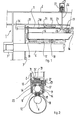
- a crenellated roller rolling machine comprises a general frame 1 composed of a horizontal upper beam 2 and legs 3 and 4 giving the frame a general form of gantry tripod; a control and command cabinet 4 ′ is arranged against the rear jamb 3.
- FIGS. 1 and 2 The specifically more functional members are illustrated more particularly by FIGS. 1 and 2, these members include a support roller 6 rotatably mounted in the bearings secured to the frame, the rear bearing 7 being secured to the rear leg 3 while the front bearing 8 is supported by the front end of the beam 2 by means of a thin web 9 having a very high tensile strength; the veil 9 allows the rolled cylinders to be removed.
- the roller 6 is driven from its end housed in the bearing 7; in the lower recess 10 of the H beam 2 is housed a movable frame 11 with a U profile; the movable chassis 11 supports and houses crenellated rollers 12 and 13 with interposed slots, a pressure roller 14 and reaction rollers 16 and 17.
- the reaction rollers 16 and 17 are supported by the movable chassis by means of bearings such as 19 and 20 which can be brought closer to each other by means of a screw 22 with two reverse steps, maneuverable from the 'exterior of the frame by a steering wheel 23; the movable frame 11 is suspended in the recess 10 of the frame 2 by means of tie rods 26 with spring 27, housed under a cover 25, the foot 28 of which passes through a slot 29 in the back 30 of the movable frame; sloping shims such as 31 secured to the back of the movable frame serve as support for sloping shims 32 secured to the spacer 33 of the H 2 beam; these sloping shims J nt a dihedral angle of 4 to 5 ° (8%).
- Means such as hydraulic jacks 34, or screw jacks, allow the longitudinal displacement of the movable chassis 11 and, by the play of the sloping wedges sliding one against the other, its displacement is increased and precise in a vertical plane; couples of wedges such as 31 and 32 are arranged at several points on the back 30 of the movable frame.
- a lever-shaped probe has a small arm 40, a large arm 41 and has its pivot formed by the axis 42 of a crenellated roller such as 12; the end 43 of the small arm 40 constitutes the probing nose; this is arranged in the secant plane 44 of the crenellated rollers 12 and 13 and exceeds the common plane 46 of tangency of the rollers 12 and 13 by about one millimeter.
- a pivot detection means such as microswitch 47; due to the position of the microswitch tipping point and the multiplication of the lever arm, position variations of the order of a hundredth of a millimeter of the nose 43 can be detected; we can therefore identify extremely precisely the position of the face 48 of the sheet relative to the plane 46.
- Maneuvering means such as jacks 49 allow the nose to be retracted when the sheet is introduced or during its bending.
- Such a probe is preferably arranged in the vicinity of the middle part of the rolling machine; it can be associated with automatic means for controlling the lowering of the mobile chassis, these automatic means can be either analog or digital.
Landscapes
- Engineering & Computer Science (AREA)
- Mechanical Engineering (AREA)
- Bending Of Plates, Rods, And Pipes (AREA)
- Press Drives And Press Lines (AREA)
- Casting Or Compression Moulding Of Plastics Or The Like (AREA)
- Shaping Of Tube Ends By Bending Or Straightening (AREA)
- Straightening Metal Sheet-Like Bodies (AREA)
Priority Applications (1)
| Application Number | Priority Date | Filing Date | Title |
|---|---|---|---|
| AT83401177T ATE51171T1 (de) | 1982-06-09 | 1983-06-09 | Vorrichtung zum biegen mit gerippten walzen mit mitteln zur beruecksichtigung der blechdicke und mitteln zum kompensieren der durchbiegung. |
Applications Claiming Priority (2)
| Application Number | Priority Date | Filing Date | Title |
|---|---|---|---|
| FR8210455A FR2528335A1 (fr) | 1982-06-09 | 1982-06-09 | Machine de cintrage a rouleaux creneles incorporant des moyens de prise en compte de l'epaisseur des toles et des moyens compensateurs de fleche |
| FR8210455 | 1982-06-09 |
Publications (3)
| Publication Number | Publication Date |
|---|---|
| EP0096643A2 true EP0096643A2 (de) | 1983-12-21 |
| EP0096643A3 EP0096643A3 (en) | 1986-07-23 |
| EP0096643B1 EP0096643B1 (de) | 1990-03-21 |
Family
ID=9275033
Family Applications (1)
| Application Number | Title | Priority Date | Filing Date |
|---|---|---|---|
| EP83401177A Expired - Lifetime EP0096643B1 (de) | 1982-06-09 | 1983-06-09 | Vorrichtung zum Biegen mit gerippten Walzen mit Mitteln zur Berücksichtigung der Blechdicke und Mitteln zum Kompensieren der Durchbiegung |
Country Status (4)
| Country | Link |
|---|---|
| EP (1) | EP0096643B1 (de) |
| AT (1) | ATE51171T1 (de) |
| DE (1) | DE3381347D1 (de) |
| FR (1) | FR2528335A1 (de) |
Cited By (1)
| Publication number | Priority date | Publication date | Assignee | Title |
|---|---|---|---|---|
| FR2637206A1 (fr) * | 1988-10-05 | 1990-04-06 | Jammes Ind Sa | Rouleuse a rouleaux creneles automatisable |
Families Citing this family (2)
| Publication number | Priority date | Publication date | Assignee | Title |
|---|---|---|---|---|
| FR2687336B1 (fr) * | 1992-02-14 | 1996-05-15 | Jammes Ind Sa | Ligne de production automatisee de viroles roulees soudees. |
| FR2750061B1 (fr) * | 1996-06-06 | 1998-09-11 | Jammes Ind Sa | Machine de cintrage de toles a rouleaux presseurs decales |
Family Cites Families (5)
| Publication number | Priority date | Publication date | Assignee | Title |
|---|---|---|---|---|
| DE1025370B (de) * | 1955-01-10 | 1958-03-06 | Froriep Gmbh Maschf | Dreiwalzenbiegemaschine mit durch verstellbare Rollenstuetzboecke abgestuetzten Unterwalzen |
| GB1083548A (en) * | 1964-12-10 | 1967-09-13 | Hingley & Sons Netherton Ltd N | Improvements relating to coil and ring-formed machines |
| US4047411A (en) * | 1977-01-03 | 1977-09-13 | The Boeing Company | Numerically controlled pyramid roll forming machine |
| US4133197A (en) * | 1977-08-29 | 1979-01-09 | Carando Machine Works | Roll-type machine for forming cylindrical sheet metal bodies |
| FR2411647A1 (fr) * | 1977-12-19 | 1979-07-13 | Jammes Sa Anc Ets | Dispositif permettant d'immobiliser en positions constantes les deux generatrices de jonction d'une virole, sur machine a cintrer les metaux en feuille |
-
1982
- 1982-06-09 FR FR8210455A patent/FR2528335A1/fr active Granted
-
1983
- 1983-06-09 DE DE8383401177T patent/DE3381347D1/de not_active Expired - Fee Related
- 1983-06-09 EP EP83401177A patent/EP0096643B1/de not_active Expired - Lifetime
- 1983-06-09 AT AT83401177T patent/ATE51171T1/de not_active IP Right Cessation
Cited By (2)
| Publication number | Priority date | Publication date | Assignee | Title |
|---|---|---|---|---|
| FR2637206A1 (fr) * | 1988-10-05 | 1990-04-06 | Jammes Ind Sa | Rouleuse a rouleaux creneles automatisable |
| EP0368686A1 (de) * | 1988-10-05 | 1990-05-16 | Jammes Industrie S.A. | Automatisierbare Rundwalzeneinrichtung mit verzahnten Walzen |
Also Published As
| Publication number | Publication date |
|---|---|
| FR2528335A1 (fr) | 1983-12-16 |
| DE3381347D1 (de) | 1990-04-26 |
| EP0096643A3 (en) | 1986-07-23 |
| EP0096643B1 (de) | 1990-03-21 |
| FR2528335B3 (de) | 1985-03-15 |
| ATE51171T1 (de) | 1990-04-15 |
Similar Documents
| Publication | Publication Date | Title |
|---|---|---|
| EP1673181B1 (de) | Verfahren zur erhöhung der steuergenauigkeit des weges eines produkts in einer richtmaschine mit ineinandergreifenden walzen und zur durchführung desselben verwendete richtanlage | |
| FR2710567A1 (fr) | Laminoir à déplacement axial. | |
| FR2718661A1 (fr) | Installation de planage d'une bande métallique. | |
| WO2011029485A1 (fr) | Machine de planage a rouleaux multiples | |
| EP0005102B1 (de) | Vorrichtung zum Messen und Steuern der Planheit von einem kaltgewalzten Metallband | |
| FR2613641A1 (fr) | Procede et installation de laminage d'un produit sous forme de bande, plus specialement une tole metallique ou un feuillard | |
| EP0707902B1 (de) | Walzanlage | |
| EP0096643B1 (de) | Vorrichtung zum Biegen mit gerippten Walzen mit Mitteln zur Berücksichtigung der Blechdicke und Mitteln zum Kompensieren der Durchbiegung | |
| EP0446130B1 (de) | Anlage zum Richten | |
| EP1005923A1 (de) | Walzwerk mit Mitteln zur Biegung der Arbeitswalzen | |
| FR2552687A1 (fr) | Machine a rouleaux de calandre pourvue d'un mecanisme de reglage des rouleaux | |
| FR2459131A1 (fr) | Dispositif de compactage a haute pression comportant un chassis de presse a tirants et organes de compression | |
| EP1804981A1 (de) | Blechbiegemaschine und produktionsanlage mit derartiger maschine | |
| FR2489296A1 (fr) | Appareil a bomber des feuilles de verre | |
| EP0767014B1 (de) | Richtmaschine mit parallelem zylinder | |
| WO1997046336A1 (fr) | Machine a cintrage de toles a rouleaux presseurs decales | |
| FR2733171A1 (fr) | Laminoir a grande ouverture | |
| CA2608462C (fr) | Dispositif de guidage de mats coulissant l'un dans l'autre, bras telescopique et procede de guidage | |
| EP0368686B1 (de) | Automatisierbare Rundwalzeneinrichtung mit verzahnten Walzen | |
| EP0730954A1 (de) | Siebdruckmaschine mit wechselbarer Rakel | |
| WO2002094465A1 (fr) | Dispositif de demontage des cylindres d'un laminoir | |
| FR2750062A1 (fr) | Machine de cintrage de toles a rouleaux presseurs decales | |
| CH209132A (fr) | Dispositif de guidage de la partie mobile d'un gazomètre. | |
| EP0006375A1 (de) | Rollenführung in einer Stranggiessanlage | |
| FR2873601A1 (fr) | Machine a redresser les fers |
Legal Events
| Date | Code | Title | Description |
|---|---|---|---|
| PUAI | Public reference made under article 153(3) epc to a published international application that has entered the european phase |
Free format text: ORIGINAL CODE: 0009012 |
|
| AK | Designated contracting states |
Designated state(s): AT BE CH DE FR GB IT LI LU NL SE |
|
| 17P | Request for examination filed |
Effective date: 19840613 |
|
| PUAL | Search report despatched |
Free format text: ORIGINAL CODE: 0009013 |
|
| AK | Designated contracting states |
Kind code of ref document: A3 Designated state(s): AT BE CH DE FR GB IT LI LU NL SE |
|
| 18D | Application deemed to be withdrawn |
Effective date: 19861231 |
|
| D18D | Application deemed to be withdrawn (deleted) | ||
| 17Q | First examination report despatched |
Effective date: 19880831 |
|
| GRAA | (expected) grant |
Free format text: ORIGINAL CODE: 0009210 |
|
| AK | Designated contracting states |
Kind code of ref document: B1 Designated state(s): AT BE CH DE FR GB IT LI LU NL SE |
|
| PG25 | Lapsed in a contracting state [announced via postgrant information from national office to epo] |
Ref country code: SE Effective date: 19900321 Ref country code: NL Effective date: 19900321 Ref country code: IT Free format text: LAPSE BECAUSE OF FAILURE TO SUBMIT A TRANSLATION OF THE DESCRIPTION OR TO PAY THE FEE WITHIN THE PRESCRIBED TIME-LIMIT;WARNING: LAPSES OF ITALIAN PATENTS WITH EFFECTIVE DATE BEFORE 2007 MAY HAVE OCCURRED AT ANY TIME BEFORE 2007. THE CORRECT EFFECTIVE DATE MAY BE DIFFERENT FROM THE ONE RECORDED. Effective date: 19900321 Ref country code: GB Effective date: 19900321 Ref country code: AT Effective date: 19900321 |
|
| REF | Corresponds to: |
Ref document number: 51171 Country of ref document: AT Date of ref document: 19900415 Kind code of ref document: T |
|
| REF | Corresponds to: |
Ref document number: 3381347 Country of ref document: DE Date of ref document: 19900426 |
|
| PG25 | Lapsed in a contracting state [announced via postgrant information from national office to epo] |
Ref country code: LU Free format text: LAPSE BECAUSE OF NON-PAYMENT OF DUE FEES Effective date: 19900630 Ref country code: LI Effective date: 19900630 Ref country code: CH Effective date: 19900630 Ref country code: BE Effective date: 19900630 |
|
| NLV1 | Nl: lapsed or annulled due to failure to fulfill the requirements of art. 29p and 29m of the patents act | ||
| GBV | Gb: ep patent (uk) treated as always having been void in accordance with gb section 77(7)/1977 [no translation filed] | ||
| BERE | Be: lapsed |
Owner name: S.A. JAMMES INDUSTRIES Effective date: 19900630 |
|
| PLBE | No opposition filed within time limit |
Free format text: ORIGINAL CODE: 0009261 |
|
| STAA | Information on the status of an ep patent application or granted ep patent |
Free format text: STATUS: NO OPPOSITION FILED WITHIN TIME LIMIT |
|
| PG25 | Lapsed in a contracting state [announced via postgrant information from national office to epo] |
Ref country code: FR Effective date: 19910228 |
|
| REG | Reference to a national code |
Ref country code: CH Ref legal event code: PL |
|
| PG25 | Lapsed in a contracting state [announced via postgrant information from national office to epo] |
Ref country code: DE Effective date: 19910301 |
|
| 26N | No opposition filed | ||
| REG | Reference to a national code |
Ref country code: FR Ref legal event code: ST |