EP0096312B1 - Kraftstoff-Einspritzdüse für Brennkraftmaschinen - Google Patents
Kraftstoff-Einspritzdüse für Brennkraftmaschinen Download PDFInfo
- Publication number
- EP0096312B1 EP0096312B1 EP83105257A EP83105257A EP0096312B1 EP 0096312 B1 EP0096312 B1 EP 0096312B1 EP 83105257 A EP83105257 A EP 83105257A EP 83105257 A EP83105257 A EP 83105257A EP 0096312 B1 EP0096312 B1 EP 0096312B1
- Authority
- EP
- European Patent Office
- Prior art keywords
- valve needle
- damping
- stroke
- fuel
- return spring
- Prior art date
- Legal status (The legal status is an assumption and is not a legal conclusion. Google has not performed a legal analysis and makes no representation as to the accuracy of the status listed.)
- Expired - Lifetime
Links
- 239000000446 fuel Substances 0.000 title claims description 17
- 238000002485 combustion reaction Methods 0.000 title claims description 16
- 238000013016 damping Methods 0.000 claims description 43
- 238000002347 injection Methods 0.000 claims description 18
- 239000007924 injection Substances 0.000 claims description 18
- 230000003111 delayed effect Effects 0.000 claims description 3
- 230000004913 activation Effects 0.000 claims description 2
- 238000010586 diagram Methods 0.000 description 6
- 238000000034 method Methods 0.000 description 6
- 238000005507 spraying Methods 0.000 description 3
- 238000006073 displacement reaction Methods 0.000 description 2
- 230000000694 effects Effects 0.000 description 2
- 230000001419 dependent effect Effects 0.000 description 1
- 238000007789 sealing Methods 0.000 description 1
- 239000007921 spray Substances 0.000 description 1
Images

Classifications
-
- F—MECHANICAL ENGINEERING; LIGHTING; HEATING; WEAPONS; BLASTING
- F02—COMBUSTION ENGINES; HOT-GAS OR COMBUSTION-PRODUCT ENGINE PLANTS
- F02M—SUPPLYING COMBUSTION ENGINES IN GENERAL WITH COMBUSTIBLE MIXTURES OR CONSTITUENTS THEREOF
- F02M61/00—Fuel-injectors not provided for in groups F02M39/00 - F02M57/00 or F02M67/00
- F02M61/04—Fuel-injectors not provided for in groups F02M39/00 - F02M57/00 or F02M67/00 having valves, e.g. having a plurality of valves in series
- F02M61/08—Fuel-injectors not provided for in groups F02M39/00 - F02M57/00 or F02M67/00 having valves, e.g. having a plurality of valves in series the valves opening in direction of fuel flow
-
- F—MECHANICAL ENGINEERING; LIGHTING; HEATING; WEAPONS; BLASTING
- F02—COMBUSTION ENGINES; HOT-GAS OR COMBUSTION-PRODUCT ENGINE PLANTS
- F02M—SUPPLYING COMBUSTION ENGINES IN GENERAL WITH COMBUSTIBLE MIXTURES OR CONSTITUENTS THEREOF
- F02M61/00—Fuel-injectors not provided for in groups F02M39/00 - F02M57/00 or F02M67/00
- F02M61/16—Details not provided for in, or of interest apart from, the apparatus of groups F02M61/02 - F02M61/14
- F02M61/20—Closing valves mechanically, e.g. arrangements of springs or weights or permanent magnets; Damping of valve lift
- F02M61/205—Means specially adapted for varying the spring tension or assisting the spring force to close the injection-valve, e.g. with damping of valve lift
Definitions
- the one controlling the opening cross section Valve needle coupled to a damping device.
- the damping device which has a damping chamber formed by a piston and a cylinder and can be acted upon by a throttle, is designed in such a way that the damping already before Is made ineffective at the end of the opening stroke of the valve needle.
- the arrangement according to the invention with the characterizing features of the main claim has the advantage that a damping of the opening movement of the valve needle and the spraying time which largely corresponds to the requirements is automatically set at each operating point of the internal combustion engine.
- damping always takes place immediately at the beginning of the opening stroke of the valve needle.
- the mutually movable parts of the damping device consisting of cylinder and piston always return to their starting position when the valve needle closes.
- the invention is based on the knowledge that the time between two injection processes becomes shorter with increasing speed and that there is a greater stroke of the valve needle with larger injection quantities.
- the time of activation of the damping means for the next opening stroke of the valve needle is delayed compared to the time of the beginning of this opening stroke, the greater the previous valve needle stroke was and ever shorter the time between successive strokes, ie the greater the speed of the internal combustion engine.
- the valve needle can therefore perform an undamped partial stroke at the beginning of an opening stroke, the length of which is automatically matched to the respective operating parameters of the internal combustion engine.
- the damping effect can be changed by shifting the start of damping from the start of injection. It is thereby achieved that the entire duration of an injection process at high speed and a large quantity can be shortened even further compared to an arrangement with initial damping of the valve needle, although a long spraying duration is maintained at low speed / quantity.
- the duration of an injection process can be made so short that when the injection system is adapted to the operating conditions, the injection duration can be changed within further limits than before.
- the arrangement could also be such that the damping remains effective over the entire opening stroke of the valve needle in the lower speed and load range or only in the critical point of idling. In some cases it could also be advisable to delay the damping means a minimum, i.e. to provide a minimum free stroke of the valve needle, which is present in all operating points of the internal combustion engine.
- the piston of the damping device is formed by the inlet-side end section of the valve needle 26 and serves as a cylinder a cap attached to this end section.
- FIG. 1 shows an injection nozzle for a diesel internal combustion engine in longitudinal section
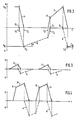
- FIGS. 2 to 4 show functional diagrams of the sequence of movements of the valve needle 26 and the cap 48 of the injection nozzle according to FIG. 1 belonging to a damping device, specifically FIG. 2 in principle, FIG. 3 at low speed - / Load range and Figure 4 in the high speed / load range of an internal combustion engine.
- the injection nozzle according to FIG. 1 has a nozzle body 10 which is clamped to a nozzle holder 14 by a union nut 12.
- a sleeve 16 Arranged between the nozzle body 10 and the nozzle holder 14 is a sleeve 16 which has an inwardly directed shoulder 18 which divides a chamber 20 from a chamber 22 of larger diameter inside the injection nozzle.
- a valve seat 24 is formed in the nozzle body 10 and a valve needle 26 is displaceably mounted, the sealing cone 27 of which is pressed against the valve seat 24 by a closing spring 28.
- the closing spring 28 is supported on the nozzle body 10 and engages via a flange part 30 on a support disk 32, which in turn is supported on a shoulder 34 det valve needle 26.
- an inlet bore 36 is formed, which opens into the chamber 20, which is connected to the chamber 22 via an opening 38 surrounded by the shoulder 18. From this, a bore 40 in the nozzle body 10 leads into an annular space 42, which is formed between the central bore wall of the nozzle body 10 and the circumference of a section 44 of the valve needle 26 with a reduced diameter and extends up to the valve seat 24. Between the flange part 30 and the nozzle body 10 there is a distance hg in the illustrated closed position, which corresponds to the total stroke of the valve needle 26. The valve needle 26 is displaced outward in the opening direction by the fuel pressure against the closing spring 28 until the flange part 30 strikes the nozzle body 10. When the valve closes, the closing spring 28 returns the valve needle 26 inward to the closed position shown.
- a piston-shaped extension 46 adjoins the shoulder 34 of the valve needle 26, which extends through the opening 38 and projects into the chamber 20.
- the diameter of the piston-shaped extension 46 corresponds to the guide diameter of the valve needle 26.
- a cap 48 is placed on the extension 46, which has a bottom 50, a jacket part 52 and a flange edge 54.
- a return spring 56 engages on the cap 48, which surrounds the jacket part 52 and presses the flange edge 54 against the collar of the sleeve 16.
- transverse slots 58 are provided, through which the fuel can always pass from the chamber 20 into the chamber 22, even when the valve needle is closed.
- a damping chamber 60 is formed in the cap 48 between the end face of the projection 46 and the base 50, which is connected to the flow path of the fuel in a throttled manner via a throttle bore 62 in the base 50.
- the projection 46 covers the transverse slots 58 in the axial direction by the path h "which is greater than the total stroke hg of the valve needle 26.
- the path h i could also be smaller by a minimal amount than the total stroke hg, so that there is still a small undamped partial stroke at the end of an opening stroke of the valve needle 26.
- the throttle bore 62 could also be partially or completely replaced by a corresponding radial play between the cap 48 and the shoulder 46.
- the piston-shaped extension 46 of the valve needle 26 and the cap 48 simultaneously form the means for damping the valve needle movement and a time-displacement element, which makes the beginning of the damping dependent on the speed and the size of the valve needle stroke.
- the damping effect and the time-displacement function are determined by appropriate coordination of the return spring 56 with the throttle bore 62 and others, the inflow and outflow of the fuel into the damping chamber 60 and parameters determining it.
- the closing stroke of the valve needle 26 is to begin, at which the cap 48 is pushed from the first end position E i to the second end position E2.
- the cap 48 travels a path ag which, as already mentioned, is somewhat smaller than the total stroke hg of the valve needle 26.
- the closing stroke is currently point t 2 ended. From then on, the cap 48 begins to move back under the influence of the return spring 56 at a predetermined speed, which is shown in the diagram as the angle a.
- a new opening stroke of valve needle 26 begins at time t 3. If, as shown in FIG. 2, cap 48 has not yet reached its first end position again at time t 3 , it moves into this end position at approximately the same speed as valve needle 26 returned. It then reaches the first end position at time t 4 . From then on, the cap 48 is held by the shoulder 18 against a further movement in the opening direction of the valve needle 26, as a result of which the damping means described become effective again. This can be seen in the diagram in that the stroke curve has a break point K at time t4. From time t 4 the valve needle 26 is transferred to the stroke end position at a damped, ie at a reduced speed, whereupon the game described is repeated.
- FIGS. 3 and 4 illustrate that the damping device according to the invention adapts itself automatically to the various operating states of the internal combustion engine.
- the internal combustion engine runs at low speed and low load, so that the cap 48 reaches its first end position before the start of the next opening stroke.
- the damping is effective over the entire opening stroke of the valve needle 26.
- Figure 4 shows an operating state in which the internal combustion engine is running at high speed under high load, in which a large valve needle stroke also occurs. In this case, the next opening stroke begins before the cap 48 has returned to its first end position.
- the break point K of the stroke curve h of the valve needle 26 has moved further towards the end of the stroke than in the operating state according to FIG. 2, so that a smaller part of the opening movement of the valve needle 26 is damped.
- FIG. 4 also makes it clear that the break point K moves towards the end of the opening of the valve needle, the faster the injection processes follow one another and the greater the valve needle stroke.
- the cap 48 is centered on the valve needle 26 and has a sufficiently large radial play with respect to the nozzle holder 14 so that the valve needle 26 can work without jamming.
- the return spring 56 extends in part over the cap 48 so that in this embodiment the means for partially damping the opening stroke of the valve needle 26 take up little space in the axial direction of the injection nozzle.
Landscapes
- Engineering & Computer Science (AREA)
- Chemical & Material Sciences (AREA)
- Combustion & Propulsion (AREA)
- Mechanical Engineering (AREA)
- General Engineering & Computer Science (AREA)
- Fuel-Injection Apparatus (AREA)
Applications Claiming Priority (2)
| Application Number | Priority Date | Filing Date | Title |
|---|---|---|---|
| DE19823221442 DE3221442A1 (de) | 1982-06-07 | 1982-06-07 | Kraftstoff-einssritzduese fuer brennkraftmaschinen |
| DE3221442 | 1982-06-07 |
Publications (2)
| Publication Number | Publication Date |
|---|---|
| EP0096312A1 EP0096312A1 (de) | 1983-12-21 |
| EP0096312B1 true EP0096312B1 (de) | 1990-12-19 |
Family
ID=6165535
Family Applications (1)
| Application Number | Title | Priority Date | Filing Date |
|---|---|---|---|
| EP83105257A Expired - Lifetime EP0096312B1 (de) | 1982-06-07 | 1983-05-27 | Kraftstoff-Einspritzdüse für Brennkraftmaschinen |
Country Status (4)
| Country | Link |
|---|---|
| US (1) | US4747545A (enExample) |
| EP (1) | EP0096312B1 (enExample) |
| JP (1) | JPS593165A (enExample) |
| DE (2) | DE3221442A1 (enExample) |
Families Citing this family (14)
| Publication number | Priority date | Publication date | Assignee | Title |
|---|---|---|---|---|
| DE3408579A1 (de) * | 1983-04-02 | 1984-10-04 | Robert Bosch Gmbh, 7000 Stuttgart | Kraftstoff-einspritzduese fuer brennkraftmaschinen |
| DE3405161A1 (de) * | 1984-02-14 | 1985-08-22 | Robert Bosch Gmbh, 7000 Stuttgart | Kraftstoff-einspritzduese fuer brennkraftmaschinen |
| JPS6128331A (ja) * | 1984-06-29 | 1986-02-08 | 株式会社北陸地所 | アワビ育成礁 |
| US5472013A (en) * | 1994-07-18 | 1995-12-05 | Outboard Marine Corporation | Fuel injection nozzle |
| US5485818A (en) * | 1995-02-22 | 1996-01-23 | Navistar International Transportation Corp. | Dimethyl ether powered engine |
| US5954487A (en) * | 1995-06-23 | 1999-09-21 | Diesel Technology Company | Fuel pump control valve assembly |
| US6113012A (en) * | 1998-06-25 | 2000-09-05 | Caterpillar Inc. | Rate shaped fuel injector with internal dual flow rate office |
| US6089470A (en) * | 1999-03-10 | 2000-07-18 | Diesel Technology Company | Control valve assembly for pumps and injectors |
| US6158419A (en) * | 1999-03-10 | 2000-12-12 | Diesel Technology Company | Control valve assembly for pumps and injectors |
| DE10006111A1 (de) * | 2000-02-11 | 2001-08-30 | Bosch Gmbh Robert | Kraftstoffeinspritzventil |
| US6450778B1 (en) | 2000-12-07 | 2002-09-17 | Diesel Technology Company | Pump system with high pressure restriction |
| EP1597500B1 (de) * | 2003-02-26 | 2009-06-17 | Bosch Rexroth AG | Direktgesteuertes druckbegrenzungsventil |
| DE102004005451A1 (de) * | 2004-02-04 | 2005-08-25 | Robert Bosch Gmbh | Kraftstoffeinspritzsystem für Brennkraftmaschinen |
| US9879645B2 (en) | 2016-02-18 | 2018-01-30 | Caterpillar Inc. | Control valve bounce limiting mechanism for fuel injectors |
Family Cites Families (11)
| Publication number | Priority date | Publication date | Assignee | Title |
|---|---|---|---|---|
| US2621015A (en) * | 1945-05-28 | 1952-12-09 | Edward Valves Inc | Valve construction |
| US2621016A (en) * | 1946-04-15 | 1952-12-09 | Edward Valves Inc | Valve construction |
| GB736794A (en) * | 1952-05-13 | 1955-09-14 | David William Edgar Kyle | Improvements in liquid fuel injection equipment for internal combustion engines |
| GB1110102A (en) * | 1963-11-26 | 1968-04-18 | Ruston & Hornsby Ltd | Improvements in fuel injection equipment for internal combustion engines |
| IT1059704B (it) * | 1975-04-19 | 1982-06-21 | Cav Ltd | Unita di ugello di iniezione di combustibile |
| DE2741634A1 (de) * | 1976-09-18 | 1978-03-23 | Lucas Industries Ltd | Kraftstoffeinspritzduese |
| JPS56500388A (enExample) * | 1979-04-13 | 1981-03-26 | ||
| JPS6029674Y2 (ja) * | 1979-09-03 | 1985-09-06 | 株式会社デンソー | 燃料噴射弁 |
| DE3105686A1 (de) * | 1981-02-17 | 1982-09-02 | Robert Bosch Gmbh, 7000 Stuttgart | "kraftstoffeinspritzduese" |
| DE3120060A1 (de) * | 1981-05-20 | 1982-12-09 | Robert Bosch Gmbh, 7000 Stuttgart | Kraftstoff-einspritzduese fuer brennkraftmaschinen |
| DE3220398A1 (de) * | 1982-01-26 | 1983-07-28 | Robert Bosch Gmbh, 7000 Stuttgart | Kraftstoff-einspritzduese fuer brennkraftmaschinen |
-
1982
- 1982-06-07 DE DE19823221442 patent/DE3221442A1/de not_active Withdrawn
- 1982-09-30 US US06/429,955 patent/US4747545A/en not_active Expired - Fee Related
-
1983
- 1983-05-27 DE DE8383105257T patent/DE3382065D1/de not_active Expired - Lifetime
- 1983-05-27 EP EP83105257A patent/EP0096312B1/de not_active Expired - Lifetime
- 1983-06-07 JP JP58100355A patent/JPS593165A/ja active Granted
Also Published As
| Publication number | Publication date |
|---|---|
| DE3221442A1 (de) | 1983-12-08 |
| US4747545A (en) | 1988-05-31 |
| DE3382065D1 (de) | 1991-01-31 |
| JPH0429873B2 (enExample) | 1992-05-20 |
| EP0096312A1 (de) | 1983-12-21 |
| JPS593165A (ja) | 1984-01-09 |
Similar Documents
| Publication | Publication Date | Title |
|---|---|---|
| EP0084662B1 (de) | Kraftstoff-Einspritzdüse für Brennkraftmaschinen | |
| DE3105686A1 (de) | "kraftstoffeinspritzduese" | |
| DE3423340A1 (de) | Kraftstoff-einspritzeinheit mit elektromagnetischem steuerventil | |
| DE2806788A1 (de) | Pumpe-duese fuer brennkraftmaschinen | |
| DE3120060A1 (de) | Kraftstoff-einspritzduese fuer brennkraftmaschinen | |
| EP0096312A1 (de) | Kraftstoff-Einspritzdüse für Brennkraftmaschinen | |
| DE2833431A1 (de) | Kraftstoffeinspritzduese | |
| DE3722265A1 (de) | Kraftstoffeinspritzpumpe | |
| DE3113475A1 (de) | "kraftstoffeinspritzduese" | |
| EP0220207B1 (de) | Kraftstoff-einspritzdüse für brennkraftmaschinen | |
| EP0135872B1 (de) | Kraftstoff-Einspritzdüse für Brennkraftmaschinen | |
| EP0153494A1 (de) | Kraftstoff-Einspritzdüse für Brennkraftmaschinen | |
| DE3125224C2 (enExample) | ||
| EP0240693B1 (de) | Kraftstoff-Einspritzdüse für Brennkraftmaschinen | |
| EP0128161B1 (de) | Kraftstoff-einspritzdüse für brennkraftmaschinen | |
| EP0137122A2 (de) | Kraftstoff-Einspritzdüse für Brennkraftmaschinen | |
| EP0081806A1 (de) | Kraftstoff-Einspritzdüse für Brennkraftmaschinen | |
| EP0386445A1 (de) | Kraftstoff-Einspritzdüse für Brennkraftmaschinen | |
| DE2648020A1 (de) | Brennstoffeinspritzvorrichtung | |
| DE3410476A1 (de) | Kraftstoff-einspritzduese fuer brennkraftmaschinen | |
| EP0126947B1 (de) | Kraftstoff-Einspritzdüse für Brennkraftmaschinen | |
| DE3518945A1 (de) | Kraftstoff-einspritzduese fuer brennkraftmaschinen | |
| DE68904496T2 (de) | Kraftstoffeinspritzventil. | |
| AT394761B (de) | Kraftstoff-einspritzduese fuer brennkraftmaschinen | |
| EP0118816B1 (de) | Kraftstoff-Einspritzdüse für Brennkraftmaschinen |
Legal Events
| Date | Code | Title | Description |
|---|---|---|---|
| PUAI | Public reference made under article 153(3) epc to a published international application that has entered the european phase |
Free format text: ORIGINAL CODE: 0009012 |
|
| 17P | Request for examination filed |
Effective date: 19830527 |
|
| AK | Designated contracting states |
Designated state(s): DE FR GB IT |
|
| GRAA | (expected) grant |
Free format text: ORIGINAL CODE: 0009210 |
|
| AK | Designated contracting states |
Kind code of ref document: B1 Designated state(s): DE FR GB IT |
|
| ET | Fr: translation filed | ||
| GBT | Gb: translation of ep patent filed (gb section 77(6)(a)/1977) | ||
| REF | Corresponds to: |
Ref document number: 3382065 Country of ref document: DE Date of ref document: 19910131 |
|
| ITF | It: translation for a ep patent filed | ||
| ITTA | It: last paid annual fee | ||
| PLBE | No opposition filed within time limit |
Free format text: ORIGINAL CODE: 0009261 |
|
| STAA | Information on the status of an ep patent application or granted ep patent |
Free format text: STATUS: NO OPPOSITION FILED WITHIN TIME LIMIT |
|
| 26N | No opposition filed | ||
| PGFP | Annual fee paid to national office [announced via postgrant information from national office to epo] |
Ref country code: GB Payment date: 19920505 Year of fee payment: 10 |
|
| PGFP | Annual fee paid to national office [announced via postgrant information from national office to epo] |
Ref country code: FR Payment date: 19920527 Year of fee payment: 10 |
|
| PGFP | Annual fee paid to national office [announced via postgrant information from national office to epo] |
Ref country code: DE Payment date: 19920728 Year of fee payment: 10 |
|
| PG25 | Lapsed in a contracting state [announced via postgrant information from national office to epo] |
Ref country code: GB Effective date: 19930527 |
|
| GBPC | Gb: european patent ceased through non-payment of renewal fee |
Effective date: 19930527 |
|
| PG25 | Lapsed in a contracting state [announced via postgrant information from national office to epo] |
Ref country code: FR Effective date: 19940131 |
|
| PG25 | Lapsed in a contracting state [announced via postgrant information from national office to epo] |
Ref country code: DE Effective date: 19940201 |
|
| REG | Reference to a national code |
Ref country code: FR Ref legal event code: ST |
|
| APAH | Appeal reference modified |
Free format text: ORIGINAL CODE: EPIDOSCREFNO |