EP0094374B1 - Méthode pour la mesure continue de la masse de particules d'aérosols dans des échantillons gazeux et dispositif pour réaliser cette méthode - Google Patents
Méthode pour la mesure continue de la masse de particules d'aérosols dans des échantillons gazeux et dispositif pour réaliser cette méthode Download PDFInfo
- Publication number
- EP0094374B1 EP0094374B1 EP83890072A EP83890072A EP0094374B1 EP 0094374 B1 EP0094374 B1 EP 0094374B1 EP 83890072 A EP83890072 A EP 83890072A EP 83890072 A EP83890072 A EP 83890072A EP 0094374 B1 EP0094374 B1 EP 0094374B1
- Authority
- EP
- European Patent Office
- Prior art keywords
- radiation
- detector
- wavelength
- mass
- absorption
- Prior art date
- Legal status (The legal status is an assumption and is not a legal conclusion. Google has not performed a legal analysis and makes no representation as to the accuracy of the status listed.)
- Expired
Links
- 239000002245 particle Substances 0.000 title claims description 41
- 239000000443 aerosol Substances 0.000 title claims description 24
- 238000005259 measurement Methods 0.000 title claims description 24
- 238000000034 method Methods 0.000 title claims description 19
- 230000005855 radiation Effects 0.000 claims description 44
- 238000010521 absorption reaction Methods 0.000 claims description 34
- 238000012360 testing method Methods 0.000 claims description 23
- 238000002485 combustion reaction Methods 0.000 claims description 12
- 230000005670 electromagnetic radiation Effects 0.000 claims description 7
- 230000010287 polarization Effects 0.000 claims description 7
- 230000003287 optical effect Effects 0.000 claims description 5
- 238000011156 evaluation Methods 0.000 claims description 4
- 239000007789 gas Substances 0.000 description 15
- 239000006096 absorbing agent Substances 0.000 description 4
- 239000012159 carrier gas Substances 0.000 description 4
- 239000000203 mixture Substances 0.000 description 4
- 230000000875 corresponding effect Effects 0.000 description 3
- 230000000052 comparative effect Effects 0.000 description 2
- 230000035945 sensitivity Effects 0.000 description 2
- OKTJSMMVPCPJKN-UHFFFAOYSA-N Carbon Chemical compound [C] OKTJSMMVPCPJKN-UHFFFAOYSA-N 0.000 description 1
- 239000004215 Carbon black (E152) Substances 0.000 description 1
- 241000663661 Lipkea Species 0.000 description 1
- 230000002745 absorbent Effects 0.000 description 1
- 239000002250 absorbent Substances 0.000 description 1
- 239000000654 additive Substances 0.000 description 1
- 230000002238 attenuated effect Effects 0.000 description 1
- 230000002596 correlated effect Effects 0.000 description 1
- 230000007423 decrease Effects 0.000 description 1
- 230000001419 dependent effect Effects 0.000 description 1
- 238000013461 design Methods 0.000 description 1
- 238000011161 development Methods 0.000 description 1
- 230000000694 effects Effects 0.000 description 1
- 238000001914 filtration Methods 0.000 description 1
- 239000000446 fuel Substances 0.000 description 1
- 229910052732 germanium Inorganic materials 0.000 description 1
- GNPVGFCGXDBREM-UHFFFAOYSA-N germanium atom Chemical compound [Ge] GNPVGFCGXDBREM-UHFFFAOYSA-N 0.000 description 1
- 229910002804 graphite Inorganic materials 0.000 description 1
- 239000010439 graphite Substances 0.000 description 1
- 230000003760 hair shine Effects 0.000 description 1
- 229930195733 hydrocarbon Natural products 0.000 description 1
- 150000002430 hydrocarbons Chemical class 0.000 description 1
- 238000000691 measurement method Methods 0.000 description 1
- 238000005293 physical law Methods 0.000 description 1
- 238000012545 processing Methods 0.000 description 1
- 238000001228 spectrum Methods 0.000 description 1
- 239000000126 substance Substances 0.000 description 1
- 230000002123 temporal effect Effects 0.000 description 1
Images
Classifications
-
- G—PHYSICS
- G01—MEASURING; TESTING
- G01N—INVESTIGATING OR ANALYSING MATERIALS BY DETERMINING THEIR CHEMICAL OR PHYSICAL PROPERTIES
- G01N21/00—Investigating or analysing materials by the use of optical means, i.e. using sub-millimetre waves, infrared, visible or ultraviolet light
- G01N21/17—Systems in which incident light is modified in accordance with the properties of the material investigated
- G01N21/25—Colour; Spectral properties, i.e. comparison of effect of material on the light at two or more different wavelengths or wavelength bands
- G01N21/31—Investigating relative effect of material at wavelengths characteristic of specific elements or molecules, e.g. atomic absorption spectrometry
- G01N21/35—Investigating relative effect of material at wavelengths characteristic of specific elements or molecules, e.g. atomic absorption spectrometry using infrared light
- G01N21/3504—Investigating relative effect of material at wavelengths characteristic of specific elements or molecules, e.g. atomic absorption spectrometry using infrared light for analysing gases, e.g. multi-gas analysis
-
- G—PHYSICS
- G01—MEASURING; TESTING
- G01N—INVESTIGATING OR ANALYSING MATERIALS BY DETERMINING THEIR CHEMICAL OR PHYSICAL PROPERTIES
- G01N21/00—Investigating or analysing materials by the use of optical means, i.e. using sub-millimetre waves, infrared, visible or ultraviolet light
- G01N21/17—Systems in which incident light is modified in accordance with the properties of the material investigated
- G01N21/47—Scattering, i.e. diffuse reflection
- G01N21/49—Scattering, i.e. diffuse reflection within a body or fluid
- G01N21/53—Scattering, i.e. diffuse reflection within a body or fluid within a flowing fluid, e.g. smoke
- G01N21/534—Scattering, i.e. diffuse reflection within a body or fluid within a flowing fluid, e.g. smoke by measuring transmission alone, i.e. determining opacity
-
- G—PHYSICS
- G01—MEASURING; TESTING
- G01N—INVESTIGATING OR ANALYSING MATERIALS BY DETERMINING THEIR CHEMICAL OR PHYSICAL PROPERTIES
- G01N15/00—Investigating characteristics of particles; Investigating permeability, pore-volume, or surface-area of porous materials
- G01N15/06—Investigating concentration of particle suspensions
-
- H—ELECTRICITY
- H02—GENERATION; CONVERSION OR DISTRIBUTION OF ELECTRIC POWER
- H02J—CIRCUIT ARRANGEMENTS OR SYSTEMS FOR SUPPLYING OR DISTRIBUTING ELECTRIC POWER; SYSTEMS FOR STORING ELECTRIC ENERGY
- H02J13/00—Circuit arrangements for providing remote indication of network conditions, e.g. an instantaneous record of the open or closed condition of each circuitbreaker in the network; Circuit arrangements for providing remote control of switching means in a power distribution network, e.g. switching in and out of current consumers by using a pulse code signal carried by the network
- H02J13/00006—Circuit arrangements for providing remote indication of network conditions, e.g. an instantaneous record of the open or closed condition of each circuitbreaker in the network; Circuit arrangements for providing remote control of switching means in a power distribution network, e.g. switching in and out of current consumers by using a pulse code signal carried by the network characterised by information or instructions transport means between the monitoring, controlling or managing units and monitored, controlled or operated power network element or electrical equipment
- H02J13/00016—Circuit arrangements for providing remote indication of network conditions, e.g. an instantaneous record of the open or closed condition of each circuitbreaker in the network; Circuit arrangements for providing remote control of switching means in a power distribution network, e.g. switching in and out of current consumers by using a pulse code signal carried by the network characterised by information or instructions transport means between the monitoring, controlling or managing units and monitored, controlled or operated power network element or electrical equipment using a wired telecommunication network or a data transmission bus
-
- Y—GENERAL TAGGING OF NEW TECHNOLOGICAL DEVELOPMENTS; GENERAL TAGGING OF CROSS-SECTIONAL TECHNOLOGIES SPANNING OVER SEVERAL SECTIONS OF THE IPC; TECHNICAL SUBJECTS COVERED BY FORMER USPC CROSS-REFERENCE ART COLLECTIONS [XRACs] AND DIGESTS
- Y02—TECHNOLOGIES OR APPLICATIONS FOR MITIGATION OR ADAPTATION AGAINST CLIMATE CHANGE
- Y02E—REDUCTION OF GREENHOUSE GAS [GHG] EMISSIONS, RELATED TO ENERGY GENERATION, TRANSMISSION OR DISTRIBUTION
- Y02E60/00—Enabling technologies; Technologies with a potential or indirect contribution to GHG emissions mitigation
-
- Y—GENERAL TAGGING OF NEW TECHNOLOGICAL DEVELOPMENTS; GENERAL TAGGING OF CROSS-SECTIONAL TECHNOLOGIES SPANNING OVER SEVERAL SECTIONS OF THE IPC; TECHNICAL SUBJECTS COVERED BY FORMER USPC CROSS-REFERENCE ART COLLECTIONS [XRACs] AND DIGESTS
- Y04—INFORMATION OR COMMUNICATION TECHNOLOGIES HAVING AN IMPACT ON OTHER TECHNOLOGY AREAS
- Y04S—SYSTEMS INTEGRATING TECHNOLOGIES RELATED TO POWER NETWORK OPERATION, COMMUNICATION OR INFORMATION TECHNOLOGIES FOR IMPROVING THE ELECTRICAL POWER GENERATION, TRANSMISSION, DISTRIBUTION, MANAGEMENT OR USAGE, i.e. SMART GRIDS
- Y04S40/00—Systems for electrical power generation, transmission, distribution or end-user application management characterised by the use of communication or information technologies, or communication or information technology specific aspects supporting them
- Y04S40/12—Systems for electrical power generation, transmission, distribution or end-user application management characterised by the use of communication or information technologies, or communication or information technology specific aspects supporting them characterised by data transport means between the monitoring, controlling or managing units and monitored, controlled or operated electrical equipment
- Y04S40/124—Systems for electrical power generation, transmission, distribution or end-user application management characterised by the use of communication or information technologies, or communication or information technology specific aspects supporting them characterised by data transport means between the monitoring, controlling or managing units and monitored, controlled or operated electrical equipment using wired telecommunication networks or data transmission busses
Definitions
- the invention relates to a method for the continuous measurement of the mass of aerosol particles in gaseous samples, in particular in the exhaust gas of internal combustion engines, a test volume containing the sample and a comparison volume with electromagnetic radiation in the optical Rayleigh range being irradiated and the difference in radiation intensities after passage through the two volumes is used as a measured value and a device according to the preamble of claim 4.
- the absorption coefficient per mass and therefore also the total absorption measured is very strongly dependent on the particle size, which is why the total mass of the aerosol particles cannot be determined without simultaneously determining at least the average particle size. Since it is known, for example in connection with the measurement of aerosol particles in the exhaust gas of internal combustion engines, that the average particle size depends on the fuel used or its additives and on the operating state of the internal combustion engine, the measurement by this known method only provides a rough estimate of the total mass actually emitted Aerosol particles. In another of the known methods, radiation of longer wavelengths, e.g. B. worked in the infrared range. At these wavelengths, the absorption coefficient per mass is independent of the particle size; the measurement takes place in the so-called optical Rayleigh range. However, since the absorption cross section of aerosol particles decreases sharply with increasing wavelength of the incident radiation, the accuracy which can be achieved with the very small measurement signal in this known method drops sharply due to external influences.
- the object of the present invention is to avoid the disadvantages of the known methods and to design a method of the type mentioned at the outset such that measurements of the particle content of gaseous samples can be carried out in a simple manner, even if this is only very small.
- electromagnetic radiation with a wavelength of 3.8 to 4.15 J.Lm is used to determine the specific mass of broadband absorbing - in particular graphitic - particles contained in the sample.
- the invention is thus based on the surprisingly found fact that in the infrared range or in the optical Rayleigh range for the aerosol particles to be measured there are frequency ranges in which none of the gases occurring in the carrier gas, in particular in the exhaust gas from internal combustion engines, contribute to provides absorption to be measured, so that the absorption of the radiation in these frequency ranges results exclusively from condensed combustion products.
- the requirements regarding the independence of the absorption which can be measured in this frequency range from the composition of the carrier gas of the gas mixture in the comparison volume are practically limited to freedom from aerosol particles that are actually to be detected, which means that there can be room air or a similarly clean gas mixture in the comparison volume and the elaborate filtering of the particle-laden sample gas before the comparison measurement is omitted.
- electromagnetic radiation of a frequency band is used to determine the specific total mass of aerosol particles contained in the sample, the center of which lies in the wavelength range from 3.35 to 3.5 ⁇ m and the half-width is at most equal to 0 , 3 ⁇ m.
- a further wavelength range for the electromagnetic radiation used can be selected, in which a clear assignment of the measured absorption to condensed combustion products in the exhaust gas sample is also possible.
- the measurement at a specific frequency can be used to determine the absorption in the entire validity range of these laws, particularly at the point of the resonance absorption of interest.
- the absorption and thus the mass loading of the gaseous sample with those particles which cause the resonance absorption can thus be inferred from the absorption measured in the wavelength range from 3.35 to 3.5 ⁇ m.
- a device for measuring the absorption of a test volume in which radiation from a radiation source passes through both a test and a comparison volume and the absorption is determined in certain wavelength ranges, in the beam path after the radiation source and in front of the measuring rooms containing the test volume or comparison volume a beam splitter is arranged, the partial beams can be combined again after passing through the respective measuring space via a deflection device, and a selection device is provided which, with a predeterminable period, only lets one of the two partial beams into a common beam path (see, for example, US Pat.
- the radiation source is designed in such a way that it emits radiation in a wavelength range from 3.35 to 3.5 J.Lm and /or 3.8 to 4.15 microns that the beam splitter as well as the deflection device has a plane-parallel disc which is transparent to the radiation used and the surface of which is inclined at a Brewster angle to the impinging beam, and that the selection device precedes it the rotating polarization analyzer arranged in the detector, which, depending on its rotational position, only allows the correspondingly polarized parts of the combined partial beams to pass, and in that the output of the detector carrying the resulting alternating signal is connected to an evaluation circuit.
- the radiation source which emits radiation in a wavelength range of 3.35 to 3.5 ⁇ m and / or 3.8 to 4.15 J.Lm
- provision must be made for the radiation path to follow the radiation source or in front of the detector is a wavelength-selective element that only transmits radiation in a wavelength range of 3.35 to 3.5 microns and 3.8 to 4.15 J.Lm.
- wavelength-selective elements By using wavelength-selective elements in the beam path, light sources with a further frequency spectrum can also be used.
- the arrangement of the plane-parallel disk at a Brewster angle against the impinging beam means that only n-polarized beam parts are reflected and the p-polarized parts pass through completely.
- Test volumes and comparison volumes can thus be irradiated with beam parts which, owing to their different polarization, can be clearly identified and can also be fed separately to the detector to determine their intensity via the rotating polarization analyzer arranged in front of the detector. An alternating signal corresponding in its period to that of the analyzer is obtained, the size of which represents a measure of the particle content sought.
- the advantage of this arrangement lies in the fact that, due to the geometric conditions of the polarization, the intensity registered by the detector is always constant over time, provided that the partial beams have the same intensity and there are no aerosol particles in the test volume.
- the polarizer can practically not be misaligned, so that fluctuations in the intensity of the incident radiation have practically no effect on the measurement.
- a rotating perforated disk could also be provided, for example, the holes of which are arranged in such a way that the two partial beams alternately fall onto the detector with a known period.
- a precise processing and a careful adjustment of the perforated disk is necessary to ensure that the full intensity of both partial beams or none of the partial beams does not hit the detector at any time. H. no light or dark peaks may occur on the detector.
- a beam splitter in the beam path after a radiation source and in front of the measuring rooms containing the test or comparison volume, a separate detector being arranged in the beam path after the test or comparison volume.
- the two detectors are connected to an evaluation circuit which preferably only records the difference between the signals of the two detectors.
- the separate detectors are connected electronically in such a way that the resulting useful signal is clearly correlated with the radiation absorption in the gaseous sample.
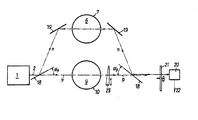
- the drawing shows the schematic representation of an apparatus for performing a method according to the invention.
- the device shown for the continuous measurement of the mass of aerosol particles in gaseous samples has a radiation source 1, the radiation emitted along the beam path 2 initially strikes a plane-parallel disk 18, which is transparent to the radiation used, and the surface of which at a Brewster angle ap the incident beam is inclined, whereby a beam splitter is created which in a simple manner supplies partial beams polarized perpendicular to one another.
- n-polarized beam ie the n-polarized part, like the p-polarized part perpendicular to it, still has full 100% intensity
- n-polarized partial beam in the direction of a mirror 19
- the p-polarized portions pass through the disk 18 in the direction of the comparison volume 9.
- the Brewster angle is defined as follows: where n o is the refractive index of the disk 18 used. The portion passing through the plane-parallel disk is not completely polarized, but still contains portions of n-polarized radiation. However, these proportions are lower the higher the refractive index n o .
- the proportion of n-polarized radiation is reduced to 1% after two passes through the disks.
- This second disk 18 is again directed at the Brewster angle ⁇ p against the partial beams, which in turn results in a reflection of the n-polarized components and a passage of the p-polarized components.
- the partial beams reunited after the second disk 18 are entered next to one another for the sake of clarity.
- a rotating polarization analyzer 21 is arranged in front of a detector 20 and, depending on its rotational position, only allows the correspondingly polarized parts of the combined partial beams to pass through, which are thus registered in time succession on the detector 20.
- At the output 22 of the detector 20 an alternating signal is obtained which corresponds in the period to that of the analyzer 21 and the size of which is equal to the difference in the intensity of the partial beams. It is sensible to set the relative intensity of the two partial beams to one another via an attenuator 23 such that signal difference 0 is determined at the detector in the case of a particle-free test volume 6.
- Known infrared sources and detectors may show fluctuations in their intensity or sensitivity, which can falsify the result during longer measurement cycles.
- One way to prevent this is, for example, to continuously calibrate the arrangement using a standardized absorber disk.
- an absorber of defined absorption is introduced into the test or comparison volume in a manner not shown here with a period which is an integer multiple R of the period of the analyzer 21. From the difference between the measured values with or without the defined absorber, the currently valid product of source intensity times detector sensitivity is obtained, with which the measured value can be calibrated without an absorber.
- the temporal resolution of the device is worse by a factor R, but the measuring accuracy is significantly increased.
- the test volume 6 can directly flow through the exhaust gas of an internal combustion engine to be tested, from which it is necessary to measure the mass of absorbing aerosol particles.
- room air or a similar pure gas mixture can be found in the comparison volume 9.
- the two partial beams passing through the measuring spaces 7, 10 are attenuated in accordance with the respective absorption properties of the gases or gaseous samples located in the test volume 6 or the comparative volume 9, the difference signal received by the detector directly matching the mass loading of the exhaust gas located in the test volume 6 with a suitable selection of the radiation parameters corresponds.
- a radiation source 1 the emitted radiation of which has a wavelength in the range from 3.8 to 4.15 J.Lm, with the aid of the arrangement shown, after a corresponding adjustment, the specific mass of broadband absorbent, in particular graphite particles contained in the sample can be directly obtained be determined.
Claims (5)
Applications Claiming Priority (2)
| Application Number | Priority Date | Filing Date | Title |
|---|---|---|---|
| AT1788/82 | 1982-05-06 | ||
| AT0178882A AT376301B (de) | 1982-05-06 | 1982-05-06 | Verfahren zur kontinuierlichen messung der masse von aeorosolteilchen in gasfoermigen proben sowie vorrichtung zur durchfuehrung des verfahrens |
Publications (2)
| Publication Number | Publication Date |
|---|---|
| EP0094374A1 EP0094374A1 (fr) | 1983-11-16 |
| EP0094374B1 true EP0094374B1 (fr) | 1986-07-30 |
Family
ID=3520989
Family Applications (1)
| Application Number | Title | Priority Date | Filing Date |
|---|---|---|---|
| EP83890072A Expired EP0094374B1 (fr) | 1982-05-06 | 1983-05-03 | Méthode pour la mesure continue de la masse de particules d'aérosols dans des échantillons gazeux et dispositif pour réaliser cette méthode |
Country Status (5)
| Country | Link |
|---|---|
| US (1) | US4525627A (fr) |
| EP (1) | EP0094374B1 (fr) |
| JP (1) | JPS58204340A (fr) |
| AT (1) | AT376301B (fr) |
| DE (1) | DE3316170A1 (fr) |
Families Citing this family (35)
| Publication number | Priority date | Publication date | Assignee | Title |
|---|---|---|---|---|
| AT379452B (de) * | 1983-04-21 | 1986-01-10 | Avl Verbrennungskraft Messtech | Verfahren zur bestimmung der massen von absorbierenden anteilen einer probe und vorrichtung zur durchfuehrung des verfahrens |
| AT383676B (de) * | 1985-04-04 | 1987-08-10 | Avl Verbrennungskraft Messtech | Verfahren zur periodischen bestimmung einer messgroesse sowie einrichtung zur durchfuehrung dieses verfahrens |
| AU573436B2 (en) * | 1985-04-11 | 1988-06-09 | Nippon Steel Corporation | Electromagnetic measurement of particle sizes |
| DE3526458A1 (de) * | 1985-07-24 | 1987-01-29 | Grundig Emv | Einrichtung zur optischen truebungsmessung von gasen |
| DE3539667A1 (de) * | 1985-11-08 | 1987-05-14 | Bruker Analytische Messtechnik | Optisches spektrometer, insbesondere infrarot-spektrometer |
| AT391208B (de) * | 1985-12-09 | 1990-09-10 | Avl Verbrennungskraft Messtech | Verfahren zur quantitativen messung von kohlenwasserstoffen |
| JPS63311146A (ja) * | 1987-06-13 | 1988-12-19 | Horiba Ltd | ガス分析計 |
| CH673534A5 (fr) * | 1987-10-19 | 1990-03-15 | Tecan Ag | |
| AT393325B (de) * | 1988-05-17 | 1991-09-25 | Avl Verbrennungskraft Messtech | Verfahren zur messung des lambda und/oder luft/kraftstoffverhaeltnisses und einrichtung zur durchfuehrung des verfahrens |
| US5381010A (en) * | 1993-12-03 | 1995-01-10 | Sleepair Corporation | Periodically alternating path and alternating wavelength bridges for quantitative and ultrasensitive measurement of vapor concentration |
| GB2300257B (en) * | 1995-04-28 | 1999-08-25 | Deutsche Forsch Luft Raumfahrt | Method and device for determination of the albedo of particles |
| DE19610439C2 (de) * | 1995-04-28 | 1998-11-26 | Deutsch Zentr Luft & Raumfahrt | Verfahren und Vorrichtung zur Bestimmung der Albedo eines beliebig geformten Partikels |
| US5977546A (en) * | 1997-05-13 | 1999-11-02 | Carlson; Lee Richard | Self normalizing radiant energy monitor and apparatus for gain independent material quantity measurements |
| GB9814701D0 (en) * | 1998-07-08 | 1998-09-02 | Avs Metrology Limited | Radiation monitoring of a physical propert of a material |
| WO2000046584A2 (fr) * | 1999-02-02 | 2000-08-10 | Rupprecht & Patashnick Company, Inc. | Dispositif de controle differentiel de masse particulaire avec systeme de correction intrinseque pour les pertes par volatilisation |
| US6205842B1 (en) | 1999-02-02 | 2001-03-27 | Rupprecht & Patashnick Company, Inc. | Differential particulate mass monitor with intrinsic correction for volatilization losses |
| US6502450B1 (en) | 1999-05-10 | 2003-01-07 | Rupprecht & Patashnik Company, Inc. | Single detector differential particulate mass monitor with intrinsic correction for volatilization losses |
| AT409039B (de) * | 1999-11-26 | 2002-05-27 | Avl List Gmbh | Verfahren zur messung der opacität in gasen |
| JP2004257909A (ja) * | 2003-02-27 | 2004-09-16 | Horiba Ltd | 粒径分布測定装置 |
| JP4014596B2 (ja) * | 2004-12-03 | 2007-11-28 | 紀本電子工業株式会社 | 浮遊粒子状物質の測定装置 |
| US7505150B2 (en) * | 2005-05-13 | 2009-03-17 | Laytec Gmbh | Device and method for the measurement of the curvature of a surface |
| GB2426579B (en) * | 2005-05-28 | 2008-01-16 | Schlumberger Holdings | Devices and methods for quantification of liquids in gas-condensate wells |
| US8436296B2 (en) * | 2009-11-06 | 2013-05-07 | Precision Energy Services, Inc. | Filter wheel assembly for downhole spectroscopy |
| US8735803B2 (en) * | 2009-11-06 | 2014-05-27 | Precision Energy Services, Inc | Multi-channel detector assembly for downhole spectroscopy |
| EP2615269B1 (fr) * | 2012-01-13 | 2014-08-13 | Schaller Automation Industrielle Automationstechnik GmbH & Co. KG | Dispositif et procédé de détermination de valeurs de mesure de gaz et/ou d'un aérosol pour une machine de travail |
| EA026528B1 (ru) * | 2014-07-01 | 2017-04-28 | Белорусский Государственный Университет (Бгу) | Способ определения массовой концентрации аэрозоля |
| US20170084426A1 (en) * | 2015-09-23 | 2017-03-23 | Lam Research Corporation | Apparatus for determining process rate |
| US9735069B2 (en) | 2015-09-23 | 2017-08-15 | Lam Research Corporation | Method and apparatus for determining process rate |
| GB201603051D0 (en) * | 2016-02-23 | 2016-04-06 | Ge Healthcare Bio Sciences Ab | A method and a measuring device for measuring the absorbance of a substance in at least one solution |
| US10784174B2 (en) | 2017-10-13 | 2020-09-22 | Lam Research Corporation | Method and apparatus for determining etch process parameters |
| RU2674560C1 (ru) * | 2017-12-28 | 2018-12-11 | Евгений Сергеевич Зубко | Способ измерения оптических характеристик атмосферы |
| CN112630108A (zh) * | 2019-09-24 | 2021-04-09 | 法雷奥汽车空调湖北有限公司 | 一种颗粒物传感器和汽车空调总成 |
| EP4053535A1 (fr) * | 2021-03-01 | 2022-09-07 | Q.ant GmbH | Capteur de particules, dispositif et procédé de détection de particules |
| DE102022123349A1 (de) | 2022-09-13 | 2024-03-14 | Q.ant GmbH | Partikelsensor und Verfahren zum Detektieren von Partikeln |
| CN116519137B (zh) * | 2023-07-04 | 2023-09-15 | 中国科学院合肥物质科学研究院 | 一种协同式偏振型天光背景辐射测量装置及方法 |
Family Cites Families (14)
| Publication number | Priority date | Publication date | Assignee | Title |
|---|---|---|---|---|
| US2500213A (en) * | 1945-03-28 | 1950-03-14 | Socony Vacuum Oil Co Inc | Geochemical exploration method by infrared analysis of soil extract solutions |
| US3390605A (en) * | 1963-10-23 | 1968-07-02 | Yanagimoto Seisakusho Co Ltd | Device for measuring simultaneously both rotatory polarization and light absorption |
| FR2097471A5 (fr) * | 1970-07-08 | 1972-03-03 | Bazelaire Eric De | |
| US3696247A (en) * | 1970-11-12 | 1972-10-03 | Lionel D Mcintosh | Vehicle exhaust emissions analyzer |
| US3790797A (en) * | 1971-09-07 | 1974-02-05 | S Sternberg | Method and system for the infrared analysis of gases |
| US3805074A (en) * | 1973-01-02 | 1974-04-16 | Texas Instruments Inc | Spectral scan air monitor |
| FI51637C (fi) * | 1974-02-22 | 1977-02-10 | Innotec Oy | Näytekanavan ja vertailukanavan suhteen symmetrinen analyysimittari. |
| CH569972A5 (fr) * | 1974-07-16 | 1975-11-28 | Cerberus Ag | |
| SE7513901L (sv) * | 1974-12-19 | 1976-06-21 | United Technologies Corp | Analyssystem for fordonsavgaser. |
| US3973848A (en) * | 1974-12-19 | 1976-08-10 | United Technologies Corporation | Automatic gas analysis and purging system |
| US4207469A (en) * | 1975-08-02 | 1980-06-10 | Sir Howard Grubb Parsons and Company Ltd. | Analysis of emulsions and suspensions |
| DE2721909A1 (de) * | 1977-05-14 | 1978-11-23 | Philips Patentverwaltung | Verfahren und anordnung zur selbsttaetigen periodischen kompensation von empfindlichkeitsunterschieden bei zweistrahl-photometern |
| DK151393C (da) * | 1978-12-06 | 1988-05-16 | Foss Electric As N | Fremgangsmaade til kvantitativ bestemmelse af fedt i en vandig fedtemulsion |
| US4229653A (en) * | 1979-03-30 | 1980-10-21 | Sri International | Method and apparatus for monitoring particulate mass concentration of emissions from stationary sources |
-
1982
- 1982-05-06 AT AT0178882A patent/AT376301B/de not_active IP Right Cessation
-
1983
- 1983-05-03 EP EP83890072A patent/EP0094374B1/fr not_active Expired
- 1983-05-04 US US06/491,553 patent/US4525627A/en not_active Expired - Lifetime
- 1983-05-04 DE DE3316170A patent/DE3316170A1/de active Granted
- 1983-05-06 JP JP58079993A patent/JPS58204340A/ja active Granted
Non-Patent Citations (1)
| Title |
|---|
| Aerosol Science and Technology 1: 225-234, (1982) * |
Also Published As
| Publication number | Publication date |
|---|---|
| AT376301B (de) | 1984-11-12 |
| JPS58204340A (ja) | 1983-11-29 |
| JPH0231820B2 (fr) | 1990-07-17 |
| DE3316170A1 (de) | 1983-11-17 |
| EP0094374A1 (fr) | 1983-11-16 |
| US4525627A (en) | 1985-06-25 |
| DE3316170C2 (fr) | 1987-04-30 |
| ATA178882A (de) | 1984-03-15 |
Similar Documents
| Publication | Publication Date | Title |
|---|---|---|
| EP0094374B1 (fr) | Méthode pour la mesure continue de la masse de particules d'aérosols dans des échantillons gazeux et dispositif pour réaliser cette méthode | |
| EP0034156B1 (fr) | Procede et dispositif pour la determination de glucose dans serum ou l'urine | |
| EP0226569B1 (fr) | Procédé pour la mesure quantitative d'hydrocarbures | |
| DE10240204B3 (de) | Verfahren zur optischen Messung von schwarzem Kohlenstoff in der Atmosphäre und Einrichtung zur Durchführung des Verfahrens | |
| WO2006002740A1 (fr) | Analyseur de gaz a infrarouge non dispersif | |
| EP1183523B1 (fr) | Appareil d'analyse | |
| DE3240559C2 (de) | Verfahren zur kontinuierlichen Messung der Masse von Aerosolteilchen in gasförmigen Proben sowie Vorrichtung zur Durchführung des Verfahrens | |
| DE10392663T5 (de) | Foto-akustisches Erfassungsverfahren zum Messen der Konzentration von Nicht-Kolenwasserstoff-Komponenten einer methanhaltigen Gasmischung | |
| DE102009046279A1 (de) | Messgerät zur Abgasmessung | |
| DE19509822C2 (de) | Ölkonzentrations-Meßgerät | |
| DE3030002A1 (de) | Nichtdispersiver infrarot-gasanalysator | |
| DE3938142C2 (fr) | ||
| DE3116344C2 (fr) | ||
| WO1999009391A2 (fr) | Photometre a spectroscopie d'absorption non dispersive dans l'infrarouge (ndir) pour la mesure de plusieurs constituants | |
| DE2744168C3 (de) | Magnetooptisches Spektralphotometer | |
| AT515495B1 (de) | Verfahren und Vorrichtung zur Bestimmung einer Partikelkonzentration eines mit Partikel geladenen Messgases | |
| EP0123672A2 (fr) | Procédé pour la détermination des masses de parties absorbantes dans un échantillon et installation pour la mise en oeuvre de ce procédé | |
| DE19819192C1 (de) | Gasanalysator | |
| DE19741123C2 (de) | Verfahren zur quantitativen Bestimmung von Ruß in einer Rußprobe und Vorrichtung zur Durchführung des Verfahrens | |
| DE19735599A1 (de) | Verfahren und Vorrichtung zur gleichzeitigen Messung von Konzentrationen verschiedener Gaskomponenten insbesondere zur Messung von Isotopenverhältnissen in Gasen | |
| DE102009058394B3 (de) | Verfahren zur Messung der Konzentration mindestens einer Gaskomponente in einem Messgas | |
| DE4025789A1 (de) | Optisches verfahren zur bestimmung des partikelgehaltes in gasen und fluessigkeiten | |
| DE102010050549A1 (de) | Verfahren und Vorrichtung zum Erfassen von Wasser in einem Flugkraftstoff | |
| DE4337227C2 (de) | Zwei Verfahren für die Detektion von absorbierenden Substanzen in Lösungen sowie eine Vorrichtung für die Messung von linearen und Sättigungssignalen | |
| DE4130586A1 (de) | Verfahren zur bestimmung der teilchengroesse-fraktionen in schwebestaeuben |
Legal Events
| Date | Code | Title | Description |
|---|---|---|---|
| PUAI | Public reference made under article 153(3) epc to a published international application that has entered the european phase |
Free format text: ORIGINAL CODE: 0009012 |
|
| AK | Designated contracting states |
Designated state(s): FR GB IT SE |
|
| ITCL | It: translation for ep claims filed |
Representative=s name: MODIANO & ASSOCIATI S.R.L. |
|
| 17P | Request for examination filed |
Effective date: 19831201 |
|
| EL | Fr: translation of claims filed | ||
| GRAA | (expected) grant |
Free format text: ORIGINAL CODE: 0009210 |
|
| AK | Designated contracting states |
Kind code of ref document: B1 Designated state(s): FR GB IT SE |
|
| ITF | It: translation for a ep patent filed |
Owner name: MODIANO & ASSOCIATI S.R.L. |
|
| ET | Fr: translation filed | ||
| PLBE | No opposition filed within time limit |
Free format text: ORIGINAL CODE: 0009261 |
|
| STAA | Information on the status of an ep patent application or granted ep patent |
Free format text: STATUS: NO OPPOSITION FILED WITHIN TIME LIMIT |
|
| 26N | No opposition filed | ||
| ITTA | It: last paid annual fee | ||
| PGFP | Annual fee paid to national office [announced via postgrant information from national office to epo] |
Ref country code: GB Payment date: 19940428 Year of fee payment: 12 |
|
| PGFP | Annual fee paid to national office [announced via postgrant information from national office to epo] |
Ref country code: SE Payment date: 19940530 Year of fee payment: 12 Ref country code: FR Payment date: 19940530 Year of fee payment: 12 |
|
| EAL | Se: european patent in force in sweden |
Ref document number: 83890072.8 |
|
| PG25 | Lapsed in a contracting state [announced via postgrant information from national office to epo] |
Ref country code: GB Effective date: 19950503 |
|
| PG25 | Lapsed in a contracting state [announced via postgrant information from national office to epo] |
Ref country code: SE Effective date: 19950504 |
|
| GBPC | Gb: european patent ceased through non-payment of renewal fee |
Effective date: 19950503 |
|
| EUG | Se: european patent has lapsed |
Ref document number: 83890072.8 |
|
| PG25 | Lapsed in a contracting state [announced via postgrant information from national office to epo] |
Ref country code: FR Effective date: 19960229 |
|
| REG | Reference to a national code |
Ref country code: FR Ref legal event code: ST |
|
| REG | Reference to a national code |
Ref country code: FR Ref legal event code: ST |