EP0093896B1 - Perkussionsinstrument - Google Patents
Perkussionsinstrument Download PDFInfo
- Publication number
- EP0093896B1 EP0093896B1 EP83103681A EP83103681A EP0093896B1 EP 0093896 B1 EP0093896 B1 EP 0093896B1 EP 83103681 A EP83103681 A EP 83103681A EP 83103681 A EP83103681 A EP 83103681A EP 0093896 B1 EP0093896 B1 EP 0093896B1
- Authority
- EP
- European Patent Office
- Prior art keywords
- rocking lever
- drive
- testing head
- percussion apparatus
- percussion
- Prior art date
- Legal status (The legal status is an assumption and is not a legal conclusion. Google has not performed a legal analysis and makes no representation as to the accuracy of the status listed.)
- Expired
Links
Images
Classifications
-
- A—HUMAN NECESSITIES
- A61—MEDICAL OR VETERINARY SCIENCE; HYGIENE
- A61B—DIAGNOSIS; SURGERY; IDENTIFICATION
- A61B9/00—Instruments for examination by percussion; Pleximeters
- A61B9/005—Electric apparatus for detecting reflex action, e.g. monitoring depth of anaesthesia
-
- A—HUMAN NECESSITIES
- A61—MEDICAL OR VETERINARY SCIENCE; HYGIENE
- A61B—DIAGNOSIS; SURGERY; IDENTIFICATION
- A61B5/00—Measuring for diagnostic purposes; Identification of persons
- A61B5/103—Measuring devices for testing the shape, pattern, colour, size or movement of the body or parts thereof, for diagnostic purposes
- A61B5/11—Measuring movement of the entire body or parts thereof, e.g. head or hand tremor or mobility of a limb
- A61B5/1104—Measuring movement of the entire body or parts thereof, e.g. head or hand tremor or mobility of a limb induced by stimuli or drugs
-
- A—HUMAN NECESSITIES
- A61—MEDICAL OR VETERINARY SCIENCE; HYGIENE
- A61B—DIAGNOSIS; SURGERY; IDENTIFICATION
- A61B9/00—Instruments for examination by percussion; Pleximeters
-
- A—HUMAN NECESSITIES
- A61—MEDICAL OR VETERINARY SCIENCE; HYGIENE
- A61C—DENTISTRY; APPARATUS OR METHODS FOR ORAL OR DENTAL HYGIENE
- A61C19/00—Dental auxiliary appliances
- A61C19/04—Measuring instruments specially adapted for dentistry
-
- G—PHYSICS
- G01—MEASURING; TESTING
- G01N—INVESTIGATING OR ANALYSING MATERIALS BY DETERMINING THEIR CHEMICAL OR PHYSICAL PROPERTIES
- G01N3/00—Investigating strength properties of solid materials by application of mechanical stress
- G01N3/30—Investigating strength properties of solid materials by application of mechanical stress by applying a single impulsive force, e.g. by falling weight
- G01N3/303—Investigating strength properties of solid materials by application of mechanical stress by applying a single impulsive force, e.g. by falling weight generated only by free-falling weight
-
- G—PHYSICS
- G01—MEASURING; TESTING
- G01N—INVESTIGATING OR ANALYSING MATERIALS BY DETERMINING THEIR CHEMICAL OR PHYSICAL PROPERTIES
- G01N3/00—Investigating strength properties of solid materials by application of mechanical stress
- G01N3/30—Investigating strength properties of solid materials by application of mechanical stress by applying a single impulsive force, e.g. by falling weight
- G01N3/317—Investigating strength properties of solid materials by application of mechanical stress by applying a single impulsive force, e.g. by falling weight generated by electromagnetic means
-
- A—HUMAN NECESSITIES
- A61—MEDICAL OR VETERINARY SCIENCE; HYGIENE
- A61B—DIAGNOSIS; SURGERY; IDENTIFICATION
- A61B5/00—Measuring for diagnostic purposes; Identification of persons
- A61B5/103—Measuring devices for testing the shape, pattern, colour, size or movement of the body or parts thereof, for diagnostic purposes
- A61B5/11—Measuring movement of the entire body or parts thereof, e.g. head or hand tremor or mobility of a limb
- A61B5/1111—Detecting tooth mobility
-
- A—HUMAN NECESSITIES
- A61—MEDICAL OR VETERINARY SCIENCE; HYGIENE
- A61B—DIAGNOSIS; SURGERY; IDENTIFICATION
- A61B5/00—Measuring for diagnostic purposes; Identification of persons
- A61B5/68—Arrangements of detecting, measuring or recording means, e.g. sensors, in relation to patient
- A61B5/6801—Arrangements of detecting, measuring or recording means, e.g. sensors, in relation to patient specially adapted to be attached to or worn on the body surface
- A61B5/6813—Specially adapted to be attached to a specific body part
- A61B5/6814—Head
- A61B5/682—Mouth, e.g., oral cavity; tongue; Lips; Teeth
-
- G—PHYSICS
- G01—MEASURING; TESTING
- G01N—INVESTIGATING OR ANALYSING MATERIALS BY DETERMINING THEIR CHEMICAL OR PHYSICAL PROPERTIES
- G01N2203/00—Investigating strength properties of solid materials by application of mechanical stress
- G01N2203/0058—Kind of property studied
- G01N2203/0089—Biorheological properties
Definitions
- the invention relates. on a percussion instrument with a movably mounted plunger, which contains a test head at one end and which accelerates from a starting position to a defined speed by means of a drive, then, uncoupled from the drive, moves towards a test object at constant speed in free flight and is returned to its starting position with the help of a magnetic field.
- the plunger is mounted so that it can be moved back and forth in the axial direction of the instrument.
- the plunger is accelerated to a certain speed by a spiral spring arranged in the front part of the instrument containing the test head and held in the starting position by means of a magnetic coil.
- the plunger releases from the spring and, guided in bearings, flies towards the object under test in free flight at a theoretically constant speed.
- the ram is thrown back towards the starting position by the counter impulse.
- the coil receives a current pulse.
- the resulting magnetic field brings the plunger back to its original position and the spring is tensioned again.
- An accelerometer connected to the plunger via a flexible cable forms a change in speed when the plunger impacts the object to be tested. This change in speed can be evaluated during the deflection and reset movement for specific test and diagnostic purposes in an evaluation electronics connected to the accelerometer; in dentistry, for example, to measure tooth mobility or the degree of loosening of a tooth. The time within which the tooth to be tested returns to its starting position after the pulse has been given gives z. B. Information about the condition of the tooth holding apparatus.
- Known percussion instruments of this type have various disadvantages.
- the tappet which in the known instrument performs a linear flight movement running in the axial direction of the instrument and is said to maintain a constant speed, is influenced by the force of gravity. If the position of the instrument deviates from the horizontal, the flight speed of the plunger changes, which falsifies the measurement results. To prevent this, the instrument would have to be kept absolutely horizontal, which would require a high degree of concentration from the user, which would be inappropriate for this purpose.
- test objects e.g. B. the teeth with the known instrument can only be pushed from the side from which the instrument can be fed to the object in the horizontal position.
- Test objects that are not accessible in the direction in which the instrument is fed to the object to be tested can therefore not or not reliably be measured.
- the teeth in the molar range can therefore not or only poorly be detected with the known percussion instrument.
- the accelerometer provided in the known instrument is arranged on the end of the plunger facing away from the test head and is connected to the evaluation electronics via a highly flexible feed line. After the supply line has to take part or compensate for practically the entire tappet movement, premature wear (breakage) of the line can occur.
- the acceleration signal obtained with the accelerometer of the known type is also relatively small and has to be amplified by complex circuit measures.
- Another disadvantage is the fact that the tappet mounted in plain bearings is braked by the frictional forces in the bearing. These frictional forces can change greatly due to external influences, e.g. B. by moisture, dust, etc.
- the plunger speed is subject to certain changes, which also falsify the measurement results.
- the plunger is designed as an elongated rocking lever, which is movably supported in its center of gravity about an axis lying transversely to the longitudinal axis of the instrument, to form the test head at an angle, preferably at right angles, to the longitudinal axis of the rocking lever and on Test head to attach a known accelerometer.
- the proposed percussion instrument works independently of the position and is not influenced by gravity.
- the arrangement of an accelerometer in the front section of the plunger containing the test head has the advantage that a considerably larger acceleration signal is obtained when hitting the object to be tested and a lower interference signal during the backward movement than before. After the tappet is stored in the center of gravity with practically no friction, the bearing friction when the tappet moves is practically negligible.
- the proposed arrangement also makes it possible, when using an accelerometer, to guide the necessary supply cable in such a way that it is practically not loaded when the plunger swings.
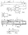
- Fig. 1 shows a side view of a percussion instrument with an elongated.
- Handle 1 which merges at its front, angled end into a head housing 2, from which a test head 3 of a rocker arm protrudes, which can be seen in more detail in the following figures, protrudes from the end.
- a supply hose 5 is connected by means of a connection fitting 4 and contains supply lines 6, 7 for a circuit arrangement to be explained in more detail.
- the end face 10 of the head housing 2 contains two light sources 11 (FIG. 2) on the circumference, which are focused in such a way that they deliver focused light on the test object (tooth), in the form of a circular light spot in planes transverse to the longitudinal axis of the test head 3, that is, parallel to the end face 10 of the head housing 2.
- the feed line 6 is connected to control electronics 12, which is shown in more detail in FIG. 5 and periodically supplies current pulses to a drive arranged in the interior of the handle 1.
- FIG. 3 shows the instrument according to FIG. 1 in longitudinal section.
- an elongated rocker arm 19 containing the test head 3 is movably mounted by means of an axle bearing 18 extending transversely to the longitudinal axis of the instrument.
- the bearings are located in the center of gravity of the rocker arm using almost friction-free bearings (tip bearings or ball bearings).
- the bearing divides the rocker arm 19 into a rear section 19a and a front section 19b which receives the test head 3.
- the test head 3 is angled almost 90 ° with respect to the rocker arm 19 and is crowned at its front end.
- the rocker arm section 19b is relatively long compared to the rear section 19a, as a result of which the test head 3 describes an almost rectilinear movement in the direction of the arrow in the region of the stroke of approximately 2 to 8 mm required for use.
- An acceleration sensor 20 is attached to the test head 3, that is to say in the immediate vicinity of the object to be tested; whose feed line 7 is attached to the axle bearing 18 in or on the rocker arm 19 and in the immediate vicinity of the bearing axis 18 out of the movable rocker arm out to a connecting member 21 arranged on the housing 17.
- the arrangement of the acceleration sensor 20 in the immediate vicinity of the test object has the advantage that, after the greatest movement takes place here, the highest acceleration signal can be tapped.
- the accelerometer can therefore be made very small.
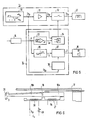
- FIG. 4 A particularly advantageous arrangement and design of an accelerometer is shown in FIG. 4.
- the accelerometer here consists of two piezoceramic elements 22 arranged one above the other, which subdivide the test head 3 into a section 3a containing the test tip with a relatively small mass and a section 3b which merges into the rocker arm section 19b with a considerably larger mass compared to section 3a . If the test head 3 impacts the object to be tested, almost the entire mass of the rocker arm acts as an inertial force on the piezoelectric elements. As a result, a useful signal increased by several powers of ten can be taken off via the feed line 7.
- a leaf spring 24 fastened in the housing 17 is provided, which presses against the rocker arm section 19b by means of a push pin 25 fastened to the slide 8 and thus pushes the rocker arm out of the rest position shown to the required Ge accelerated towards speed. If the speed is reached, the leaf spring 24 is blocked by a stop 26 arranged on the side of the rocking lever on the housing, as a result of which it is decoupled from the rocking lever. The rocker arm then moves free of force and at constant speed in free flight until it hits the test object or against an end stop.
- the rocker arm 19 is returned to its starting position by means of an electromagnet 27, which is advantageously arranged corresponding to the rocker arm section 19a and is controlled by means of control electronics with current pulses.
- the leaf spring 24 can be more or less pretensioned and thus the speed of the rocker arm can be influenced for the forward movement.
- the aforementioned drive is extremely simple and requires practically no major control effort.
- the control electronics 12 contains a pulse generator 30, which delivers a positive signal (+ U s p) for a forward movement of the plunger to the drive coil 27 and a negative signal (- U s p) for the backward movement.
- the subsequent amplifier stage 31 with the switch 32 correspondingly switches the current for the drive coil 27.
- the switch 32 interrupts the drive current during the forward movement (clock I of the pulse generator 30) when the rocker arm 19 has reached its desired speed.
- the speed signal obtained from the integrating stage 14 is compared in a target / actual value comparator 33 with a predetermined target value.
- a switch command 34 opens the switch 32 when the speed difference (A v) is zero and the pulse generator voltage is greater than zero.
- the speed signal v is simultaneously fed to a limit detector 35, which measures exceeding the permissible deviations from the target speed during the free-flight phase of the rocker arm (clock II of the pulse generator 30) and in this case via the display unit (signal generator) 16, the z. B. in the form of the indicator lamp 9 (Fig. 1) can be attached to the handle, the user of the handpiece optically or acoustically indicates an impermissible deviation.
- FIG. 6 shows an embodiment in which the forward movement also takes place electromagnetically, namely by means of an electromagnet 38 which is arranged corresponding to the rocker arm section 19b.
- an electromagnet 38 which is arranged corresponding to the rocker arm section 19b.
- the control of the coil current for the two electromagnets 27, 38 takes place via a pulse generator, which alternately supplies the two electromagnets with current pulses, as a result of which the oscillating lever executes the oscillating movement already explained.
- the speed of movement in the direction of impact can be influenced by an electrical actuator 39 which is switched on in the circuit of the drive coil 38.
- one or more light sources in the form of miniature incandescent lamps or a light guide can be provided in the vicinity of the test head 3 in or on the housing.
- the light sources are arranged in such a way that the emerging light beam is sharply focused and appears on the test object when the end face 10 (FIG. 1) of the instrument runs parallel to the object as a round light spot. The user can thus see whether he is holding the instrument in such a way that the impact movement is perpendicular to the tooth axis. In the event of deviations from the vertical, the light spot becomes elliptical, which indicates to the user that he has to correct his instrument posture.
Landscapes
- Health & Medical Sciences (AREA)
- Life Sciences & Earth Sciences (AREA)
- Physics & Mathematics (AREA)
- General Health & Medical Sciences (AREA)
- Engineering & Computer Science (AREA)
- Public Health (AREA)
- Biomedical Technology (AREA)
- Biophysics (AREA)
- Veterinary Medicine (AREA)
- Animal Behavior & Ethology (AREA)
- Molecular Biology (AREA)
- Heart & Thoracic Surgery (AREA)
- Chemical & Material Sciences (AREA)
- Pathology (AREA)
- Surgery (AREA)
- Medical Informatics (AREA)
- Dentistry (AREA)
- Analytical Chemistry (AREA)
- Biochemistry (AREA)
- General Physics & Mathematics (AREA)
- Immunology (AREA)
- Oral & Maxillofacial Surgery (AREA)
- Physiology (AREA)
- Epidemiology (AREA)
- Medicinal Chemistry (AREA)
- Bioinformatics & Cheminformatics (AREA)
- Electromagnetism (AREA)
- Anesthesiology (AREA)
- Dental Tools And Instruments Or Auxiliary Dental Instruments (AREA)
- Apparatuses For Generation Of Mechanical Vibrations (AREA)
- Electrophonic Musical Instruments (AREA)
- Investigating Strength Of Materials By Application Of Mechanical Stress (AREA)
Priority Applications (1)
| Application Number | Priority Date | Filing Date | Title |
|---|---|---|---|
| AT83103681T ATE22177T1 (de) | 1982-04-26 | 1983-04-15 | Perkussionsinstrument. |
Applications Claiming Priority (2)
| Application Number | Priority Date | Filing Date | Title |
|---|---|---|---|
| DE19823215498 DE3215498A1 (de) | 1982-04-26 | 1982-04-26 | Perkussionsinstrument |
| DE3215498 | 1982-04-26 |
Publications (2)
| Publication Number | Publication Date |
|---|---|
| EP0093896A1 EP0093896A1 (de) | 1983-11-16 |
| EP0093896B1 true EP0093896B1 (de) | 1986-09-10 |
Family
ID=6161964
Family Applications (1)
| Application Number | Title | Priority Date | Filing Date |
|---|---|---|---|
| EP83103681A Expired EP0093896B1 (de) | 1982-04-26 | 1983-04-15 | Perkussionsinstrument |
Country Status (5)
| Country | Link |
|---|---|
| US (1) | US4482324A (enExample) |
| EP (1) | EP0093896B1 (enExample) |
| JP (1) | JPS58192535A (enExample) |
| AT (1) | ATE22177T1 (enExample) |
| DE (2) | DE3215498A1 (enExample) |
Families Citing this family (22)
| Publication number | Priority date | Publication date | Assignee | Title |
|---|---|---|---|---|
| GB8431323D0 (en) * | 1984-12-12 | 1985-01-23 | Warin C C | Investigating muscles/joints |
| US4689011A (en) * | 1984-12-13 | 1987-08-25 | Siemens Aktiengesellschaft | Dental percussion instrument |
| GB8629147D0 (en) * | 1986-12-05 | 1987-01-14 | Pathreal Ltd | Dental instrument |
| DE3714966A1 (de) * | 1987-05-01 | 1988-11-10 | Mecron Med Prod Gmbh | Vorrichtung zum messen der kraftschluessigen verbindung einer zementfrei implantierbaren schaftprothese mit einem knochenschaft |
| US5518008A (en) * | 1994-08-25 | 1996-05-21 | Spectral Sciences Research Corporation | Structural analyzer, in particular for medical implants |
| EE03374B1 (et) * | 1996-03-27 | 2001-04-16 | Tartu �likool | Meetod ja seade pehmete bioloogiliste kudede omavõnkumise registreerimiseks - müomeeter |
| SE508338C2 (sv) * | 1996-07-04 | 1998-09-28 | Lars G Petersson | Förfarande och anordning för mätning av elasticitet |
| DE59610630D1 (de) * | 1996-11-01 | 2003-09-04 | Kerrhawe Sa Bioggio | Paradontalsonde |
| US6120466A (en) * | 1996-12-27 | 2000-09-19 | James C. Earthman | System and method for quantitative measurements of energy damping capacity |
| US5951292A (en) * | 1998-09-18 | 1999-09-14 | Lee; Sheng Yang | Method of detecting periodontal disease by detecting the natural frequency of a tooth. |
| SE520705C2 (sv) | 2001-12-17 | 2003-08-12 | Electrolux Ab | Upphängningsögla |
| US6997887B2 (en) * | 2002-09-27 | 2006-02-14 | Earthman James C | Evaluation of reflected time-energy profile for determination of damping capacity |
| US7008385B2 (en) * | 2002-09-27 | 2006-03-07 | Earthman James C | Evaluation of reflected time-energy profile for evaluation of osseointegration and density |
| TWI238053B (en) * | 2002-11-19 | 2005-08-21 | Miracle One Technology Co Ltd | Device for detecting stability of tooth or artificial implant |
| DE10318579A1 (de) * | 2003-04-24 | 2004-11-25 | Gernot Prof. Dr. Fischer | Kariessensor |
| US8448516B2 (en) | 2006-08-17 | 2013-05-28 | Covenant Health | Apparatus and method for assessing percutaneous implant integrity |
| WO2011160102A2 (en) | 2010-06-19 | 2011-12-22 | Perimetrics, Llc | System and method for determining structural characteristics of an object |
| US9869606B2 (en) | 2011-06-18 | 2018-01-16 | Perimetrics, Llc | System and method for determining structural characteristics of an object |
| ES2744703T3 (es) * | 2011-12-16 | 2020-02-26 | Perimetrics Llc | Sistema de determinación de características estructurales de un objeto |
| CN110139625A (zh) | 2016-12-30 | 2019-08-16 | 佩里梅特里克斯有限责任公司 | 用于确定对象的结构特性的系统和方法 |
| EP4354112B1 (en) * | 2017-12-30 | 2025-09-10 | Perimetrics, Inc. | Determination of structural characteristics of an object |
| DE102019204071A1 (de) * | 2019-03-25 | 2020-10-01 | Robert Bosch Gmbh | Verfahren zur Erkennung eines ersten Betriebszustandes einer Handwerkzeugmaschine |
Family Cites Families (16)
| Publication number | Priority date | Publication date | Assignee | Title |
|---|---|---|---|---|
| US734387A (en) * | 1903-07-21 | A J Woodworth | Electric hammer. | |
| US165701A (en) * | 1875-07-20 | Improvement | ||
| DE498728C (de) * | 1930-05-26 | Siemens Schuckertwerke Akt Ges | Elektromagnetisches Schlaggeraet | |
| US2339460A (en) * | 1942-12-08 | 1944-01-18 | Frank J Cozzoli | Tube testing means |
| US3094115A (en) * | 1960-06-08 | 1963-06-18 | Herbert S Polin | Tooth mobility indicator |
| US3653373A (en) * | 1970-01-19 | 1972-04-04 | Steven C Batterman | Apparatus for acoustically determining periodontal health |
| US3683503A (en) * | 1971-02-26 | 1972-08-15 | Erwin Klein | Dental illumination device |
| DE2162683C3 (de) * | 1971-12-17 | 1980-09-04 | Hugo Sachs Elektronik Kg, 7801 March | Einrichtung zur Messung des Weges eines Meßobjektes bei einer am Meßobjekt wirkenden Kraft |
| US4034476A (en) * | 1974-06-10 | 1977-07-12 | Johnson Robert J | Apparatus and method for determining tooth mobility |
| US4058115A (en) * | 1974-11-06 | 1977-11-15 | Forster F M O | Method and apparatus for examining human periodontal tissues |
| US3972122A (en) * | 1975-02-18 | 1976-08-03 | Sutter James E | Dental router |
| DE2617779C2 (de) * | 1976-04-23 | 1982-02-11 | Fraunhofer-Gesellschaft zur Förderung der angewandten Forschung e.V., 8000 München | Perkussionsinstrument für Diagnose- und Prüfzwecke |
| DE2733081A1 (de) * | 1977-07-22 | 1979-02-15 | Sachs Elektronik Kg Hugo | Schaltungsanordnung zum messen von zahnauslenkungen |
| DE2853252A1 (de) * | 1978-12-09 | 1980-06-19 | Walter Frenkel | Elektrisches perkussionsgeraet |
| US4289023A (en) * | 1979-09-19 | 1981-09-15 | Schlumberger Technology Corp. | Percussion method and apparatus for the investigation of a casing cement in a borehole |
| US4340069A (en) * | 1979-10-17 | 1982-07-20 | Yeaple Corporation | Force-sensitive probe and method of use |
-
1982
- 1982-04-26 DE DE19823215498 patent/DE3215498A1/de not_active Withdrawn
-
1983
- 1983-03-30 US US06/480,320 patent/US4482324A/en not_active Expired - Fee Related
- 1983-04-15 EP EP83103681A patent/EP0093896B1/de not_active Expired
- 1983-04-15 AT AT83103681T patent/ATE22177T1/de not_active IP Right Cessation
- 1983-04-15 DE DE8383103681T patent/DE3365984D1/de not_active Expired
- 1983-04-25 JP JP58072768A patent/JPS58192535A/ja active Granted
Also Published As
| Publication number | Publication date |
|---|---|
| JPS58192535A (ja) | 1983-11-10 |
| US4482324A (en) | 1984-11-13 |
| JPS6366534B2 (enExample) | 1988-12-21 |
| ATE22177T1 (de) | 1986-09-15 |
| EP0093896A1 (de) | 1983-11-16 |
| DE3365984D1 (en) | 1986-10-16 |
| DE3215498A1 (de) | 1983-10-27 |
Similar Documents
| Publication | Publication Date | Title |
|---|---|---|
| EP0093896B1 (de) | Perkussionsinstrument | |
| EP0093895B1 (de) | Perkussionsinstrument | |
| DE2337015C2 (de) | Vorrichtung zur optischen Abtastung einer um eine vertikale Rotationsachse sich drehenden Platte | |
| WO2003056303A1 (de) | Härtemessgerät mit einem gehäuse und einem eindringkörper, insbesondere handgerät | |
| EP0298262A1 (de) | Höhenmessgerät | |
| DE2617779C2 (de) | Perkussionsinstrument für Diagnose- und Prüfzwecke | |
| DE102009017819A1 (de) | Dentale oder medizinische Kamera | |
| EP0351714A2 (de) | Lagerung für Tastköpfe | |
| EP0379682A1 (de) | Tastkopf vom schaltenden Typ | |
| EP0163070A2 (de) | Zahnmesstaster | |
| DE3135180C2 (enExample) | ||
| DE2939901A1 (de) | Vorrichtung zum pruefen von elektrischen kontakten | |
| DE4132724C2 (de) | Vorschubgerät | |
| CH679889A5 (enExample) | ||
| DE3115711A1 (de) | "perkussionsinstrument fuer diagnose- und pruefzwecke" | |
| DE4129433C2 (de) | Prüfeinrichtung zur Prüfung von Schmiermittel- und/oder Werkstoffeigenschaften | |
| DD288872A5 (de) | Einkoordinatenmessgeraet | |
| DE3219766A1 (de) | Messeinrichtung und verwendung derselben | |
| EP0258588A2 (de) | Optisch arbeitendes Oberflächenprüfgerät | |
| DE2837094A1 (de) | Messumformer mit einem tastfuehler, insbesondere messvorrichtung fuer die justierung von kontaktfedern | |
| DE20120127U1 (de) | Einrichtung zur Abtastung der Gestalt, insbesondere der Rauheit einer Oberfläche eines Werkstücks | |
| DE102004001675B4 (de) | Verfahren und Vorrichtung zum Messen des Innendruckes eines elastischen Prüfkörpers, insbesondere zum Messen des Augeninnendruckes | |
| AT162545B (de) | Vorrichtung zum Messen der Härte kleiner Körper | |
| DE1913886C (de) | Verfahren zum regelbaren Dämpfen der Bewegung eines mittels eines Führungsorganes geführten beweglichen Organes eines Meßinstruments und Meßgerät zur Durchführung des Verfahrens | |
| DD285833A5 (de) | Mikrohaertepruefeinrichtung |
Legal Events
| Date | Code | Title | Description |
|---|---|---|---|
| PUAI | Public reference made under article 153(3) epc to a published international application that has entered the european phase |
Free format text: ORIGINAL CODE: 0009012 |
|
| AK | Designated contracting states |
Designated state(s): AT CH DE FR GB IT LI SE |
|
| 17P | Request for examination filed |
Effective date: 19840105 |
|
| GRAA | (expected) grant |
Free format text: ORIGINAL CODE: 0009210 |
|
| RAP1 | Party data changed (applicant data changed or rights of an application transferred) |
Owner name: LUKAS, DIETER, DIPL.-PHYS. Owner name: SCHULTE, WILLI, PROF. DR. Owner name: FRAUNHOFER-GESELLSCHAFT ZUR FOERDERUNG DER ANGEWA Owner name: SIEMENS AKTIENGESELLSCHAFT BERLIN UND MUENCHEN |
|
| AK | Designated contracting states |
Kind code of ref document: B1 Designated state(s): AT CH DE FR GB IT LI SE |
|
| REF | Corresponds to: |
Ref document number: 22177 Country of ref document: AT Date of ref document: 19860915 Kind code of ref document: T |
|
| REF | Corresponds to: |
Ref document number: 3365984 Country of ref document: DE Date of ref document: 19861016 |
|
| ET | Fr: translation filed | ||
| ITF | It: translation for a ep patent filed | ||
| PLBE | No opposition filed within time limit |
Free format text: ORIGINAL CODE: 0009261 |
|
| STAA | Information on the status of an ep patent application or granted ep patent |
Free format text: STATUS: NO OPPOSITION FILED WITHIN TIME LIMIT |
|
| 26N | No opposition filed | ||
| PG25 | Lapsed in a contracting state [announced via postgrant information from national office to epo] |
Ref country code: GB Effective date: 19880415 |
|
| PG25 | Lapsed in a contracting state [announced via postgrant information from national office to epo] |
Ref country code: SE Effective date: 19880416 |
|
| GBPC | Gb: european patent ceased through non-payment of renewal fee | ||
| ITTA | It: last paid annual fee | ||
| EUG | Se: european patent has lapsed |
Ref document number: 83103681.9 Effective date: 19890726 |
|
| PGFP | Annual fee paid to national office [announced via postgrant information from national office to epo] |
Ref country code: AT Payment date: 19950324 Year of fee payment: 13 |
|
| PGFP | Annual fee paid to national office [announced via postgrant information from national office to epo] |
Ref country code: FR Payment date: 19950426 Year of fee payment: 13 |
|
| PGFP | Annual fee paid to national office [announced via postgrant information from national office to epo] |
Ref country code: DE Payment date: 19950621 Year of fee payment: 13 |
|
| PGFP | Annual fee paid to national office [announced via postgrant information from national office to epo] |
Ref country code: CH Payment date: 19950718 Year of fee payment: 13 |
|
| PG25 | Lapsed in a contracting state [announced via postgrant information from national office to epo] |
Ref country code: AT Effective date: 19960415 |
|
| PG25 | Lapsed in a contracting state [announced via postgrant information from national office to epo] |
Ref country code: LI Effective date: 19960430 Ref country code: CH Effective date: 19960430 |
|
| REG | Reference to a national code |
Ref country code: CH Ref legal event code: PL |
|
| PG25 | Lapsed in a contracting state [announced via postgrant information from national office to epo] |
Ref country code: FR Effective date: 19961227 |
|
| PG25 | Lapsed in a contracting state [announced via postgrant information from national office to epo] |
Ref country code: DE Effective date: 19970101 |
|
| REG | Reference to a national code |
Ref country code: FR Ref legal event code: ST |