EP0093896B1 - Percussion apparatus - Google Patents
Percussion apparatus Download PDFInfo
- Publication number
- EP0093896B1 EP0093896B1 EP83103681A EP83103681A EP0093896B1 EP 0093896 B1 EP0093896 B1 EP 0093896B1 EP 83103681 A EP83103681 A EP 83103681A EP 83103681 A EP83103681 A EP 83103681A EP 0093896 B1 EP0093896 B1 EP 0093896B1
- Authority
- EP
- European Patent Office
- Prior art keywords
- rocking lever
- drive
- testing head
- percussion apparatus
- percussion
- Prior art date
- Legal status (The legal status is an assumption and is not a legal conclusion. Google has not performed a legal analysis and makes no representation as to the accuracy of the status listed.)
- Expired
Links
Images
Classifications
-
- A—HUMAN NECESSITIES
- A61—MEDICAL OR VETERINARY SCIENCE; HYGIENE
- A61B—DIAGNOSIS; SURGERY; IDENTIFICATION
- A61B9/00—Instruments for examination by percussion; Pleximeters
- A61B9/005—Electric apparatus for detecting reflex action, e.g. monitoring depth of anaesthesia
-
- A—HUMAN NECESSITIES
- A61—MEDICAL OR VETERINARY SCIENCE; HYGIENE
- A61B—DIAGNOSIS; SURGERY; IDENTIFICATION
- A61B5/00—Measuring for diagnostic purposes; Identification of persons
- A61B5/103—Detecting, measuring or recording devices for testing the shape, pattern, colour, size or movement of the body or parts thereof, for diagnostic purposes
- A61B5/11—Measuring movement of the entire body or parts thereof, e.g. head or hand tremor, mobility of a limb
- A61B5/1104—Measuring movement of the entire body or parts thereof, e.g. head or hand tremor, mobility of a limb induced by stimuli or drugs
-
- A—HUMAN NECESSITIES
- A61—MEDICAL OR VETERINARY SCIENCE; HYGIENE
- A61B—DIAGNOSIS; SURGERY; IDENTIFICATION
- A61B9/00—Instruments for examination by percussion; Pleximeters
-
- A—HUMAN NECESSITIES
- A61—MEDICAL OR VETERINARY SCIENCE; HYGIENE
- A61C—DENTISTRY; APPARATUS OR METHODS FOR ORAL OR DENTAL HYGIENE
- A61C19/00—Dental auxiliary appliances
- A61C19/04—Measuring instruments specially adapted for dentistry
-
- G—PHYSICS
- G01—MEASURING; TESTING
- G01N—INVESTIGATING OR ANALYSING MATERIALS BY DETERMINING THEIR CHEMICAL OR PHYSICAL PROPERTIES
- G01N3/00—Investigating strength properties of solid materials by application of mechanical stress
- G01N3/30—Investigating strength properties of solid materials by application of mechanical stress by applying a single impulsive force, e.g. by falling weight
- G01N3/303—Investigating strength properties of solid materials by application of mechanical stress by applying a single impulsive force, e.g. by falling weight generated only by free-falling weight
-
- G—PHYSICS
- G01—MEASURING; TESTING
- G01N—INVESTIGATING OR ANALYSING MATERIALS BY DETERMINING THEIR CHEMICAL OR PHYSICAL PROPERTIES
- G01N3/00—Investigating strength properties of solid materials by application of mechanical stress
- G01N3/30—Investigating strength properties of solid materials by application of mechanical stress by applying a single impulsive force, e.g. by falling weight
- G01N3/317—Investigating strength properties of solid materials by application of mechanical stress by applying a single impulsive force, e.g. by falling weight generated by electromagnetic means
-
- A—HUMAN NECESSITIES
- A61—MEDICAL OR VETERINARY SCIENCE; HYGIENE
- A61B—DIAGNOSIS; SURGERY; IDENTIFICATION
- A61B5/00—Measuring for diagnostic purposes; Identification of persons
- A61B5/103—Detecting, measuring or recording devices for testing the shape, pattern, colour, size or movement of the body or parts thereof, for diagnostic purposes
- A61B5/11—Measuring movement of the entire body or parts thereof, e.g. head or hand tremor, mobility of a limb
- A61B5/1111—Detecting tooth mobility
-
- A—HUMAN NECESSITIES
- A61—MEDICAL OR VETERINARY SCIENCE; HYGIENE
- A61B—DIAGNOSIS; SURGERY; IDENTIFICATION
- A61B5/00—Measuring for diagnostic purposes; Identification of persons
- A61B5/68—Arrangements of detecting, measuring or recording means, e.g. sensors, in relation to patient
- A61B5/6801—Arrangements of detecting, measuring or recording means, e.g. sensors, in relation to patient specially adapted to be attached to or worn on the body surface
- A61B5/6813—Specially adapted to be attached to a specific body part
- A61B5/6814—Head
- A61B5/682—Mouth, e.g., oral cavity; tongue; Lips; Teeth
-
- G—PHYSICS
- G01—MEASURING; TESTING
- G01N—INVESTIGATING OR ANALYSING MATERIALS BY DETERMINING THEIR CHEMICAL OR PHYSICAL PROPERTIES
- G01N2203/00—Investigating strength properties of solid materials by application of mechanical stress
- G01N2203/0058—Kind of property studied
- G01N2203/0089—Biorheological properties
Definitions
- the invention relates. on a percussion instrument with a movably mounted plunger, which contains a test head at one end and which accelerates from a starting position to a defined speed by means of a drive, then, uncoupled from the drive, moves towards a test object at constant speed in free flight and is returned to its starting position with the help of a magnetic field.
- the plunger is mounted so that it can be moved back and forth in the axial direction of the instrument.
- the plunger is accelerated to a certain speed by a spiral spring arranged in the front part of the instrument containing the test head and held in the starting position by means of a magnetic coil.
- the plunger releases from the spring and, guided in bearings, flies towards the object under test in free flight at a theoretically constant speed.
- the ram is thrown back towards the starting position by the counter impulse.
- the coil receives a current pulse.
- the resulting magnetic field brings the plunger back to its original position and the spring is tensioned again.
- An accelerometer connected to the plunger via a flexible cable forms a change in speed when the plunger impacts the object to be tested. This change in speed can be evaluated during the deflection and reset movement for specific test and diagnostic purposes in an evaluation electronics connected to the accelerometer; in dentistry, for example, to measure tooth mobility or the degree of loosening of a tooth. The time within which the tooth to be tested returns to its starting position after the pulse has been given gives z. B. Information about the condition of the tooth holding apparatus.
- Known percussion instruments of this type have various disadvantages.
- the tappet which in the known instrument performs a linear flight movement running in the axial direction of the instrument and is said to maintain a constant speed, is influenced by the force of gravity. If the position of the instrument deviates from the horizontal, the flight speed of the plunger changes, which falsifies the measurement results. To prevent this, the instrument would have to be kept absolutely horizontal, which would require a high degree of concentration from the user, which would be inappropriate for this purpose.
- test objects e.g. B. the teeth with the known instrument can only be pushed from the side from which the instrument can be fed to the object in the horizontal position.
- Test objects that are not accessible in the direction in which the instrument is fed to the object to be tested can therefore not or not reliably be measured.
- the teeth in the molar range can therefore not or only poorly be detected with the known percussion instrument.
- the accelerometer provided in the known instrument is arranged on the end of the plunger facing away from the test head and is connected to the evaluation electronics via a highly flexible feed line. After the supply line has to take part or compensate for practically the entire tappet movement, premature wear (breakage) of the line can occur.
- the acceleration signal obtained with the accelerometer of the known type is also relatively small and has to be amplified by complex circuit measures.
- Another disadvantage is the fact that the tappet mounted in plain bearings is braked by the frictional forces in the bearing. These frictional forces can change greatly due to external influences, e.g. B. by moisture, dust, etc.
- the plunger speed is subject to certain changes, which also falsify the measurement results.
- the plunger is designed as an elongated rocking lever, which is movably supported in its center of gravity about an axis lying transversely to the longitudinal axis of the instrument, to form the test head at an angle, preferably at right angles, to the longitudinal axis of the rocking lever and on Test head to attach a known accelerometer.
- the proposed percussion instrument works independently of the position and is not influenced by gravity.
- the arrangement of an accelerometer in the front section of the plunger containing the test head has the advantage that a considerably larger acceleration signal is obtained when hitting the object to be tested and a lower interference signal during the backward movement than before. After the tappet is stored in the center of gravity with practically no friction, the bearing friction when the tappet moves is practically negligible.
- the proposed arrangement also makes it possible, when using an accelerometer, to guide the necessary supply cable in such a way that it is practically not loaded when the plunger swings.
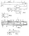
- Fig. 1 shows a side view of a percussion instrument with an elongated.
- Handle 1 which merges at its front, angled end into a head housing 2, from which a test head 3 of a rocker arm protrudes, which can be seen in more detail in the following figures, protrudes from the end.
- a supply hose 5 is connected by means of a connection fitting 4 and contains supply lines 6, 7 for a circuit arrangement to be explained in more detail.
- the end face 10 of the head housing 2 contains two light sources 11 (FIG. 2) on the circumference, which are focused in such a way that they deliver focused light on the test object (tooth), in the form of a circular light spot in planes transverse to the longitudinal axis of the test head 3, that is, parallel to the end face 10 of the head housing 2.
- the feed line 6 is connected to control electronics 12, which is shown in more detail in FIG. 5 and periodically supplies current pulses to a drive arranged in the interior of the handle 1.
- FIG. 3 shows the instrument according to FIG. 1 in longitudinal section.
- an elongated rocker arm 19 containing the test head 3 is movably mounted by means of an axle bearing 18 extending transversely to the longitudinal axis of the instrument.
- the bearings are located in the center of gravity of the rocker arm using almost friction-free bearings (tip bearings or ball bearings).
- the bearing divides the rocker arm 19 into a rear section 19a and a front section 19b which receives the test head 3.
- the test head 3 is angled almost 90 ° with respect to the rocker arm 19 and is crowned at its front end.
- the rocker arm section 19b is relatively long compared to the rear section 19a, as a result of which the test head 3 describes an almost rectilinear movement in the direction of the arrow in the region of the stroke of approximately 2 to 8 mm required for use.
- An acceleration sensor 20 is attached to the test head 3, that is to say in the immediate vicinity of the object to be tested; whose feed line 7 is attached to the axle bearing 18 in or on the rocker arm 19 and in the immediate vicinity of the bearing axis 18 out of the movable rocker arm out to a connecting member 21 arranged on the housing 17.
- the arrangement of the acceleration sensor 20 in the immediate vicinity of the test object has the advantage that, after the greatest movement takes place here, the highest acceleration signal can be tapped.
- the accelerometer can therefore be made very small.
- FIG. 4 A particularly advantageous arrangement and design of an accelerometer is shown in FIG. 4.
- the accelerometer here consists of two piezoceramic elements 22 arranged one above the other, which subdivide the test head 3 into a section 3a containing the test tip with a relatively small mass and a section 3b which merges into the rocker arm section 19b with a considerably larger mass compared to section 3a . If the test head 3 impacts the object to be tested, almost the entire mass of the rocker arm acts as an inertial force on the piezoelectric elements. As a result, a useful signal increased by several powers of ten can be taken off via the feed line 7.
- a leaf spring 24 fastened in the housing 17 is provided, which presses against the rocker arm section 19b by means of a push pin 25 fastened to the slide 8 and thus pushes the rocker arm out of the rest position shown to the required Ge accelerated towards speed. If the speed is reached, the leaf spring 24 is blocked by a stop 26 arranged on the side of the rocking lever on the housing, as a result of which it is decoupled from the rocking lever. The rocker arm then moves free of force and at constant speed in free flight until it hits the test object or against an end stop.
- the rocker arm 19 is returned to its starting position by means of an electromagnet 27, which is advantageously arranged corresponding to the rocker arm section 19a and is controlled by means of control electronics with current pulses.
- the leaf spring 24 can be more or less pretensioned and thus the speed of the rocker arm can be influenced for the forward movement.
- the aforementioned drive is extremely simple and requires practically no major control effort.
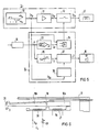
- the control electronics 12 contains a pulse generator 30, which delivers a positive signal (+ U s p) for a forward movement of the plunger to the drive coil 27 and a negative signal (- U s p) for the backward movement.
- the subsequent amplifier stage 31 with the switch 32 correspondingly switches the current for the drive coil 27.
- the switch 32 interrupts the drive current during the forward movement (clock I of the pulse generator 30) when the rocker arm 19 has reached its desired speed.
- the speed signal obtained from the integrating stage 14 is compared in a target / actual value comparator 33 with a predetermined target value.
- a switch command 34 opens the switch 32 when the speed difference (A v) is zero and the pulse generator voltage is greater than zero.
- the speed signal v is simultaneously fed to a limit detector 35, which measures exceeding the permissible deviations from the target speed during the free-flight phase of the rocker arm (clock II of the pulse generator 30) and in this case via the display unit (signal generator) 16, the z. B. in the form of the indicator lamp 9 (Fig. 1) can be attached to the handle, the user of the handpiece optically or acoustically indicates an impermissible deviation.
- FIG. 6 shows an embodiment in which the forward movement also takes place electromagnetically, namely by means of an electromagnet 38 which is arranged corresponding to the rocker arm section 19b.
- an electromagnet 38 which is arranged corresponding to the rocker arm section 19b.
- the control of the coil current for the two electromagnets 27, 38 takes place via a pulse generator, which alternately supplies the two electromagnets with current pulses, as a result of which the oscillating lever executes the oscillating movement already explained.
- the speed of movement in the direction of impact can be influenced by an electrical actuator 39 which is switched on in the circuit of the drive coil 38.
- one or more light sources in the form of miniature incandescent lamps or a light guide can be provided in the vicinity of the test head 3 in or on the housing.
- the light sources are arranged in such a way that the emerging light beam is sharply focused and appears on the test object when the end face 10 (FIG. 1) of the instrument runs parallel to the object as a round light spot. The user can thus see whether he is holding the instrument in such a way that the impact movement is perpendicular to the tooth axis. In the event of deviations from the vertical, the light spot becomes elliptical, which indicates to the user that he has to correct his instrument posture.
Abstract
Description
Die Erfindung bezieht . sich auf ein Perkussionsinstrument mit einem beweglich gelagerten Stößel, der an seinem einen Ende einen Prüfkopf enthält und der mittels eines Antriebes aus einer Ausgangsstellung auf eine definierte Geschwindigkeit beschleunigt, danach, vom Antrieb abgekuppelt, mit gleichbleibender Geschwindigkeit im freien Flug auf ein Prüfobjekt zu bewegt und mit Hilfe eines Magnetfeldes wieder in seine Ausgangslage zurückgestellt wird.The invention relates. on a percussion instrument with a movably mounted plunger, which contains a test head at one end and which accelerates from a starting position to a defined speed by means of a drive, then, uncoupled from the drive, moves towards a test object at constant speed in free flight and is returned to its starting position with the help of a magnetic field.
Bei einem bekannten solchen Instrument (DE-OS-26 17779) ist der Stößel in Achsrichtung des Instrumentes hin- und herbewegbar gelagert. Der Stößel wird durch eine im vorderen, den Prüfkopf enthaltenden Teil des Instrumentes angeordnete und mittels Magnetspule in der Ausgangsstellung gehaltene Spiralfeder auf eine bestimmte Geschwindigkeit beschleunigt. Nach vollständiger Entspannung der Feder löst sich der Stößel von der Feder und fliegt, in Lagern geführt, im freien Flug mit theoretisch konstanter Geschwindigkeit auf das zu prüfende Objekt zu. Nach Aufprall auf das Objekt wird durch den dabei entstehenden Gegenimpuls der Stößel wieder in Richtung Ausgangsstellung zurückgeworfen. Gegen Ende der Rückflugbewegung erhält die Spule einen Stromimpuls. Durch das dabei entstehende Magnetfeld wird der Stößel in seine Ausgangsstellung zurückgeholt und dabei die Feder erneut gespannt. Ein mit dem Stößel über ein biegeschlaff ausgebildetes Kabel verbundener Beschleunigungsaufnehmer erfaßt eine Geschwindigkeitsänderung beim Aufprall des Stößels auf das zu prüfende Objekt. Diese Geschwindigkeitsänderung kann während der Auslenk- und Rückstellbewegung für bestimmte Prüf-und Diagnosezwecke in einer mit dem Beschleunigungsaufnehmer verbundenen Auswerteelektronik ausgewertet werden ; in der Zahnheilkunde beispielsweise, um die Zahnbeweglichkeit bzw. den Lockerungsgrad eines Zahnes zu messen. Die Zeit, innerhalb der nach erfolgtem Impuls der zu prüfende Zahn wieder in seine Ausgangsstellung zurückkehrt, gibt z. B. Aufschluß über den Zustand des Zahnhalteapparates.In a known such instrument (DE-OS-26 17779), the plunger is mounted so that it can be moved back and forth in the axial direction of the instrument. The plunger is accelerated to a certain speed by a spiral spring arranged in the front part of the instrument containing the test head and held in the starting position by means of a magnetic coil. After the spring has completely relaxed, the plunger releases from the spring and, guided in bearings, flies towards the object under test in free flight at a theoretically constant speed. After impacting the object, the ram is thrown back towards the starting position by the counter impulse. Towards the end of the return flight movement, the coil receives a current pulse. The resulting magnetic field brings the plunger back to its original position and the spring is tensioned again. An accelerometer connected to the plunger via a flexible cable forms a change in speed when the plunger impacts the object to be tested. This change in speed can be evaluated during the deflection and reset movement for specific test and diagnostic purposes in an evaluation electronics connected to the accelerometer; in dentistry, for example, to measure tooth mobility or the degree of loosening of a tooth. The time within which the tooth to be tested returns to its starting position after the pulse has been given gives z. B. Information about the condition of the tooth holding apparatus.
Bekannte Perkussionsinstrumente dieser Bauart sind mit verschiedenen Nachteilen behaftet. So wird der Stößel, der bei dem bekannten Instrument eine geradlinige, in Achsrichtung des Instruments verlaufende Flugbewegung ausführt und dabei eine konstante Geschwindigkeit beibehalten soll, von der Erdanziehungskraft beeinflußt. Weicht die Lage des Instrumentes von der Waagerechten ab, so verändert sich die Fluggeschwindigkeit des Stößels, wodurch die Meßergebnisse verfälscht werden. Um diesem vorzubeugen, müßte also das Instrument absolut waagerecht gehalten werden, was vom Anwender ein hohes Maß an Konzentration erfordern würde, die für diesen Zweck unangemessen wäre.Known percussion instruments of this type have various disadvantages. The tappet, which in the known instrument performs a linear flight movement running in the axial direction of the instrument and is said to maintain a constant speed, is influenced by the force of gravity. If the position of the instrument deviates from the horizontal, the flight speed of the plunger changes, which falsifies the measurement results. To prevent this, the instrument would have to be kept absolutely horizontal, which would require a high degree of concentration from the user, which would be inappropriate for this purpose.
Ebenfalls von der Erdanziehungskraft beeinflußt ist die Vorrichtung gemäß US-A-23 39 460, bei der der Stößel als Langgestreckter Schwinghebel ausgebildet ist.The device according to US-A-23 39 460, in which the plunger is designed as an elongated rocking lever, is also influenced by the gravitational pull.
Ein weiterer Nachteil ist darin zu sehen, daß die Prüfobjekte, z. B. die Zähne, mit dem bekannten Instrument nur von der Seite aus angestoßen werden können, von der das Instrument in der waagerechten Haltung dem Objekt zuführbar ist.Another disadvantage is that the test objects, e.g. B. the teeth with the known instrument can only be pushed from the side from which the instrument can be fed to the object in the horizontal position.
Prüfobjekte, die in der Richtung, in der das Instrument an das zu prüfende Objekt zugeführt wird, nicht zugänglich sind, können deshalb nicht bzw. nicht zuverlässig gemessen werden. Bei Anwendung des Instruments zur Überprüfung der Zahnbeweglichkeit sind deshalb die im molaren Bereich liegenden Zähne mit dem bekannten Perkussionsinstrument nicht bzw. nur schlecht zu erfassen.Test objects that are not accessible in the direction in which the instrument is fed to the object to be tested can therefore not or not reliably be measured. When using the instrument for checking the tooth mobility, the teeth in the molar range can therefore not or only poorly be detected with the known percussion instrument.
Weitere Nachteile sind in der Anordnung des Beschleunigungsaufnehmers und der damit zu gewinnenden Beschleunigungssignale zu sehen. Der bei dem bekannten Instrument vorgesehene Beschleunigungsaufnehmer ist an dem dem Prüfkopf abgewandten Ende des Stößels angeordnet und über eine hochflexible Zufuhrleitung mit der Auswerteelektronik verbunden. Nachdem die Zuleitung praktisch die gesamte Stößelbewegung mitmachen bzw. ausgleichen muß, kann es zu einem vorzeitigen Verschleiß (Bruch) der Leitung kommen. Das mit dem Beschleunigungsaufnehmer der bekannten Bauart gewonnene Beschleunigungssignal ist außerdem relativ klein und muß durch aufwendige Schaltungsmaßnahmen verstärkt werden. Ein weiterer Nachteil ist darin zu sehen, daß der in Gleitlagern gelagerte Stößel von den Reibungskräften im Lager gebremst wird. Diese Reibungskräfte können sich durch äußere Einflüsse stark verändern, z. B. durch Feuchtigkeit, Staub usw. Die Stößelgeschwindigkeit ist dadurch gewissen Veränderungen unterworfen, die ebenfalls die Meßergebnisse verfälschen.Further disadvantages can be seen in the arrangement of the accelerometer and the acceleration signals to be obtained therewith. The accelerometer provided in the known instrument is arranged on the end of the plunger facing away from the test head and is connected to the evaluation electronics via a highly flexible feed line. After the supply line has to take part or compensate for practically the entire tappet movement, premature wear (breakage) of the line can occur. The acceleration signal obtained with the accelerometer of the known type is also relatively small and has to be amplified by complex circuit measures. Another disadvantage is the fact that the tappet mounted in plain bearings is braked by the frictional forces in the bearing. These frictional forces can change greatly due to external influences, e.g. B. by moisture, dust, etc. The plunger speed is subject to certain changes, which also falsify the measurement results.
Zur Beseitigung der den bekannten Perkussionsinstrumenten anhaftenden Nachteile wird erfindungsgemäß vorgeschlagen, den Stößel als langgestreckten Schwinghebel auszubilden, der in seinem Schwerpunkt um eine quer zur Längsachse des Instrumentes liegende Achse bewegbar gelagert ist, den Prüfkopf winkelig, vorzugsweise rechtwinkelig, zur Längsachse des Schwinghebels auszubilden und am Prüfkopf einen an sich bekannten Beschleunigungsaufnehmer anzubringen.In order to eliminate the disadvantages inherent in the known percussion instruments, it is proposed according to the invention to design the plunger as an elongated rocking lever, which is movably supported in its center of gravity about an axis lying transversely to the longitudinal axis of the instrument, to form the test head at an angle, preferably at right angles, to the longitudinal axis of the rocking lever and on Test head to attach a known accelerometer.
Das vorgeschlagene Perkussionsinstrument arbeitet lageunabhängig und unbeeinflußt von der Schwerkraft.The proposed percussion instrument works independently of the position and is not influenced by gravity.
Durch die winkelige Anordnung des Prüfkopfes sind Messungen auch an relativ schlecht zugänglichen Stellen, z. B. im molaren Bereich der Zähne, möglich.Due to the angular arrangement of the test head, measurements are also possible at relatively difficult to access locations, e.g. B. in the molar region of the teeth possible.
Vorteilhafte Weiterbildungen und Ausgestaltungen der Erfindung sind in den Unteransprüchen enthalten.Advantageous further developments and refinements of the invention are contained in the subclaims.
Die Anordnung eines Beschleunigungsaufnehmers im vorderen, den Prüfkopf enthaltenden Abschnitt des Stößels hat den Vorteil, daß man ein erheblich größeres Beschleunigungssignal beim Stoß auf das zu prüfende Objekt und ein geringeres Störsignal bei der Rückwärtsbewegung erhält als bisher. Nachdem der Stößel praktisch reibungsfrei im Schwerpunkt gelagert ist, ist die Lagerreibung bei der Bewegung des Stößels praktisch vernachlässigbar. Durch die vorgeschlagene Anordnung ist es auch möglich, bei Verwendung eines Beschleunigungsaufnehmers das erforderliche Zuleitungskabel so zu führen, daß dieses bei der Schwingbewegung des Stößels praktisch nicht belastet wird.The arrangement of an accelerometer in the front section of the plunger containing the test head has the advantage that a considerably larger acceleration signal is obtained when hitting the object to be tested and a lower interference signal during the backward movement than before. After the tappet is stored in the center of gravity with practically no friction, the bearing friction when the tappet moves is practically negligible. The proposed arrangement also makes it possible, when using an accelerometer, to guide the necessary supply cable in such a way that it is practically not loaded when the plunger swings.
Ausführungsbeispiele der Erfindung werden nachfolgend anhand der Zeichnung näher erläutert. Es zeigen :
- Figur 1 ein Perkussionsinstrument nach der Erfindung in einer schaubildlichen Darstellung,
Figur 2 einen Teil des Instrumentes nach Fig. 1 in einer Draufsicht,Figur 3 das Instrument nach Fig. 1 im Längsschnitt,- Figur 4 einen Teil des Schwinghebels im Längsschnitt,
Figur 5 eine Ausführungsform einer Schaltungsanordnung zur Ansteuerung des Antriebs,Figur 6 eine andere Ausführungsform des Instrumentes im Längsschnitt.
- FIG. 1 shows a percussion instrument according to the invention in a diagrammatic representation,
- FIG. 2 shows a part of the instrument according to FIG. 1 in a top view,
- 3 shows the instrument according to FIG. 1 in longitudinal section,
- FIG. 4 shows part of the rocker arm in longitudinal section,
- FIG. 5 shows an embodiment of a circuit arrangement for controlling the drive,
- Figure 6 shows another embodiment of the instrument in longitudinal section.
Die Fig. 1 zeigt in einer Seitenansicht ein Perkussionsinstrument mit einem länglichen. Handgriff 1, der an seinem vorderen, abgewinkelten Ende in ein Kopfgehäuse 2 übergeht, aus dem stirnseitig ein Prüfkopf 3 eines in den nachfolgenden Figuren noch näher ersichtlichen Schwinghebels vorsteht. An dem dem Kopfge- - häuse 2 abgewandten Ende des Handgriffes 1 ist mittels einer Anschlußarmatur 4 ein Versorgungsschlauch 5 angeschlossen, der Zuleitungen 6, 7 für eine noch näher erläuterte Schaltungsanordnung enthält.Fig. 1 shows a side view of a percussion instrument with an elongated. Handle 1, which merges at its front, angled end into a
Mit 8 ist ein von Hand betätigbarer Schieber, mit 9 eine Anzeigeleuchte bezeichnet.8 is a manually operable slide, 9 denotes an indicator light.
Die Stirnseite 10 des Kopfgehäuses 2 enthält am Umfang zwei Lichtquellen 11 (Fig. 2), die so fokussiert sind, daß sie am Prüfobjekt (Zahn) gebündeltes Licht liefern, und zwar in Form eines kreisrunden Lichtfleckes in Ebenen quer zur Längsachse des Prüfkopfes 3, also parallel zur Stirnfläche 10 des Kopfgehäuses 2.The
Die Zuleitung 6 ist mit einer Steuerelektronik 12 verbunden, die in Fig. 5 noch näher aufgezeigt ist und einem im Inneren des Handgriffes 1 angeordneten Antrieb periodisch Stromimpulse zuführt.The
Über die Leitung 7 werden die vom Prüfkopf 3 bei dessen Anschlag am zu prüfenden Objekt erhaltenen Beschleunigungssignale einerseits einer Auswerteelektronik 13 zur weiteren objektbezogenen Auswertung zugeführt, andererseits in einer Integrierstufe 14 nach der Beziehung v = b b dt in Geschwindigkeitssignale umgewandelt, die in einer Meß- und Auswerteeinrichtung 15 weiterverarbeitet werden. In einer Anzeigeeinrichtung 16 kann dem Anwender eine akustische oder optische Information gegeben werden.Via the line 7, the acceleration signals received by the
Die Fig. 3 zeigt das Instrument nach Fig. 1 im Längsschnitt. Im Gehäuse 17 des Handgriffes 1 ist mittels einer quer zur Längsachse des Instrumentes verlaufenden Achslagerung 18 ein langgestreckter, den Prüfkopf 3 enthaltender Schwinghebel 19 bewegbar gelagert. Die Lagerung erfolgt im Schwerpunkt des Schwinghebels mittels nahezu reibungsfreier Lager (Spitzenlager oder Kugellager). Die Lagerung unterteilt den Schwinghebel 19 in einen rückwärtigen Abschnitt 19a und einen vorderen, den Prüfkopf 3 aufnehmenden Abschnitt 19b. Der Prüfkopf 3 ist in bezug auf den Schwinghebel 19 nahezu um 90° abgewinkelt und an seinem vorderen Ende ballig ausgebildet. Der Schwinghebelabschnitt 19b ist im Vergleich zum rückwärtigen Abschnitt 19a relativ lang ausgebildet, wodurch der Prüfkopf 3 im Bereich des zur Anwendung erforderlichen Hubes von etwa 2 bis 8 mm eine nahezu geradlinige Bewegung in Pfeilrichtung beschreibt.3 shows the instrument according to FIG. 1 in longitudinal section. In the
Am Prüfkopf 3, also in unmittelbarer Nähe des zu prüfenden Objektes, ist ein Beschleunigungsaufnehmer 20 befestigt ; dessen Zuleitung 7 ist bis zur Achslagerung 18 im oder am Schwinghebel 19 befestigt und in unmittelbarer Nähe der Lagerachse 18 aus dem beweglichen Schwinghebel heraus zu einem am Gehäuse 17 angeordneten Anschlußglied 21 geführt. Die Anordnung des Beschleunigungsaufnehmers 20 in unmittelbarer Nähe des Prüfobjektes hat den Vorteil, daß, nachdem hier die größte Bewegung stattfindet, das höchste Beschleunigungssignal abgegriffen werden kann. Der Beschleunigungsaufnehmer kann deshalb sehr klein ausgebildet sein.An
Eine besonders vorteilhafte Anordnung und Ausbildung eines Beschleunigungsaufnehmers ist in Fig. 4 dargestellt. Der Beschleunigungsaufnehmer besteht hier aus zwei übereinander angeordneten piezokeramischen Elementen 22, die den Prüfkopf 3 in einen die Prüfspitze enthaltenden Abschnitt 3a mit relativ kleiner Masse und einen Abschnitt 3b, der in den Schwinghebelabschnitt 19b übergeht, mit im Vergleich zum Abschnitt 3a erheblich größerer Masse, unterteilen. Bei Aufprall des Prüfkopfes 3 auf das zu prüfende Objekt wird nahezu die gesamte Masse des Schwinghebels als Trägheitskraft auf die piezoelektrischen Elemente wirksam. Dadurch kann ein um mehrere Zehnerpotenzen erhöhtes Nutzsignal über die Zuleitung 7 abgenommen werden. Bei Rückführung des Schwinghebels in die Ausgangsposition und bei Anschlag an die dort befindlichen Begrenzungen wirkt infolge der relativ kleinen Masse des Abschnittes 3a, welche auf die Piezoelemente wirken, dagegen eine geringe Trägheitskraft auf die Elemente, wodurch nur ein geringfügiges Störsignal erzeugt wird.A particularly advantageous arrangement and design of an accelerometer is shown in FIG. 4. The accelerometer here consists of two
Als Antrieb für die Vorwärtsbewegung des Schwinghebels 19 ist eine im Gehäuse 17 befestigte Blattfeder 24 vorgesehen, die mittels eines am Schieber 8 befestigten Druckstiftes 25 gegen den Schwinghebelabschnitt 19b drückt und so den Schwinghebel aus der gezeichneten Ruhestellung heraus auf die erforderliche Geschwindigkeit hin beschleunigt. Ist die Geschwindigkeit erreicht, wird die Blattfeder 24 von einem seitlich des Schwinghebels am Gehäuse angeordneten Anschlag 26 blockiert, wodurch diese vom Schwinghebel abgekoppelt wird. Der Schwinghebel bewegt sich danach kräftefrei und mit konstanter Geschwindigkeit im freien Flug weiter bis er am Prüfobjekt oder gegen einen Endanschlag anschlägt.As a drive for the forward movement of the
Die Rückführung des Schwinghebels 19 in seine Ausgangsposition erfolgt mittels eines Elektromagneten 27, der vorteilhafterweise korrespondierend dem Schwinghebelabschnitt 19a angeordnet ist und mittels einer Steuerelektronik mit Stromimpulsen angesteuert wird.The
Mittels des Schiebers 8 kann die Blattfeder 24 mehr oder weniger vorgespannt und damit die Geschwindigkeit des Schwinghebels für die Vorwärtsbewegung beeinflußt werden.By means of the slide 8, the leaf spring 24 can be more or less pretensioned and thus the speed of the rocker arm can be influenced for the forward movement.
.Der vorgenannte Antrieb ist äußerst einfach und erfordert praktisch keinen größeren Steuerungsaufwand. Denkbar ist es aber auch, den Antrieb für die Vorwärtsbewegung elektromagnetisch auszuführen. Gemäß einer vorteilhaften Ausgestaltung der Erfindung wird demnach vorgeschlagen, am Ende des Schwinghebelabschnittes 19a einen Permanentmagneten 28 anzuordnen, der mit dem Ende 29 des Elektromagneten so korrespondiert, daß je nach Richtung des über die Steuerelektronik 12 gesteuerten Spulenstroms eine anziehende bzw. abstoßende Wirkung eintritt.The aforementioned drive is extremely simple and requires practically no major control effort. However, it is also conceivable to electromagnetically design the drive for the forward movement. According to an advantageous embodiment of the invention, it is therefore proposed to arrange a
Die Ansteuerung der Spule 27, die bei dieser Lösung sowohl für die Vor- als auch für die Rückwärtsbewegung des Schwinghebels 19 dient, sei anhand der Blockschaltbilder nach Fig. 1 und 5 näher erläutert.The control of the
Die Steuerelektronik 12 enthält einen Impulsgeber 30, der für eine Vorwärtsbewegung des Stößels an die Antriebsspule 27 ein positives Signal (+ Usp) und für die Rückwärtsbewegung ein negatives Signal (- Usp) liefert. Zeitlich zwischen den Phasen der Vorwärtsbewegung (I) und der Rückwärtsbewegung (111) liegt die Freiflugphase (11), in der der Schwinghebel 19 ohne zusätzlichen Antrieb nach vorne gedrückt wird. Die nachfolgende Verstärkerstufe 31 mit dem Schalter 32 schaltet entsprechend den Strom für die Antriebsspule 27. Der Schalter 32 unterbricht dabei den Antriebsstrom während der Vorwärtsbewegung (Takt I des Impulsgebers 30), wenn der Schwinghebel 19- seine Sollgeschwindigkeit erreicht hat. Dazu wird das aus der Integrierstufe 14 gewonnene Geschwindigkeitssignal in einem Soll-Istwertvergleicher 33 mit einem vorgegebenen Sollwert verglichen. Ein Schaltbefehlgeber 34 öffnet den Schalter 32, wenn die Geschwindigkeitsdifferenz (A v) Null und die Impulsgeberspannung größer als Null ist.The
Das Geschwindigkeitssignal v wird gleichzeitig einem Grenzwertmelder 35 zugeführt, der ein Überschreiten der zulässigen Abweichungen von der Sollgeschwindigkeit während der Freiflugphase des Schwinghebels (Takt II des Impulsgebers 30) mißt und in diesem Fall über die Anzeigeeinheit (Signalgeber) 16, die z. B. in Form der Anzeigelampe 9 (Fig. 1) am Handgriff angebracht sein kann, dem Benutzer des Handstückes optisch oder akustisch auf eine nicht zulässige Abweichung hinweist.The speed signal v is simultaneously fed to a
Ein Schaltbefehlgeber 36 sorgt dafür, daß das Fehlersignal vom Schalter 37 nur dann durchgeschaltet wird, wenn sich der Schwinghebel im Freiflug (Takt II des Impulsgebers) befindet. In diesem Fall ist die anliegende Spannung Usp = O.A switching
Die Fig. 6 zeigt eine Ausführungsform, bei der die Vorwärtsbewegung ebenfalls elektromagnetisch erfolgt, und zwar mittels eines Elektromagneten 38, der dem Schwinghebelabschnitt 19b korrespondierend angeordnet ist. Auch hier besteht zumindest der mit dem Elektromagneten 38 korrespondierende Teil des Schwinghebels aus weichmagnetischem Material. Die Steuerung des Spulenstroms für die beiden Elektromagnete 27, 38 erfolgt über einen Impulsgeber, der die beiden Elektromagneten wechselweise mit Stromimpulsen versorgt, wodurch der Schwinghebel die bereits erläuterte hin- und herschwingende Bewegung ausführt. Die Bewegungsgeschwindigkeit in Stoßrichtung kann durch ein elektrisches Stellglied 39, welches im Stromkreis der Antriebsspule 38 eingeschaltet ist, beeinflußt werden.FIG. 6 shows an embodiment in which the forward movement also takes place electromagnetically, namely by means of an
Wie eingangs in Betrachtung der Fig. 2 bereits angesprochen, können, um die Anwendung des Instrumentes für den Benutzer noch weiter zu vereinfachen, in Nähe des Prüfkopfes 3 im oder am Gehäuse ein oder mehrere Lichtquellen in Form von Miniaturglühlampen oder eines Lichtleiters vorgesehen sein.As already mentioned at the outset in FIG. 2, in order to simplify the use of the instrument even further for the user, one or more light sources in the form of miniature incandescent lamps or a light guide can be provided in the vicinity of the
Die Lichtquellen sind so angeordnet, daß der austretende Lichtstrahl scharf gebündelt ist und auf dem Prüfobjekt dann, wenn die Stirnfläche 10 (Fig. 1) des Instruments parallel zum Objekt verläuft, als runder Lichtfleck erscheint. Der Anwender kann so erkennen, ob er das Instrument so hält, daß die Stoßbewegung senkrecht zur Zahnachse erfolgt. Bei Abweichungen von der Senkrechten wird der Lichtfleck elliptisch, wodurch dem Anwender angezeigt wird, daß er seine Instrumentenhaltung zu korrigieren hat.The light sources are arranged in such a way that the emerging light beam is sharply focused and appears on the test object when the end face 10 (FIG. 1) of the instrument runs parallel to the object as a round light spot. The user can thus see whether he is holding the instrument in such a way that the impact movement is perpendicular to the tooth axis. In the event of deviations from the vertical, the light spot becomes elliptical, which indicates to the user that he has to correct his instrument posture.
Claims (14)
Priority Applications (1)
| Application Number | Priority Date | Filing Date | Title |
|---|---|---|---|
| AT83103681T ATE22177T1 (en) | 1982-04-26 | 1983-04-15 | PERCUSSION INSTRUMENT. |
Applications Claiming Priority (2)
| Application Number | Priority Date | Filing Date | Title |
|---|---|---|---|
| DE19823215498 DE3215498A1 (en) | 1982-04-26 | 1982-04-26 | PERCUSSION INSTRUMENT |
| DE3215498 | 1982-04-26 |
Publications (2)
| Publication Number | Publication Date |
|---|---|
| EP0093896A1 EP0093896A1 (en) | 1983-11-16 |
| EP0093896B1 true EP0093896B1 (en) | 1986-09-10 |
Family
ID=6161964
Family Applications (1)
| Application Number | Title | Priority Date | Filing Date |
|---|---|---|---|
| EP83103681A Expired EP0093896B1 (en) | 1982-04-26 | 1983-04-15 | Percussion apparatus |
Country Status (5)
| Country | Link |
|---|---|
| US (1) | US4482324A (en) |
| EP (1) | EP0093896B1 (en) |
| JP (1) | JPS58192535A (en) |
| AT (1) | ATE22177T1 (en) |
| DE (2) | DE3215498A1 (en) |
Families Citing this family (22)
| Publication number | Priority date | Publication date | Assignee | Title |
|---|---|---|---|---|
| GB8431323D0 (en) * | 1984-12-12 | 1985-01-23 | Warin C C | Investigating muscles/joints |
| US4689011A (en) * | 1984-12-13 | 1987-08-25 | Siemens Aktiengesellschaft | Dental percussion instrument |
| GB8629147D0 (en) * | 1986-12-05 | 1987-01-14 | Pathreal Ltd | Dental instrument |
| DE3714966A1 (en) * | 1987-05-01 | 1988-11-10 | Mecron Med Prod Gmbh | DEVICE FOR MEASURING THE POWERFUL CONNECTION OF A CEMENT-FREE IMPLANTABLE IMPLANTABLE PROSTHESIS WITH A BONE SHAFT |
| US5518008A (en) * | 1994-08-25 | 1996-05-21 | Spectral Sciences Research Corporation | Structural analyzer, in particular for medical implants |
| EE03374B1 (en) * | 1996-03-27 | 2001-04-16 | Tartu �likool | Method and device for recording soft biological tissue self-oscillation - myometer |
| SE508338C2 (en) * | 1996-07-04 | 1998-09-28 | Lars G Petersson | Method and apparatus for measuring elasticity |
| DK0839502T3 (en) * | 1996-11-01 | 2003-09-29 | Kerrhawe Sa | Periodontal probe |
| US6120466A (en) * | 1996-12-27 | 2000-09-19 | James C. Earthman | System and method for quantitative measurements of energy damping capacity |
| US5951292A (en) * | 1998-09-18 | 1999-09-14 | Lee; Sheng Yang | Method of detecting periodontal disease by detecting the natural frequency of a tooth. |
| SE520705C2 (en) | 2001-12-17 | 2003-08-12 | Electrolux Ab | hanging loop |
| US6997887B2 (en) * | 2002-09-27 | 2006-02-14 | Earthman James C | Evaluation of reflected time-energy profile for determination of damping capacity |
| US7008385B2 (en) * | 2002-09-27 | 2006-03-07 | Earthman James C | Evaluation of reflected time-energy profile for evaluation of osseointegration and density |
| TWI238053B (en) * | 2002-11-19 | 2005-08-21 | Miracle One Technology Co Ltd | Device for detecting stability of tooth or artificial implant |
| DE10318579A1 (en) * | 2003-04-24 | 2004-11-25 | Gernot Prof. Dr. Fischer | Caries sensor generates an acoustic or electromagnetic wave that is coupled to a tooth so that a reflected or transmitted wave can be detected and analyzed |
| WO2008019489A1 (en) * | 2006-08-17 | 2008-02-21 | The Governors Of The University Of Alberta | Apparatus and method for assessing percutaneous implant integrity |
| WO2011160102A2 (en) | 2010-06-19 | 2011-12-22 | Perimetrics, Llc | System and method for determining structural characteristics of an object |
| US9869606B2 (en) | 2011-06-18 | 2018-01-16 | Perimetrics, Llc | System and method for determining structural characteristics of an object |
| JP6028040B2 (en) | 2011-12-16 | 2016-11-16 | ペリメトリクス, エル エル シーPerimetrics, Llc | System and apparatus for identifying structural properties of objects |
| US11493415B2 (en) * | 2016-12-30 | 2022-11-08 | Perimetrics, Inc. | System and method for determining structural characteristics of an object |
| WO2019133946A1 (en) * | 2017-12-30 | 2019-07-04 | Perimetrics, Llc | Determination of structural characteristics of an object |
| DE102019204071A1 (en) * | 2019-03-25 | 2020-10-01 | Robert Bosch Gmbh | Method for recognizing a first operating state of a handheld power tool |
Family Cites Families (16)
| Publication number | Priority date | Publication date | Assignee | Title |
|---|---|---|---|---|
| DE498728C (en) * | 1930-05-26 | Siemens Schuckertwerke Akt Ges | Electromagnetic impact device | |
| US165701A (en) * | 1875-07-20 | Improvement | ||
| US734387A (en) * | 1903-07-21 | A J Woodworth | Electric hammer. | |
| US2339460A (en) * | 1942-12-08 | 1944-01-18 | Frank J Cozzoli | Tube testing means |
| US3094115A (en) * | 1960-06-08 | 1963-06-18 | Herbert S Polin | Tooth mobility indicator |
| US3653373A (en) * | 1970-01-19 | 1972-04-04 | Steven C Batterman | Apparatus for acoustically determining periodontal health |
| US3683503A (en) * | 1971-02-26 | 1972-08-15 | Erwin Klein | Dental illumination device |
| DE2162683C3 (en) * | 1971-12-17 | 1980-09-04 | Hugo Sachs Elektronik Kg, 7801 March | Device for measuring the path of an object to be measured when a force is applied to the object to be measured |
| US4034476A (en) * | 1974-06-10 | 1977-07-12 | Johnson Robert J | Apparatus and method for determining tooth mobility |
| US4058115A (en) * | 1974-11-06 | 1977-11-15 | Forster F M O | Method and apparatus for examining human periodontal tissues |
| US3972122A (en) * | 1975-02-18 | 1976-08-03 | Sutter James E | Dental router |
| DE2617779C2 (en) * | 1976-04-23 | 1982-02-11 | Fraunhofer-Gesellschaft zur Förderung der angewandten Forschung e.V., 8000 München | Percussion instrument for diagnostic and testing purposes |
| DE2733081A1 (en) * | 1977-07-22 | 1979-02-15 | Sachs Elektronik Kg Hugo | CIRCUIT ARRANGEMENT FOR MEASURING TOOTH DEFLECTION |
| DE2853252A1 (en) * | 1978-12-09 | 1980-06-19 | Walter Frenkel | Electronic medical percussion instrument - rests on patient's body and has magnetic piston driven by pulse electromagnet |
| US4289023A (en) * | 1979-09-19 | 1981-09-15 | Schlumberger Technology Corp. | Percussion method and apparatus for the investigation of a casing cement in a borehole |
| US4340069A (en) * | 1979-10-17 | 1982-07-20 | Yeaple Corporation | Force-sensitive probe and method of use |
-
1982
- 1982-04-26 DE DE19823215498 patent/DE3215498A1/en not_active Withdrawn
-
1983
- 1983-03-30 US US06/480,320 patent/US4482324A/en not_active Expired - Fee Related
- 1983-04-15 AT AT83103681T patent/ATE22177T1/en not_active IP Right Cessation
- 1983-04-15 DE DE8383103681T patent/DE3365984D1/en not_active Expired
- 1983-04-15 EP EP83103681A patent/EP0093896B1/en not_active Expired
- 1983-04-25 JP JP58072768A patent/JPS58192535A/en active Granted
Also Published As
| Publication number | Publication date |
|---|---|
| DE3365984D1 (en) | 1986-10-16 |
| JPS6366534B2 (en) | 1988-12-21 |
| US4482324A (en) | 1984-11-13 |
| DE3215498A1 (en) | 1983-10-27 |
| ATE22177T1 (en) | 1986-09-15 |
| EP0093896A1 (en) | 1983-11-16 |
| JPS58192535A (en) | 1983-11-10 |
Similar Documents
| Publication | Publication Date | Title |
|---|---|---|
| EP0093896B1 (en) | Percussion apparatus | |
| EP0093895B1 (en) | Percussion apparatus | |
| DE2337015C2 (en) | Device for the optical scanning of a plate rotating about a vertical axis of rotation | |
| EP1459048A1 (en) | Hardness measuring device comprising a housing and a penetration body, in particular a manual device | |
| EP0298262A1 (en) | Height gauge | |
| DE2617779C2 (en) | Percussion instrument for diagnostic and testing purposes | |
| DE102009017819A1 (en) | Dental or medical camera | |
| EP0351714A2 (en) | Bearing for feeler heads | |
| EP0422530A2 (en) | Feeler-head for coordinate-measuring machines | |
| EP0379682A1 (en) | Probe of the switching type | |
| EP0163070A2 (en) | Tooth measuring pin | |
| DE19617022C1 (en) | Contour measuring device for two=dimensional determination of workpiece surface contours | |
| DE2939901A1 (en) | DEVICE FOR TESTING ELECTRICAL CONTACTS | |
| DE3135180C2 (en) | ||
| DE4132724C2 (en) | Feed device | |
| DE4204632A1 (en) | Centring unit for mechanical scanning head with follower and scanner - has two resetting elements reacting to follower in contrasting manner and one only multipart stop is provided for one reset element. | |
| EP0276407B1 (en) | Apparatus for calibrating a bulk wave monitoring system | |
| DE3115711A1 (en) | Percussion instrument for diagnosis and testing purposes | |
| DD288872A5 (en) | EINKOORDINATENMESSGERAET | |
| DE3219766A1 (en) | Measuring device and use thereof | |
| DE4129433C2 (en) | Test facility for testing lubricant and / or material properties | |
| DE2837094A1 (en) | Test unit esp. for evaluation of spring contacts - has optical sensor attached to pivoted lever in housing with sensor in electronic circuit with proportional amplifiers | |
| CH679889A5 (en) | ||
| DE102004001675B4 (en) | Method and device for measuring the internal pressure of an elastic specimen, in particular for measuring intraocular pressure | |
| AT162545B (en) | Device for measuring the hardness of small bodies |
Legal Events
| Date | Code | Title | Description |
|---|---|---|---|
| PUAI | Public reference made under article 153(3) epc to a published international application that has entered the european phase |
Free format text: ORIGINAL CODE: 0009012 |
|
| AK | Designated contracting states |
Designated state(s): AT CH DE FR GB IT LI SE |
|
| 17P | Request for examination filed |
Effective date: 19840105 |
|
| GRAA | (expected) grant |
Free format text: ORIGINAL CODE: 0009210 |
|
| RAP1 | Party data changed (applicant data changed or rights of an application transferred) |
Owner name: LUKAS, DIETER, DIPL.-PHYS. Owner name: SCHULTE, WILLI, PROF. DR. Owner name: FRAUNHOFER-GESELLSCHAFT ZUR FOERDERUNG DER ANGEWA Owner name: SIEMENS AKTIENGESELLSCHAFT BERLIN UND MUENCHEN |
|
| AK | Designated contracting states |
Kind code of ref document: B1 Designated state(s): AT CH DE FR GB IT LI SE |
|
| REF | Corresponds to: |
Ref document number: 22177 Country of ref document: AT Date of ref document: 19860915 Kind code of ref document: T |
|
| REF | Corresponds to: |
Ref document number: 3365984 Country of ref document: DE Date of ref document: 19861016 |
|
| ET | Fr: translation filed | ||
| ITF | It: translation for a ep patent filed |
Owner name: STUDIO JAUMANN |
|
| PLBE | No opposition filed within time limit |
Free format text: ORIGINAL CODE: 0009261 |
|
| STAA | Information on the status of an ep patent application or granted ep patent |
Free format text: STATUS: NO OPPOSITION FILED WITHIN TIME LIMIT |
|
| 26N | No opposition filed | ||
| PG25 | Lapsed in a contracting state [announced via postgrant information from national office to epo] |
Ref country code: GB Effective date: 19880415 |
|
| PG25 | Lapsed in a contracting state [announced via postgrant information from national office to epo] |
Ref country code: SE Effective date: 19880416 |
|
| GBPC | Gb: european patent ceased through non-payment of renewal fee | ||
| ITTA | It: last paid annual fee | ||
| EUG | Se: european patent has lapsed |
Ref document number: 83103681.9 Effective date: 19890726 |
|
| PGFP | Annual fee paid to national office [announced via postgrant information from national office to epo] |
Ref country code: AT Payment date: 19950324 Year of fee payment: 13 |
|
| PGFP | Annual fee paid to national office [announced via postgrant information from national office to epo] |
Ref country code: FR Payment date: 19950426 Year of fee payment: 13 |
|
| PGFP | Annual fee paid to national office [announced via postgrant information from national office to epo] |
Ref country code: DE Payment date: 19950621 Year of fee payment: 13 |
|
| PGFP | Annual fee paid to national office [announced via postgrant information from national office to epo] |
Ref country code: CH Payment date: 19950718 Year of fee payment: 13 |
|
| PG25 | Lapsed in a contracting state [announced via postgrant information from national office to epo] |
Ref country code: AT Effective date: 19960415 |
|
| PG25 | Lapsed in a contracting state [announced via postgrant information from national office to epo] |
Ref country code: LI Effective date: 19960430 Ref country code: CH Effective date: 19960430 |
|
| REG | Reference to a national code |
Ref country code: CH Ref legal event code: PL |
|
| PG25 | Lapsed in a contracting state [announced via postgrant information from national office to epo] |
Ref country code: FR Effective date: 19961227 |
|
| PG25 | Lapsed in a contracting state [announced via postgrant information from national office to epo] |
Ref country code: DE Effective date: 19970101 |
|
| REG | Reference to a national code |
Ref country code: FR Ref legal event code: ST |