EP0093226A2 - Filamentary material feeding apparatus, especially for wire, by withdrawing it from a reel - Google Patents
Filamentary material feeding apparatus, especially for wire, by withdrawing it from a reel Download PDFInfo
- Publication number
- EP0093226A2 EP0093226A2 EP83100732A EP83100732A EP0093226A2 EP 0093226 A2 EP0093226 A2 EP 0093226A2 EP 83100732 A EP83100732 A EP 83100732A EP 83100732 A EP83100732 A EP 83100732A EP 0093226 A2 EP0093226 A2 EP 0093226A2
- Authority
- EP
- European Patent Office
- Prior art keywords
- thread
- friction wheel
- unwound
- roller
- deflection roller
- Prior art date
- Legal status (The legal status is an assumption and is not a legal conclusion. Google has not performed a legal analysis and makes no representation as to the accuracy of the status listed.)
- Withdrawn
Links
Images


Classifications
-
- B—PERFORMING OPERATIONS; TRANSPORTING
- B65—CONVEYING; PACKING; STORING; HANDLING THIN OR FILAMENTARY MATERIAL
- B65H—HANDLING THIN OR FILAMENTARY MATERIAL, e.g. SHEETS, WEBS, CABLES
- B65H51/00—Forwarding filamentary material
- B65H51/20—Devices for temporarily storing filamentary material during forwarding, e.g. for buffer storage
Landscapes
- Tension Adjustment In Filamentary Materials (AREA)
- Forwarding And Storing Of Filamentary Material (AREA)
Abstract
Description
Die Erfindung betrifft eine Vorrichtung gemäß Oberbegriff des Anspruchs 1.The invention relates to a device according to the preamble of claim 1.
Es sind Liefervorrichtungen für laufende Fäden auf dem Markt bekannt, welche einen trommelartigen Speicherkörper besitzen. Auf diesen wird eine entsprechende Fadenvorratslänge aufgebracht, welcher Faden dann in axialer Richtung von dem trommelartigen Speicherkörper abgezogen wird. Eine solche Vorrichtung eignet sich wenig zur Lieferung von insbesondere metallischen Fäden, Monofilen oder Bändchen, da bei jeder von dem Speicherkörper abgenommenen Windung sich eine Drehungsdifferenz um eine Drehung ergibt. Dieser Spiralfeder-Effekt erweist sich jedoch störend bei der Weiterverarbeitung der vorgenannten Fäden, bspw. an einer Webmaschine.Delivery devices for running threads are known on the market which have a drum-like storage body. A corresponding length of thread supply is applied to this, which thread is then drawn off from the drum-like storage body in the axial direction. Such a device is not very suitable for the delivery of, in particular, metallic threads, monofilaments or ribbons, since there is a rotation difference of one rotation for each turn removed from the storage body. However, this spiral spring effect proves to be disruptive in the further processing of the aforementioned threads, for example on a weaving machine.
Dem Gegenstand der Erfindung liegt die Aufgabe zugrunde, eine Vorrichtung der vorausgesetzten Art gebrauchsvorteilhaft auszugestalten derart, daß einerseits insbesondere metallische Fäden, Monofile und Bändchen verdrillungsfrei die Vorrichtung durchlaufen und von dieser abgegeben werden und daß andererseits hohe, plötzlich auftretende Fadenabzugsspannungen ausgleichbar sind.The object of the invention is based on the object of designing a device of the presupposed type in such a way that, on the one hand, metallic threads, monofilaments and ribbons, in particular, pass through and are released from the device without twisting and that, on the other hand, high, suddenly occurring thread pull-off tensions can be compensated.
Gelöst wird diese Aufgabe durch das Kennzeichen des Anspruchs 1.This problem is solved by the characterizing part of claim 1.
Zufolge derartiger Ausgestaltung ist eine gattungsgemäße Vorrichtung von erhöhtem Gebrauchswert angegeben. Der Faden durchläuft verdrillungsfrei die Vorrichtung unter Vermeidung des unerwünschten Spiralfeder-Effekts. Dies ist dadurch erreicht, daß der Faden von der Fadenspule durch das auf der äußeren Fadenlage aufliegende Reibrad in tangentialer Richtung, also verdrillungsfrei abgewickelt wird. Im einzelnen bedeutet dieses, daß die Umfangsgeschwindigkeit des Reibrades der Fadengeschwindigkeit entspricht. Danach gelangt der Faden zu dem Faden-Zwischenspeicher. Dessen auf vertikalen Schienen verlagerbare, flaschenzugähnlich zueinander bewegbaren Fadenumlenkrollen speichern dabei eine gewisse Fadenlänge, jedoch wiederum ohne Verdrillung. Dabei strafft mindestens die eine durch ausschließliche Schwerkraftbelastung die abgewickelte Fadenlänge unter Erzielung einer konstanten Fadenspannung. Treten nun beim Fadenabzug, bspw. hervorgerufen durch den intermittierenden Schußeintrag einer Webmaschine, ruckartige Spannungsspitzen auf, so führt dieses zu einer Abwärtsbewegung der oberen in vertikaler Richtung geführten Fadenumlenkrolle und einer Aufwärtsverlagerung der die abgewickelte Fadenlänge straffenden Fadenumlenkrolle und baut die Spannungsspitzen im Fadenabzug ab. Gleichzeitig steuert letztere den Reibrad- Antrieb, so daß entsprechend der abgezogenen Fadenlänge dem Zwischenspeicher Faden zugeführt wird. Da die Fadenspule durch das Reibrad gedreht wird, können Spulen mit hohem Gewicht eingesetzt werden, ohne die Arbeitsweise der Vorrichtung zu beeinträchtigen.As a result of such a configuration, a generic device of increased utility value is specified. The thread runs through the device without drilling while avoiding the undesired spiral spring effect. This is achieved in that the thread is unwound from the thread spool in a tangential direction, that is to say without twisting, by the friction wheel resting on the outer thread layer. Specifically, this means that the peripheral speed of the friction wheel corresponds to the thread speed. The thread then arrives at the thread buffer. Its thread deflection rollers, which can be moved on vertical rails and are moved in a pulley-like manner, save a certain length of thread, but again without twisting. At least one tightens the unwound length of the thread due to the exclusive force of gravity, thereby achieving a constant thread tension. If jerky tension peaks occur during the thread take-off, for example caused by the intermittent weft insertion of a weaving machine, this leads to a downward movement of the upper thread deflection roller guided in the vertical direction and an upward displacement of the thread deflection roller tightening the unwound thread length and relieves the tension peaks in the thread take-off. At the same time, the latter controls the friction wheel drive, so that thread is fed to the intermediate store in accordance with the thread length drawn off. Since the thread spool is rotated by the friction wheel, heavy weight spools can be used without affecting the operation of the device.
Eine vorteilhafte Weiterbildung ist darin zu sehen, daß die sich entgegengesetzt zu der die abgewickelte Fadenlänge straffenden Fadenumlenkrolle bewegliche zweite Fadenumlenkrolle von sich je nach ihrem Verlagerungsausmaß zueinander addierenden Einzelgewichten belastet ist. Hierdurch wird plötzlich auftretenden Spannungsspitzen im Fadenabzug weiter entgegengewirkt. Die entsprechenden Fadenumlenkrollen bewegen sich gegensinnig, wobei die sich zueinander addierenden Einzelgewichte eine zunehmende Dämpfung bewirken. Nach Abbau der Spannungsspitzen führen die Einzelgewichte die entsprechende Fadenumlenkrolle ebenfalls in eine die abgewickelte Fadenlänge straffende Lage, jedoch ohne eine unerwünschte Nachfederung.An advantageous further development can be seen in the fact that the second thread deflecting roller, which is movable opposite to the thread deflecting roller that tightens the unwound thread length, is loaded by individual weights which add up to one another depending on their degree of displacement. This further counteracts suddenly occurring tension peaks in the thread take-off. The corresponding thread deflection rollers move in opposite directions, with the individual weights adding together causing increasing damping. After the tension peaks have been released, the individual weights also guide the corresponding thread deflection roller into a position that tightens the unwound thread length, but without undesired spring-back.
Darüber hinaus erweist es sich als vorteilhaft, daß zwischen Fadenspule und Zwischenspeicher eine in Abwickelrichtung angetriebene, vom Faden mehrfach umschlungene Vergleichmäßigungstrommel vorgesehen ist. Die Abzugsverhältnisse von dieser Vergleichmäßigungstrommel bleiben daher stets gleich. Etwaige Störungen beim Abzug des Fadens von der Fadenspule -bspw. hervorgerufen durch übereinandertretende Fadenwindungen- werden demgemäß nicht auf den Zwischenspeicher übertragen.In addition, it proves to be advantageous that a smoothing drum driven in the unwinding direction and wrapped several times by the thread is provided between the thread bobbin and the buffer. The draw ratios from this equalization drum therefore always remain the same. Any malfunctions when pulling the thread from the thread spool-e.g. caused by thread turns overlapping one another are accordingly not transferred to the buffer.
Dabei ist es günstig, daß im Bewegungsweg der die abgewickelte Fadenlänge straffenden Umlenkrolle eine den Reibrad-Antrieb steuernde Abtasteinrichtung vorgesehen ist. Hat sich die Umlenkrolle um ein bestimmtes Maß bewegt, so bedeutet dieses, daß eine entsprechende Fadenlänge beim Abzug benötigt wurde. Entsprechend dieser Stellung steuert die die abgewickelte Fadenlänge straffende Umlenkrolle den Reibradantrieb über die Abtasteinrichtung.It is favorable that a scanning device controlling the friction wheel drive is provided in the movement path of the deflection roller tightening the unwound thread length. If the deflection roller has moved by a certain amount, this means that a corresponding thread length was required for the take-off. In accordance with this position, the deflection roller tightening the unwound thread length controls the friction wheel drive via the scanning device.
Hierbei ist es von Vorteil, daß mehrere, unterschiedliche Reibrad-Antriebsgeschwindigkeiten steuernde Abtasteinrichtungen vorgesehen sind. Je nach Lage der abgewickelte Fadenlänge straffenden Umlenkrolle kann die Reibrad-Antriebsgeschwindigkeit variiert werden entsprechend dem benötigten Fadenbedarf.It is advantageous here that a plurality of scanning devices controlling different friction wheel drive speeds are provided. The friction wheel drive speed can be varied depending on the position of the deflecting roller which tightens the unwound thread length, in accordance with the required thread requirement.
Der Reibrad-Antrieb ist in einfacher Weise in und außer Wirkung zu bringen dadurch, daß Reibrad-Antrieb und Vergleichsmäßigungstrommel in einem gegen die Fadenspule schwenkbaren Rahmen angeordnet sind, dessen Schwenkbarkeit die Anlagestellung zwischen Reibrad und äußerer Fadenlage aufrechterhält. Dies läßt eine einfache Auswechselbarkeit der Fadenspule zu. Zu diesem Zweck ist lediglich der Rahmen mit dem Reibrad zu verschwenken.The friction wheel drive can be brought into and out of action in a simple manner in that the friction wheel drive and the equalization drum are arranged in a frame which can be pivoted against the thread spool, the pivotability of which maintains the contact position between the friction wheel and the outer thread position. This allows easy replacement of the thread spool. For this purpose, only the frame with the friction wheel has to be pivoted.
Um bei geringem Raumbedarf eine größere Fadenlänge zwischenspeichern zu können, ist die die abgewickelte Fadenlänge straffende Fadenumlenkrolle als Mehrfachrolle ausgestaltet.In order to be able to temporarily store a larger thread length in a small space, the thread deflection roller tightening the unwound thread length is designed as a multiple roller.
Zusätzliche Variationen in der Fadenstraffung lassen sich dadurch verwirklichen, daß die die abgewickelte Fadenlänge straffende Fadenumlenkrolle mit unterschiedlichen Zusatzgewichten belastbar ist.Additional variations in thread tensioning can be realized in that the thread deflection roller tightening the unwound thread length can be loaded with different additional weights.
Eine Variante der Erfindung besteht darin, daß die zweite Fadenumlenkrolle in Gegenrichtung zur Schwerkraftbelastung der die abgewickelte Fadenlänge straffenden Fadenumlenkrolle federbelastet ist.A variant of the invention is that the second thread deflection roller is spring-loaded in the opposite direction to the force of gravity of the thread deflection roller tightening the unwound thread length.
Nachstehend werden zwei Ausführungsbeispiele der Erfindung anhand der Fig. 1 bis 6 erläutert. Es zeigt:
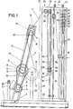
- Fig. 1 eine Ansicht der Vorrichtung,
- Fig. 2 eine klappfigürliche Ansicht der Fig. 1,
- Fig. 3 in größerer Darstellung den Zwischenspeicher,
- Fig. 4 den Schnitt nach der Linie IV-IV in Fig. 3,
- Fig. 5 den Schnitt nach der Linie V-V in Fig. 3 und
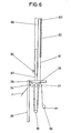
- Fig. 6 in schematisierter Darstellung eine abgewandelte Ausführungsform des Zwischenspeichers.
- 1 is a view of the device,
- FIG. 2 is a collapsible view of FIG. 1,
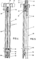
- 3 shows the buffer in a larger representation,
- 4 shows the section along the line IV-IV in FIG. 3,
- Fig. 5 shows the section along the line VV in Fig. 3 and
- Fig. 6 shows a schematic representation of a modified embodiment of the buffer.
Die Vorrichtung besitzt ein Fußgestell 1. Dieses lagert in seinem vorderen Abschnitt um eine horizontale Achse 2 einen Rahmen 3. Letzterer trägt in seinem unteren Bereich einen regelbaren Antriebsmotor 4 mit einer Riemenscheibe 5. Oberhalb des Antriebsmotors 4 sitzt auf einer von Lagern 6 des Rahmens 3 getragenen Welle 7 drehfest ein Reibrad 8. Das den Rahmen überragende Ende der horizontal ausgerichteten Welle 7 trägt eine Riemenscheibe 9. Um diese und um die Riemenscheibe 5 ist ein Riemen 10 gelegt. In unmittelbarer Nachbarschaft zur Riemenscheibe 9 befindet sich auf der Welle 7 eine weitere Riemenscheibe 11. Der um diese gelegte Riemen 12 versetzt eine Riemenscheibe 13 in Umdrehung, die ihrerseits auf eine Welle 14 aufgesteckt ist. Letztere ist im oberen Bereich des Rahmens 3 angeordnet und durchsetzt ein Lager 15 des Rahmens. Das rahmeneinwärts gerichtete Ende der Welle 14 nimmt eine Vergleichmäßigungstrommel 16 auf.The device has a base frame 1. This supports a
Das Reibrad 8 liegt auf der äußeren Fadenlage 17 einer Fadenspule 18 auf. Diese wird von Zentrierzapfen 19 getragen, die von vertikalen Säulen 20 des Fußgestells 1 ausgehen. Ist der Rahmen 3 in Richtung der Fadenspule 18 geschwenkt, so überschreitet er die lotrechte Lage und liegt zufolge Schwerkraft mit dem Reibrad 8 an der äußeren Fadenlage 17 an. Außer Eingriff kann das Reibrad 8 dadurch gebracht werden, daß der Rahmen 3 in entgegengesetzte Richtung verschwenkt wird. Ein vertikal stehender Ausleger 21 des Fußgestells dient dann mit einer Rolle 22 als Begrenzungsanschlag für den Rahmen 3. Diese Stellung eignet sich für das Einsetzen bzw. Auswechseln der Fadenspule 18.The
Der von der Fadenspule 18 abgewickelte Faden F durchläuft eine der Vergleichmäßigungstrommel 16 vorgeordnete, am Rahmen 3 befestigte Fadenöse 23. Von dort kommend, umschlingt er die Vergleichmäßigungstrommel 16 mehrfach derart, daß die auf diese aufgebrachten Fadenwindungen schlupffrei zur Vergteichmäßigungstrommet liegen. Von der Vergleichmäßigungstrommel 16 wird der Faden F in tangentialer Richtung abgezogen und durchläuft hierbei eine Fadenöse 24 des Rahmens 3. Danach gelangt der Faden F zu einem Faden-Zwischenspeicher 25.The thread F unwound from the
Im einzelnen besitzt der Faden-Zwischenspeicher den vom Fußgestell 1 ausgehenden Rahmenaufbau 26. Ein oberer Quersteg 27 desselben trägt einen nach rückwärts gerichteten, horizontal verlaufenden mittleren Ausleger 28. Diesem liegt ein unmittelbar am Fußgestell 1 befestigter horizontaler Ausleger 29 gegenüber. Die Ausleger 28, 29 tragen zwischen sich vertikale Schienen 30, 31, welche paarweise angeordnet sind. Zwischen den freien rückwärtigen Enden der Ausleger 28, 29 sind parallel zueinander angeordnete Stützen 32 vorgesehen, die zwischen sich Führungsstangen 33 aufnehmen.In detail, the thread buffer has the
Der Zwischenspeicher 25 enthält am oberen Ausleger 28 ortsfest gelagerte Fadenumlenkrollen 34 und 35. Ferner weist er die auf den vertikalen Schienen 30, 31 geführten, flaschenzugähnlich zueinander bewegbaren Fadenumlenkrollen 36, 37 auf. Die untere Fadenumlenkrolle 36 ist dabei als Mehrfachrolle ausgebildet, indem sie sich aus zwei Einzelrollen 36' und 36" zusammensetzt. Getragen werden die Einzelrollen 36', 36" von einem auf den Schienen 30 verschiebbaren Gleitschuh 38. Letzterer kann an seiner Oberseite Zusatzgewichte 39 aufnehmen. Der die Vergleichmäßigungstrommel 16 verlassende Faden F umschlingt vorerst die Umlenkrolle 34. Von dort gelangt er zur Einzelrolle 36', von wo er zur Umlenkrolle 35 verläuft und diese umschlingt. Fig. 4 veranschaulicht, daß die Umlenkrollen 34, 35 auf zwei benachbarten Ebenen zueinander liegen entsprechend dem Abstand der Einzelrollen 36' und 36" voneinander. Nach Umschlingen der Umlenkrolle 35 gelangt der Faden zur Einzelrolle 36" der Umlenkrolle 36, von wo aus er zur Fadenumlenkrolle 37 geführt wird. Letztere lagert in einem Gleitschuh 40, welcher auf den Schienen 31 verlagerbar angeordnet ist. An dem oberen Ende des Gleitschuhs 40 greift ein von Rollen 41, 42 umgelenkter Seilzug 43 an. Das freie Ende 43' dieses Seilzuges 43 verläuft zwischen den Führungsstangen 33 und trägt dort ein von den Führungsstangen 33 durchsetztes Einzelgewicht 44. Bei nicht arbeitender Vorrichtung liegt die Lage des Seilzuges gemäß Fig. 3 vor. Oberhalb des Gewichts 44 erstrecken sich weitere auf den Führungsstangen 33 gleitbare Einzelgewichte 45, 46, 47, 48 und 49, deren sich zwischen den Stützen 32 erstreckende Stege nach oben hin in ihrer Länge zunehmen. Diese Einzelgewichte 45 bis 49 liegen dabei auf an den Stützen 32 in gleichmäßigem Abstand angebrachten, einander zugekehrten Stützzapfen 50, 51, 52, 53, 54 auf, deren Länge nach oben hin abnimmt. Demgemäß können bei am Seilzug 43 auftretenden Zug verbunden mit einer Aufwärtsverlagerung des Gewichtes 44 sich die Einzelgewichte addieren entsprechend der Verlagerung des Seilzuges 43.The
Der von der Umlenkrolle 37 kommende Faden F umschlingt eine Umlenkrolle 55, die an der einen Stütze 32 befestigt ist. Von dort verläßt der Faden die Vorrichtung über eine Fadenöse 56.The thread F coming from the deflecting
Bei ruckartigem Fadenabzug werden sowohl die die abgezogene Fadenlänge straffende Umlenkrolle 36, bestehend aus den beiden Einzelrollen 36' und 36", und die entgegengesetzt dazu liegende Fadenumlenkrolle 37 verlagert unter Dämpfung der Spannungszunahme. Bei einer Verlagerung der oberen Umlenkrolle 37 addieren sich entsprechend dem Verlagerungsausmaß die Einzelgewichte, wie in Fig. 1 veranschaulicht ist. Im Bewegungsweg der die abgewickelte Fadenlänge straffenden Umlenkrolle 36 sind jedoch durch Pfeile angedeutete Abtasteinrichtungen 57, 58, 59, 60 vorgesehen, die die Reibrad-Antriebsgeschwindigkeit steuern. Gelangt z. B. die Umlenkrolle 36 in den Bereich der Abtasteinrichtung 60, so bedeutet dieses, daß eine größere Fadenlänge benötigt wurde und daß demzufolge der Reibrad-Antrieb mit größerer Geschwindigkeit arbeitet, um ausreichend Fadenlänge nachzuliefern.In the case of jerky thread take-off, both the
Bei der in Fig. 6 abgewandelten Ausführungsform wird die Fadenumlenkrolle 37 nicht von sich addierenden Einzelgewichten belastet. An der Fadenumlenkrolle 37 greift nun ein Seilzug 61 an, der mit dem einen Ende einer Zugfeder 62 verbunden ist. Dessen anderes Ende 62" geht von einem Teleskopschuh 65 aus. Dieser führt sich auf einer den oberen Ausleger 28 überragenden vertikalen Säule 63 und ist mittels der Klemmschraube 64 einstellbar, um unterschiedliche Belastungen auf die Umlenkrolle 37 ausüben zu können. Durch die Länge des Seiles 61 ist die Bewegungsmöglichkeit der Fadenumlenkrolle 37 begrenzt, und das Nachwippen der Zugfeder bei Erreichen der Normalstellung dieser Fadenumlenkrolle 37 wird vermieden. Gegebenenfalls ist es auch möglich, die Zugfeder 62 und den Teleskopschuh 65 in horizontaler Ausrichtung anzubringen.In the embodiment modified in FIG. 6, the
Alle in der Beschreibung erwähnten und in der Zeichnung dargestellten neuen Merkmale sind erfindungswesentlich, auch soweit sie in den Ansprüchen nicht ausdrücklich beansprucht sind.All the new features mentioned in the description and shown in the drawing are essential to the invention, even if they are not expressly claimed in the claims.
Claims (9)
Applications Claiming Priority (2)
| Application Number | Priority Date | Filing Date | Title |
|---|---|---|---|
| DE3216605 | 1982-05-04 | ||
| DE3216605 | 1982-05-04 |
Publications (2)
| Publication Number | Publication Date |
|---|---|
| EP0093226A2 true EP0093226A2 (en) | 1983-11-09 |
| EP0093226A3 EP0093226A3 (en) | 1985-09-18 |
Family
ID=6162645
Family Applications (1)
| Application Number | Title | Priority Date | Filing Date |
|---|---|---|---|
| EP83100732A Withdrawn EP0093226A3 (en) | 1982-05-04 | 1983-01-27 | Filamentary material feeding apparatus, especially for wire, by withdrawing it from a reel |
Country Status (1)
| Country | Link |
|---|---|
| EP (1) | EP0093226A3 (en) |
Cited By (3)
| Publication number | Priority date | Publication date | Assignee | Title |
|---|---|---|---|---|
| EP0287802A2 (en) * | 1987-04-23 | 1988-10-26 | STATOMAT-GLOBE Machinenfabrik GmbH | Device for feeding cable from a supply reel to a cable fabrication machine |
| DE102005015528A1 (en) * | 2005-04-04 | 2006-10-05 | Josef Soller | Machine for fixing vertical wires to horizontal tensioned wires in hop fields has pulley system which temporarily stores wire fed from reel during fixing |
| CN102295188A (en) * | 2011-05-27 | 2011-12-28 | 常州市第八纺织机械有限公司 | Yarn storage mechanism for composite material production line |
Citations (12)
| Publication number | Priority date | Publication date | Assignee | Title |
|---|---|---|---|---|
| DE449957C (en) * | 1925-02-04 | 1927-10-03 | Carl Christian Erdmann | Spooling device, especially for very fine wires and threads, with automatic activation of a drive device for the pay-off spool |
| US2141934A (en) * | 1936-04-18 | 1938-12-27 | Waterbury Farrel Foundry & Mac | Belt driven wire spooler |
| US2560204A (en) * | 1947-06-17 | 1951-07-10 | Artos Engineering Co | Automatic strand feed regulator |
| US2594427A (en) * | 1947-05-22 | 1952-04-29 | Western Electric Co | Method and apparatus for uniformly tensioning an advancing strand |
| US2929569A (en) * | 1957-02-26 | 1960-03-22 | Western Electric Co | Continuous wire winding apparatus |
| US2996263A (en) * | 1957-07-01 | 1961-08-15 | B B Chem Co | Winding machine |
| US3022812A (en) * | 1957-02-21 | 1962-02-27 | Alvin F Groll | Feed control means |
| FR1358595A (en) * | 1963-03-07 | 1964-04-17 | Geoffroy Delore | Donor start coil stranding machine with receiving drum slip |
| US3289959A (en) * | 1966-12-06 | Material feed control device | ||
| US3334838A (en) * | 1964-09-05 | 1967-08-08 | Kopp & Odenwald | Apparatus for feeding wound material to a processing machine |
| US3501075A (en) * | 1967-11-28 | 1970-03-17 | Herbert D Scharf | Wire tension control device |
| FR2154205A7 (en) * | 1971-09-23 | 1973-05-04 | Rieter Ag Maschf |
-
1983
- 1983-01-27 EP EP83100732A patent/EP0093226A3/en not_active Withdrawn
Patent Citations (12)
| Publication number | Priority date | Publication date | Assignee | Title |
|---|---|---|---|---|
| US3289959A (en) * | 1966-12-06 | Material feed control device | ||
| DE449957C (en) * | 1925-02-04 | 1927-10-03 | Carl Christian Erdmann | Spooling device, especially for very fine wires and threads, with automatic activation of a drive device for the pay-off spool |
| US2141934A (en) * | 1936-04-18 | 1938-12-27 | Waterbury Farrel Foundry & Mac | Belt driven wire spooler |
| US2594427A (en) * | 1947-05-22 | 1952-04-29 | Western Electric Co | Method and apparatus for uniformly tensioning an advancing strand |
| US2560204A (en) * | 1947-06-17 | 1951-07-10 | Artos Engineering Co | Automatic strand feed regulator |
| US3022812A (en) * | 1957-02-21 | 1962-02-27 | Alvin F Groll | Feed control means |
| US2929569A (en) * | 1957-02-26 | 1960-03-22 | Western Electric Co | Continuous wire winding apparatus |
| US2996263A (en) * | 1957-07-01 | 1961-08-15 | B B Chem Co | Winding machine |
| FR1358595A (en) * | 1963-03-07 | 1964-04-17 | Geoffroy Delore | Donor start coil stranding machine with receiving drum slip |
| US3334838A (en) * | 1964-09-05 | 1967-08-08 | Kopp & Odenwald | Apparatus for feeding wound material to a processing machine |
| US3501075A (en) * | 1967-11-28 | 1970-03-17 | Herbert D Scharf | Wire tension control device |
| FR2154205A7 (en) * | 1971-09-23 | 1973-05-04 | Rieter Ag Maschf |
Cited By (6)
| Publication number | Priority date | Publication date | Assignee | Title |
|---|---|---|---|---|
| EP0287802A2 (en) * | 1987-04-23 | 1988-10-26 | STATOMAT-GLOBE Machinenfabrik GmbH | Device for feeding cable from a supply reel to a cable fabrication machine |
| EP0287802A3 (en) * | 1987-04-23 | 1990-08-01 | STATOMAT-GLOBE Machinenfabrik GmbH | Device for feeding cable from a supply reel to a cable fabrication machine |
| DE102005015528A1 (en) * | 2005-04-04 | 2006-10-05 | Josef Soller | Machine for fixing vertical wires to horizontal tensioned wires in hop fields has pulley system which temporarily stores wire fed from reel during fixing |
| DE102005015528A9 (en) * | 2005-04-04 | 2007-02-01 | Josef Soller | Device, in particular for attaching ascending wires to the tension wire in hop gardens |
| CN102295188A (en) * | 2011-05-27 | 2011-12-28 | 常州市第八纺织机械有限公司 | Yarn storage mechanism for composite material production line |
| CN102295188B (en) * | 2011-05-27 | 2013-07-10 | 常州市第八纺织机械有限公司 | Yarn storage mechanism for composite material production line |
Also Published As
| Publication number | Publication date |
|---|---|
| EP0093226A3 (en) | 1985-09-18 |
Similar Documents
| Publication | Publication Date | Title |
|---|---|---|
| DE4324412C2 (en) | Device for adjusting the thread tension | |
| DE3233869C2 (en) | Device for supplying elastomeric threads, in particular for knitting and warp-knitting machines | |
| CH694370A5 (en) | Winder. | |
| WO2018108989A1 (en) | Friction feeder | |
| DE2132416A1 (en) | Device for the continuous production of reinforcements | |
| DE2605566A1 (en) | YARN FEEDING DEVICE FOR MILLING MACHINES | |
| DE1785336B2 (en) | Device for winding chemical threads | |
| DE2650590C2 (en) | Method and device for producing a braided roll | |
| EP0093226A2 (en) | Filamentary material feeding apparatus, especially for wire, by withdrawing it from a reel | |
| DE3046003A1 (en) | AUTOMATIC YARN FEEDING FOR ROUND KNITTING OR KNITTING MACHINES | |
| CH638159A5 (en) | DEVICE FOR REMOVING, STORING AND DEPOSITING ENDLESS FILAMENT, STRAND OR CABLE MATERIAL. | |
| DE3819885A1 (en) | Winding apparatus | |
| DE2635200C2 (en) | Thread feeder | |
| DE2550612C3 (en) | Winding machine | |
| DE3916363C2 (en) | ||
| DE2538819C3 (en) | Winding machine for producing a helical row of zipper links from a plastic wire | |
| WO1999041180A1 (en) | Winding device | |
| DE2727813C2 (en) | Device for unwinding welding wire | |
| CH382617A (en) | Device to keep the tension of the wound material constant with variable take-off speed for winding and winding machines | |
| DE1221937B (en) | Compensating device for the thread withdrawal from several freely rotatable bobbins, especially in two-for-one twisting machines | |
| DE3817679C1 (en) | Cabling machine | |
| DE19635373C2 (en) | Device for compensating for thread consumption and thread tension fluctuations when feeding thread-like material | |
| CH386201A (en) | Method and apparatus for drawing yarn from packages of yarn | |
| DE2402055A1 (en) | Sewing machine tape and thread supply unit - with common support carrying thread bobbins, tape reels and tape feed system | |
| CH620720A5 (en) |
Legal Events
| Date | Code | Title | Description |
|---|---|---|---|
| PUAI | Public reference made under article 153(3) epc to a published international application that has entered the european phase |
Free format text: ORIGINAL CODE: 0009012 |
|
| AK | Designated contracting states |
Designated state(s): AT BE CH DE FR GB IT LI LU NL SE |
|
| PUAL | Search report despatched |
Free format text: ORIGINAL CODE: 0009013 |
|
| AK | Designated contracting states |
Designated state(s): AT BE CH DE FR GB IT LI LU NL SE |
|
| STAA | Information on the status of an ep patent application or granted ep patent |
Free format text: STATUS: THE APPLICATION IS DEEMED TO BE WITHDRAWN |
|
| 18D | Application deemed to be withdrawn |
Effective date: 19850801 |