EP0092970A2 - Vorrichtung zum Herstellen und Abgeben von ungefüllten Schlauchhüllen an einem Sammelplatz - Google Patents
Vorrichtung zum Herstellen und Abgeben von ungefüllten Schlauchhüllen an einem Sammelplatz Download PDFInfo
- Publication number
- EP0092970A2 EP0092970A2 EP83302241A EP83302241A EP0092970A2 EP 0092970 A2 EP0092970 A2 EP 0092970A2 EP 83302241 A EP83302241 A EP 83302241A EP 83302241 A EP83302241 A EP 83302241A EP 0092970 A2 EP0092970 A2 EP 0092970A2
- Authority
- EP
- European Patent Office
- Prior art keywords
- knotting
- tubular
- station
- storage station
- knotted loop
- Prior art date
- Legal status (The legal status is an assumption and is not a legal conclusion. Google has not performed a legal analysis and makes no representation as to the accuracy of the status listed.)
- Granted
Links
Images


Classifications
-
- A—HUMAN NECESSITIES
- A22—BUTCHERING; MEAT TREATMENT; PROCESSING POULTRY OR FISH
- A22C—PROCESSING MEAT, POULTRY, OR FISH
- A22C11/00—Sausage making ; Apparatus for handling or conveying sausage products during manufacture
- A22C11/12—Apparatus for tying sausage skins ; Clipping sausage skins
-
- A—HUMAN NECESSITIES
- A22—BUTCHERING; MEAT TREATMENT; PROCESSING POULTRY OR FISH
- A22C—PROCESSING MEAT, POULTRY, OR FISH
- A22C11/00—Sausage making ; Apparatus for handling or conveying sausage products during manufacture
-
- A—HUMAN NECESSITIES
- A22—BUTCHERING; MEAT TREATMENT; PROCESSING POULTRY OR FISH
- A22C—PROCESSING MEAT, POULTRY, OR FISH
- A22C13/00—Sausage casings
Definitions
- This invention relates to apparatus for forming and delivering unfilled tubular casings to a storage station at which they are suspended , the casings being formed from a web of tubular film around which a knotted loop is taken to form a closed end of the casing and the tubular film then being cut to form a predetermined length of tubular casing attached to the knotted loop.
- Apparatus according to the invention represents improvements in known equipment for knotting automatically the openings of flexible containers by making a knot which forms an end which is used to hang the flexible container, such as for example a sausage skin, which is derived from a reel supply of folded tubular skin, and to equipment which cuts the skin immediately after the opening of the next succeeding flexible container has been knotted by the equipment.
- Spanish Patent No.475,086 European Patent Publication No.0010937
- a method and device for knotting openings of flexible containers automatically A knotted loop is formed around a flexible container from cord which is applied in loops along one side of a paper laminate.
- the method and apparatus disclosed provide a significant advance in the automatic knotting of sausage skins, particularly over the equipment disclosed in the Spanish Patent No.295,446 (U.K.Patent Specification No.1,077,784) also in the name of the Applicant, and also over any other known methods of knotting sausage skins.
- the present invention has been developed primarily with a view to providing apparatus which can operate automatically to form and deliver unfilled tubular casings in such a way that an operator in charge of the apparatus only has to attend to the routine control over three matters , namely (a) a proper supply of tubular film (from which the casings are formed) to the apparatus; (b) maintain a supply of cord or other knotted loop-forming material; and (c) to unload, when necessary, tubular casings each suspended, at one end, by respective knotted loops in a store provided in the apparatus.
- apparatus for forming and delivering unfilled tubular casings to a storage station at which they are suspended, the apparatus comprising means for supplying a web of tubular film, a knotting and cutting station having a knotting device arranged to apply a knotted loop around the tubular film to form a closed end of a tubular casing and a cutting device arranged to cut the tubular film and thereby form a predetermined length of tubular casing attached to the knotted loop, and means for conveying the tubular casing to the storage station to be suspended by its knotted loop at the station, the apparatus being characterised by:
- a device is provided upstream of the knotting and cutting station in order to form the web of tubular film with multiple longitudinal pleats .
- This known pleating has usually been carried out in one of two ways.
- a pair of toothed wheels are used, through which the sausage skin is made to pass'cross-wise.
- the toothed wheel system presents the most serious disadvantages of having the teeth of the wheels adversely affecting the skin to such an extent that they may even penetrate it, and also of having to introduce the skins sideways one by one, thus preventing a continuous feeding of the skin.
- the disadvantages of the known means for forming pleating in a tubular casing are overcome, by provision of a device which operates automatically in the apparatus of the invention.
- tubular casings are formed from a web supply of tubular film around which a knotted loop is applied to form a closed end of the tubular casing.
- the tubular film is then cut to form a predetermined length of tubular casing attached to the knotted loop , which is then conveyed to a storage station at which the casings are suspended.
- a knotting and cutting station having a knotting device arranged to apply the knotted loop around the tubular film , and also a cutting device which cuts the tubular film after the knotted loop has been drawn towards the storage station , whereby a predetermined length of tubular casing is drawn out also and is then cut by the cutting device.
- the knotting and cutting device are not shown in detail herein, but conveniently may take the form of the knotting device and cutting device arrangement described and illustrated in more detail in European Patent Publication No.0010937 (Application No.79302354.0) of the Applicant , to which reference is directed.
- the means for forming the knotted loop around the tubular film, and the means for cutting the tubular casing to length are not major elements of the invention, and any suitable means may be provided, as desired.
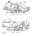
- FIG 1 Part of the apparatus is illustrated in Figure 1, and comprises an engaging device for engaging a knotted loop formed at one end of a tubular casing, the engaging device being designated generally by reference numeral 3, and comprising a hook 6 at one end and an actuator lever 9 at an opposite end, all of which are carried by a movable support 4.
- the engaging device is movable automatically back and forth between a knotting and cutting station and a storage station provided by the apparatus.
- the knotting and cutting station is shown more clearly in Figure 3, at which it will be seen that a knotted loop 1 has been applied around one end of a tubular casing 2.
- the means for forming the knotted loop is not shown in detail herein, though it is shown schematically in dash-dot lines in Figure 3, somewhat similar to the knotted loop forming means disclosed in European Patent Publication referred to above.
- the storage station is shown in more detail in Figure 6, at which is provided one or more storage devices 15 on which a stack of unfilled tubular casings can be hung via their respective knotted loops 1.
- the movable support 4 is caused to reciprocate between the two stations by means of an operating cylinder 5, and movement towards the knotting and cutting stations, as shown in Figure 3, enables the hook 6 to engage knotted loop 1. Subsequent return of the support 4 to the storage station causes the knotted loop 1 to be drawn towards the storage station, thereby also drawing an attached length of tubular film which will form the tubular casing' 2 - upon subsequent cutting of the tubular film at the knotting and cutting station.
- the engaging device 3 takes the form of a shuttle, to the leading end of which the hook 6 is attached.
- the hook 6 is capable of limited longitudinal movement relative to the shuttle 3, and a spring 7 tends to draw the hook 6 in a direction towards the support 4.
- an actuator lever 9 is pivotally connected to the rear end 8 of the hook 6, and is pivotally mounted on the support 4 by means of a pivot 10 (see Figure 4).
- the actuator lever 9 comprises an angle lever which is pivotal between an operative position, shown in Figures 4 and 5 , and and inoperative position shown in Figures 1,3 and 8.
- the actuator lever 9 adopts the operative position when the hook 6 has come into engagement with a properly formed knotted loop 1 at the end of tubular casing 2. With the actuator lever 9 in the operative position, return movement of the shuttle 3 to the storage station causes the actuator lever 9 to operate control means which controls the cycle of operation of the apparatus.
- the actuator lever 9 remains in its inoperative position during the return movement to the storage station, and the actuator lever then does not operate on the control means to initiate a further cycle of operation.
- the actuator lever 9 includes an actuator arm 11 which extends horizontally in the inoperative position of the actuator lever 9 , and extends in a downwardly inclined position, as shown in Figures 4 and 5, in the operative position.
- the shuttle 3 occupies an initial idling position in which it is located at its most distant position from the knotting point (knotting and cutting station).
- the shuttle 3 is then advanced by the operating cylinder 5 towards the knotting point , as shown in Figure 3, passes through the knotted loop 1 and then commences the return movement to the storage station , as shown in Figure 4, engaging with the loop 1 and drawing a portion of the tubular film away from the knotting point towards the storage station. until the initial position is again reached, as shown in Figure 5.
- the operating cylinder 5 is connected by a piston rod 16 to the support 4, and end stops 13 and 17 define the limits to the reciprocating movement in each direction of the support 4.
- actuator arm 11 operates actuator 12 which causes limit stop 13 to operate a drive push button 14 which controls the operation of the knotting and cutting devices (not shown) at the knotting and cutting station.
- the advance movement of the shuttle 3 from the storage station is initiated under the action of operating cylinder 5.
- limit stop 17 is operated by the movable support 4 , which reverses the direction of movement of the support 4 under the action of rod 16 operated by cylinder 5.
- the actuator 12 , limit stop 13, and push button 14 comprise, in combination with a control arrangement designated generally by reference numeral 28, control means which controls the cycle of operational movement of the shuttle 3 , and also of the knotting and cutting devices provided at the knotting point.
- a screw 18 is provided which adjustably connects the drive control arrangement 28 to a protective tubular casing 26 by being taken through a longitudinal slot 27 formed in casing 26.
- screw 18 connects a support bar 19 of the storage devices 15 so that these also can be adjusted along the length of the tubular casing 26. Movement of the screw or bolt 18 along slot 27 will cause adjustment of the distance between the two stations of the apparatus, and thereby adjust the cut length of each tubular casing 2.
- the support bar 19 has been cut away, in the illustrations of Figures 1,5,6 and 8.
- two hook shaped storage devices 15 are provided so that, when one of them is fully loaded with casings 2, it can be pivoted on its support until the remaining device 15 which is empty can take up a position ready to receive a further succession of knotted loops 1. Accordingly, it is not necessary to stop the operation of the apparatus to remove the casings 2, until both of the storage devices are fully loaded. If desired, further storage devices 15 may be provided at the storage station.
- the wheel 22 is provided on the free end of the rods 20, and engages the ramp 23 so as to pivot the rods 20 upwardly about pivot 21. This is the situation as shown in Figure 5. However, when the wheel 22 no longer engages the ramp 23, which coincides with the moment when the hook 6 becomes unfastened from the knotted loop 1 (see Figure 6) , the rods 20 return to their original idle position under the action of torsion spring 29 and thereby push the knotted loop 1 downwards onto the upper end of the hook shaped storage device 15.
- the hook shape storage devices 15 , and the push rods 20, form a unit which is capable of being altered in position, in that the unit is suspended by a bracket 24 from a guide bar 25 along which the bracket 24 can be adjusted.
- FIG. 9 there is illustrated a device which is arranged upstream of the knotting and cutting station, and serves to apply multiple longitudinal folds to a web 32 of flattened tubular film from which the tubular casings 2 are formed.
- the folding device comprises an upper plate 30 and a lower plate 31 which are hinged together , with the upper plate 30 being movable to an open position shown in Figure 9 in order to allow initial placement of the web 32.
- the web 32 is taken from a reel supply, and is taken through an entry end 33 of the plates 30 and 31, and then leaves via an exit 34.
- the plate 30 is hinged downwardly to a position parallel, but closely spaced above the plate 31, and folding and guiding elements provided between the plates 30 and 31 serve to apply multiple longitudinal folds to the web 32.
- the web 32 is flat when it passes through entry end 33, but has multiple longitudinal folds as it leaves exit 34.
- a progressively narrowing guide path is provided for the web 32 by means of pairs of lateral limiting elements 35 which extend upwardly from plate 31 and have tapered upper ends 39 taken through holes 40 formed in the upper plate 30.
- the pairs of elements 35 are spaced apart by distances which narrow from the entry end 33 to the exit end 34 of the plates 30 and 31.
- the elements 35 comprise rollers which are rotatable about axes extending perpendicular to the plane of the plates 30 and 31.
- transversely extending folding elements are arranged within the space defined between the plates 30 and 31, transversely extending folding elements are arranged , upper folding elements 36 being rotatably mounted in the plate 30, and lower elements 37 being rotatably mounted in plate 31.
- the folding elements 36 and 37 extend transversely between the lateral elements35 and transversely of the path of movement of the web 32.through the plates 30 and 31.
- the laterally outer ends 38 of the folding elements 36 and 37 are separated from the adjacent elements 35 by a distance which is less than or equal to the distance which separates the plates 30 and 31.
- the lateral limiting elements 35 comprise freely rotatable rollers having conically tapering upper ends 39 rotatable in the holes 40.
- the transversely extending folding elements (36,37) of at least one of the plates 30 and 31 , and in the illustrated embodiment; the folding elements 37 of the plate 31 , are advantageously made of freely rotatable rollers having an axis of rotation extending parallel to the plates 30 and 31.
- the transversely extending folding elements 36 and 37 are slightly tapered at their ends.
Landscapes
- Life Sciences & Earth Sciences (AREA)
- Engineering & Computer Science (AREA)
- Wood Science & Technology (AREA)
- Zoology (AREA)
- Food Science & Technology (AREA)
- Containers And Plastic Fillers For Packaging (AREA)
- Making Paper Articles (AREA)
- Folding Of Thin Sheet-Like Materials, Special Discharging Devices, And Others (AREA)
- Treatment Of Fiber Materials (AREA)
Applications Claiming Priority (4)
| Application Number | Priority Date | Filing Date | Title |
|---|---|---|---|
| ES512263A ES512263A0 (es) | 1982-04-23 | 1982-04-23 | "perfeccionamientos en aparatos para anudar automaticamente bocas de envases flexibles". |
| ES1982265171U ES265171Y (es) | 1982-04-23 | 1982-04-23 | "dispositivo para formar multiples pliegues longitudinales en tiras substancialmente laminables". |
| ES512263 | 1982-04-23 | ||
| ES265171U | 1982-04-23 |
Related Child Applications (2)
| Application Number | Title | Priority Date | Filing Date |
|---|---|---|---|
| EP88113498A Division EP0305825A3 (de) | 1982-04-23 | 1983-04-20 | Vorrichtung zum Plissieren von ungefüllten Schlauchhüllen |
| EP88113498.5 Division-Into | 1988-08-19 |
Publications (3)
| Publication Number | Publication Date |
|---|---|
| EP0092970A2 true EP0092970A2 (de) | 1983-11-02 |
| EP0092970A3 EP0092970A3 (en) | 1986-04-02 |
| EP0092970B1 EP0092970B1 (de) | 1990-02-28 |
Family
ID=26155511
Family Applications (2)
| Application Number | Title | Priority Date | Filing Date |
|---|---|---|---|
| EP88113498A Withdrawn EP0305825A3 (de) | 1982-04-23 | 1983-04-20 | Vorrichtung zum Plissieren von ungefüllten Schlauchhüllen |
| EP83302241A Expired - Lifetime EP0092970B1 (de) | 1982-04-23 | 1983-04-20 | Vorrichtung zum Herstellen und Abgeben von ungefüllten Schlauchhüllen an einem Sammelplatz |
Family Applications Before (1)
| Application Number | Title | Priority Date | Filing Date |
|---|---|---|---|
| EP88113498A Withdrawn EP0305825A3 (de) | 1982-04-23 | 1983-04-20 | Vorrichtung zum Plissieren von ungefüllten Schlauchhüllen |
Country Status (6)
| Country | Link |
|---|---|
| US (2) | US4533164A (de) |
| EP (2) | EP0305825A3 (de) |
| AR (1) | AR230926A1 (de) |
| CA (1) | CA1226251A (de) |
| DE (1) | DE3381232D1 (de) |
| DK (1) | DK174583A (de) |
Cited By (2)
| Publication number | Priority date | Publication date | Assignee | Title |
|---|---|---|---|---|
| FR2619285A1 (fr) * | 1987-08-10 | 1989-02-17 | Freres & Cie Charles | Installation et procede permettant de saisir des produits de charcuterie par leur ligaturage apres nouage, et de les positionner sur des barres de presentation et de sechage |
| EP0666029A1 (de) * | 1994-02-02 | 1995-08-09 | Hoechst Aktiengesellschaft | Vorrichtung zum Zählen, Sammeln und Transportieren von Wursthüllen sowie Verfahren |
Families Citing this family (3)
| Publication number | Priority date | Publication date | Assignee | Title |
|---|---|---|---|---|
| GB2180714B (en) * | 1985-08-22 | 1989-08-16 | Rank Xerox Ltd | Image apparatus |
| FR2589045B1 (fr) * | 1985-10-24 | 1988-01-22 | Freres & Cie Charles | Perfectionnements aux machines automatiques permettant de ligaturer au moyen d'un fil, ficelle ou analogues, des produits du type saucisses, saucissons et similaires |
| US5755022A (en) * | 1995-11-14 | 1998-05-26 | Delaware Capital Formation, Inc. | Mechanism for feeding a string loop into a clip attachment apparatus |
Family Cites Families (20)
| Publication number | Priority date | Publication date | Assignee | Title |
|---|---|---|---|---|
| US654515A (en) * | 1899-09-19 | 1900-07-24 | Edwin Dake Casterline | Paper-folding machine. |
| US1537118A (en) * | 1924-06-14 | 1925-05-12 | Kent Charlotte Elizabeth | Cloth-folding device |
| DE564187C (de) * | 1931-04-24 | 1932-11-18 | Ernst Brocker | Maschine zum Abschneiden und Abbinden von Wurstdaermen |
| US2070568A (en) * | 1933-08-15 | 1937-02-16 | American Can Co | Stacking device |
| US2322447A (en) * | 1938-06-25 | 1943-06-22 | Henry A Hensel | Tied sausage casing and method for tying |
| GB518606A (en) * | 1938-10-29 | 1940-03-01 | Knorr Naehrmittel Ag | Improved method of and means for tying knots |
| GB649847A (en) * | 1947-07-17 | 1951-02-07 | Sven Emanuel Bengtson | Machine for preparing sausage casings for filling |
| US2498948A (en) * | 1947-08-02 | 1950-02-28 | Flomen Edward | Apparatus for shirring sausage casings |
| US2616572A (en) * | 1949-08-30 | 1952-11-04 | Swift & Co | Casing stick holder |
| CH438070A (de) * | 1964-01-17 | 1967-06-15 | Barroso Angel L | Verfahren für das mechanische Binden von Würsten |
| CH419190A (fr) * | 1964-02-06 | 1966-08-31 | Le Poittevin Andre | Procédé et dispositif pour le pliage des journaux |
| US3261268A (en) * | 1964-03-27 | 1966-07-19 | Rheem Mfg Co | Pleater for sheet material and means for tying and cutting casings |
| US3348458A (en) * | 1964-03-27 | 1967-10-24 | Rheem Mfg Co | Pleater for sheet material and means for tying and cutting casings |
| US3483801A (en) * | 1966-08-26 | 1969-12-16 | Union Carbide Corp | Casing closure apparatus and method |
| US3533495A (en) * | 1968-08-14 | 1970-10-13 | Schmidt Wallace Inc | Apparatus for handling wieners and the like |
| US3672001A (en) * | 1970-06-29 | 1972-06-27 | Townsend Engineering Co | Product encasing machine |
| US3940169A (en) * | 1974-10-22 | 1976-02-24 | The Procter & Gamble Company | Loop knot tying method and apparatus |
| ES475086A1 (es) * | 1978-10-31 | 1981-06-16 | Barroso Angel L | Metodo y aparato para anudar automaticamente bocas de enva- ses flexibles. |
| US4252591A (en) * | 1979-05-02 | 1981-02-24 | Pall Corporation | Corrugating apparatus and process |
| DE2950603A1 (de) * | 1979-12-15 | 1981-06-19 | Herbert Dipl.-Ing. 6240 Königstein Niedecker | Vorrichtung zur uebergabe von wurstaufhaengeschlaufen in eine verschleissmaschine |
-
1983
- 1983-04-20 EP EP88113498A patent/EP0305825A3/de not_active Withdrawn
- 1983-04-20 EP EP83302241A patent/EP0092970B1/de not_active Expired - Lifetime
- 1983-04-20 DE DE8383302241T patent/DE3381232D1/de not_active Expired - Lifetime
- 1983-04-21 DK DK174583A patent/DK174583A/da not_active Application Discontinuation
- 1983-04-21 AR AR292780A patent/AR230926A1/es active
- 1983-04-22 CA CA000426488A patent/CA1226251A/en not_active Expired
- 1983-04-22 US US06/487,766 patent/US4533164A/en not_active Expired - Fee Related
-
1985
- 1985-08-01 US US06/761,492 patent/US4621751A/en not_active Expired - Lifetime
Cited By (3)
| Publication number | Priority date | Publication date | Assignee | Title |
|---|---|---|---|---|
| FR2619285A1 (fr) * | 1987-08-10 | 1989-02-17 | Freres & Cie Charles | Installation et procede permettant de saisir des produits de charcuterie par leur ligaturage apres nouage, et de les positionner sur des barres de presentation et de sechage |
| EP0666029A1 (de) * | 1994-02-02 | 1995-08-09 | Hoechst Aktiengesellschaft | Vorrichtung zum Zählen, Sammeln und Transportieren von Wursthüllen sowie Verfahren |
| US5579892A (en) * | 1994-02-02 | 1996-12-03 | Hoechst Aktiengesellschaft | Apparatus for the counting, collection and transportation of sausage casings and process |
Also Published As
| Publication number | Publication date |
|---|---|
| CA1226251A (en) | 1987-09-01 |
| US4533164A (en) | 1985-08-06 |
| EP0305825A3 (de) | 1989-04-19 |
| US4621751A (en) | 1986-11-11 |
| EP0305825A2 (de) | 1989-03-08 |
| AR230926A1 (es) | 1984-08-31 |
| EP0092970B1 (de) | 1990-02-28 |
| DE3381232D1 (de) | 1990-04-05 |
| EP0092970A3 (en) | 1986-04-02 |
| DK174583D0 (da) | 1983-04-21 |
| DK174583A (da) | 1983-10-24 |
Similar Documents
| Publication | Publication Date | Title |
|---|---|---|
| EP0352825B1 (de) | Verpackungsvorrichtung für den Einsatz von schlauchförmigem Hüllmaterial | |
| EP0962143B1 (de) | Vorrichtung zum Herstellen von Würsten | |
| EP0587253B1 (de) | Verfahren und Vorrichtung zur Bearbeitung eines Organen-Pakets eines Schlachttieres | |
| DE69809969T2 (de) | Lineare hochgeschwindigkeitsbeutelfüllvorrichtung und betriebsverfahren | |
| AU704000B2 (en) | Mechanism for feeding a string loop into a clip attachment apparatus | |
| US4841851A (en) | Roll baling press for harvest product | |
| EP1891859B2 (de) | Übergabevorrichtung für an Halteschlaufen hängende Verpackungseinheiten | |
| EP0243906B1 (de) | Verfahren und Vorrichtung zum Herstellen von tragbaren, rohrförmigen Paketen aus Druckprodukten, wie Zeitungen, Zeitschriften und dergleichen | |
| EP0522110A1 (de) | Verfahren zur automatischen sackbereitstellung und sackanhängevorrichtung. | |
| US5041053A (en) | Heart harvesting system and method | |
| US4541660A (en) | Automatic machine for binding products in accordance with a pre-established sequence | |
| DE2541589A1 (de) | Vorrichtung zum selbsttaetigen anspinnen | |
| US20170081055A1 (en) | Vertically Positioned Horizontally Traversing Plastic Film Bags Opening, Filling and Closing Apparatus Including Vertically Moving Supporting Conveyor | |
| US20170080634A1 (en) | Aligned Perforation Knife and Heat Seal Bar Apparatus for Vertically Positioned Horizontally Traversing Plastic Film Bags Forming Machine | |
| DE102006017017A1 (de) | Direktanbindung von Wurstclip- und Wurstfördereinrichtung | |
| EP0092970A2 (de) | Vorrichtung zum Herstellen und Abgeben von ungefüllten Schlauchhüllen an einem Sammelplatz | |
| US20170081062A1 (en) | Apparatus for Pulling Vertically Positioned Horizontally Traversing Plastic Film Bag Walls and Heat Fusing the Walls and Closing the Bag | |
| EP1201539B1 (de) | Vorrichtung zum Herstellen und vorzugsweise auch zum Befüllen und Verschliessen von Säcken aus thermoplastichem Kunststoff | |
| EP1205110B1 (de) | Längeneinheit mit Clipmodul | |
| US3469367A (en) | Bag feeding and filling apparatus | |
| EP1874122B1 (de) | Vorrichtung zum befüllen von verpackungshüllen mit einem füllgut | |
| NL8204097A (nl) | Werkwijze en middelen voor het aan draagbanden rijgen van gespen. | |
| US3140026A (en) | Strip severing machine | |
| EP4437853B1 (de) | System und verfahren zum zuführen von flexiblen aufhängungselementen zu einem wurstförmigen produkt | |
| DE10111136B4 (de) | Verfahren, Endlos-Rollenware für das Verfahren und Vorrichtung zum Abtrennen von Schlauchabschnitten von einer flachgelegten schlauchförmigen Endlos-Rollenware |
Legal Events
| Date | Code | Title | Description |
|---|---|---|---|
| PUAI | Public reference made under article 153(3) epc to a published international application that has entered the european phase |
Free format text: ORIGINAL CODE: 0009012 |
|
| AK | Designated contracting states |
Designated state(s): BE DE FR GB IT LU NL SE |
|
| RHK1 | Main classification (correction) |
Ipc: A22C 13/00 |
|
| PUAL | Search report despatched |
Free format text: ORIGINAL CODE: 0009013 |
|
| AK | Designated contracting states |
Kind code of ref document: A3 Designated state(s): BE DE FR GB IT LU NL SE |
|
| 17P | Request for examination filed |
Effective date: 19860818 |
|
| 17Q | First examination report despatched |
Effective date: 19871130 |
|
| GRAA | (expected) grant |
Free format text: ORIGINAL CODE: 0009210 |
|
| AK | Designated contracting states |
Kind code of ref document: B1 Designated state(s): BE DE FR GB IT LU NL SE |
|
| PG25 | Lapsed in a contracting state [announced via postgrant information from national office to epo] |
Ref country code: SE Effective date: 19900228 Ref country code: NL Effective date: 19900228 Ref country code: FR Effective date: 19900228 Ref country code: BE Effective date: 19900228 |
|
| REF | Corresponds to: |
Ref document number: 3381232 Country of ref document: DE Date of ref document: 19900405 |
|
| PG25 | Lapsed in a contracting state [announced via postgrant information from national office to epo] |
Ref country code: GB Effective date: 19900428 |
|
| PG25 | Lapsed in a contracting state [announced via postgrant information from national office to epo] |
Ref country code: LU Free format text: LAPSE BECAUSE OF NON-PAYMENT OF DUE FEES Effective date: 19900430 |
|
| ITF | It: translation for a ep patent filed | ||
| EN | Fr: translation not filed | ||
| NLV1 | Nl: lapsed or annulled due to failure to fulfill the requirements of art. 29p and 29m of the patents act | ||
| PLBE | No opposition filed within time limit |
Free format text: ORIGINAL CODE: 0009261 |
|
| STAA | Information on the status of an ep patent application or granted ep patent |
Free format text: STATUS: NO OPPOSITION FILED WITHIN TIME LIMIT |
|
| GBPC | Gb: european patent ceased through non-payment of renewal fee | ||
| 26N | No opposition filed | ||
| ITTA | It: last paid annual fee | ||
| PGFP | Annual fee paid to national office [announced via postgrant information from national office to epo] |
Ref country code: DE Payment date: 19950531 Year of fee payment: 13 |
|
| PG25 | Lapsed in a contracting state [announced via postgrant information from national office to epo] |
Ref country code: DE Effective date: 19970101 |