EP0090794A2 - Building construction - Google Patents
Building construction Download PDFInfo
- Publication number
- EP0090794A2 EP0090794A2 EP83890043A EP83890043A EP0090794A2 EP 0090794 A2 EP0090794 A2 EP 0090794A2 EP 83890043 A EP83890043 A EP 83890043A EP 83890043 A EP83890043 A EP 83890043A EP 0090794 A2 EP0090794 A2 EP 0090794A2
- Authority
- EP
- European Patent Office
- Prior art keywords
- wall
- ventilation duct
- heat
- building
- wall body
- Prior art date
- Legal status (The legal status is an assumption and is not a legal conclusion. Google has not performed a legal analysis and makes no representation as to the accuracy of the status listed.)
- Granted
Links
- 238000009435 building construction Methods 0.000 title abstract 2
- 238000009423 ventilation Methods 0.000 claims abstract description 37
- 238000011144 upstream manufacturing Methods 0.000 claims description 2
- 238000009413 insulation Methods 0.000 abstract description 12
- 238000005253 cladding Methods 0.000 description 14
- 238000001816 cooling Methods 0.000 description 5
- 230000005855 radiation Effects 0.000 description 5
- 230000000694 effects Effects 0.000 description 4
- 238000010276 construction Methods 0.000 description 3
- 230000017525 heat dissipation Effects 0.000 description 3
- 238000010438 heat treatment Methods 0.000 description 3
- 238000004378 air conditioning Methods 0.000 description 1
- 230000004888 barrier function Effects 0.000 description 1
- 230000006735 deficit Effects 0.000 description 1
- 238000006073 displacement reaction Methods 0.000 description 1
- 239000011521 glass Substances 0.000 description 1
- 239000002184 metal Substances 0.000 description 1
- 230000000149 penetrating effect Effects 0.000 description 1
- 238000010792 warming Methods 0.000 description 1
Images

Classifications
-
- E—FIXED CONSTRUCTIONS
- E04—BUILDING
- E04B—GENERAL BUILDING CONSTRUCTIONS; WALLS, e.g. PARTITIONS; ROOFS; FLOORS; CEILINGS; INSULATION OR OTHER PROTECTION OF BUILDINGS
- E04B1/00—Constructions in general; Structures which are not restricted either to walls, e.g. partitions, or floors or ceilings or roofs
- E04B1/62—Insulation or other protection; Elements or use of specified material therefor
- E04B1/74—Heat, sound or noise insulation, absorption, or reflection; Other building methods affording favourable thermal or acoustical conditions, e.g. accumulating of heat within walls
- E04B1/76—Heat, sound or noise insulation, absorption, or reflection; Other building methods affording favourable thermal or acoustical conditions, e.g. accumulating of heat within walls specifically with respect to heat only
- E04B1/7608—Heat, sound or noise insulation, absorption, or reflection; Other building methods affording favourable thermal or acoustical conditions, e.g. accumulating of heat within walls specifically with respect to heat only comprising a prefabricated insulating layer, disposed between two other layers or panels
- E04B1/7612—Heat, sound or noise insulation, absorption, or reflection; Other building methods affording favourable thermal or acoustical conditions, e.g. accumulating of heat within walls specifically with respect to heat only comprising a prefabricated insulating layer, disposed between two other layers or panels in combination with an air space
-
- F—MECHANICAL ENGINEERING; LIGHTING; HEATING; WEAPONS; BLASTING
- F24—HEATING; RANGES; VENTILATING
- F24D—DOMESTIC- OR SPACE-HEATING SYSTEMS, e.g. CENTRAL HEATING SYSTEMS; DOMESTIC HOT-WATER SUPPLY SYSTEMS; ELEMENTS OR COMPONENTS THEREFOR
- F24D5/00—Hot-air central heating systems; Exhaust gas central heating systems
- F24D5/005—Hot-air central heating systems; Exhaust gas central heating systems combined with solar energy
Definitions
- the invention relates to a building with an outer wall consisting of a wall body and an outer cladding in front of it at a distance, the space between the wall body and the outer cladding being designed as a vertical ventilation duct.
- either heat transfer to the outside air or heating of the inside of the building by the outside air or solar radiation should usually be prevented in buildings, whereby heat transfer from the inside of the building and in the summer months in particular should be prevented in the summer months .
- the outer walls of the buildings are provided with appropriately dimensioned thermal insulation layers, which not only increase the construction effort, but also cannot always fulfill their task satisfactorily, especially if the interior of the building is to be protected from undesired warming without cooling in warm seasons. This thermal insulation can only hinder heat transfer through the outer wall and not completely exclude it.
- strong heat insulation prevents heat dissipation to the outside, which can be desirable in the warm seasons, especially if a glass house effect is to be expected for large glazed areas.
- the two flow channels are only connected to the interior of the building, it is not possible to prevent heating of the interior of the building due to high outside temperatures with simple means, because the air heated via the outer shell is not directed to the outside but to the inside . Even if the outer flow channel is closed, such a structure will therefore heat up in an undesirable manner, which requires a considerable amount of energy for appropriate cooling. Conversely, if heat is to be released from the inside of the building to the outside air, the unavoidable air flow inside the two flow channels results in an increased heat output, even if the outer channel is closed and the air layer in this channel has an insulating effect.
- the invention is therefore based on the object of adapting the outer wall thermal insulation of a building with simple means to the external conditions with regard to temperature and solar radiation.
- the invention solves the problem in that a control member is provided for optionally opening and shutting off the ventilation duct.
- the control element for the ventilation duct can advantageously be actuated as a function of the shading device, which ensures particularly simple handling.
- the shading device will generally only be used if greater heat radiation is to be expected, which of course ensures that the outer wall is heated accordingly.
- the opening of the ventilation duct which is carried out when the shading device is actuated ensures heat dissipation and thus cooling of the outer wall.
- connection of a shading device with the described rear ventilation of the outer cladding of the outer wall of a building is particularly simple in terms of construction if the control element is placed in the ventilation signal as a shading device for windows or the like. This means that shading and ventilation of an outer wall is inevitable.
- the advantage is achieved that between the shading device and the wall surface to be shaded, a ventilation channel between the outer cladding and the inner wall body is created, so that effective cooling can also be achieved in the area of the shading device in its working position.
- the control element designed as a shading device can have a cover closing the ventilation channel, which is moved when the shading device is used and releases the flow channel.
- the outer wall 1 shown in the drawing of a building consists of an inner wall body 2 and an outer cladding 3 which is spaced upstream of this wall body 2 and which, according to FIG. 1, consists of mutually offset wall panels and according to FIG Plastic or metal.
- this outer cladding can also be designed completely differently, since it is only important in the context of the invention that the space between the inner wall body 2 and the outer cladding forms a vertical ventilation duct 4.
- This ventilation duct 4 which results between the outer cladding 3 and a heat-insulating layer 5 on the outside of the wall body 2, is closed at the top by a control element 6, which controls the air flow within the ventilation duct 4.
- the shading device 7 consists of a venetian blind, the slats 10 of which are guided on both sides in vertical rails 11 and can be pulled in front of the window 8 with an actuating device, which is indicated by the arrows 12 in FIG. 1.
- the ventilation duct 4 is closed with the help of the control element 6.
- the air cushion enclosed in the ventilation duct 4 acts as additional heat insulation, so that the desired insulation values can also be ensured with regard to heat transfer from the inside to the outside, without having to form the heat-insulating layer 5 particularly strongly.
- the control member 6 for the ventilation channel 4 is not formed by a shading device provided with a cover, but by a slide 14 which is slidably mounted transversely to the ventilation channel 4 in a housing 15 which is spaced apart in the direction of displacement of the slide 14 has provided through openings 16 which correspond to corresponding through openings 17 of the slide 14.
- the through openings 16 of the housing 15 closing the ventilation duct 4 can consequently be closed or opened in order to block or open the ventilation duct 4 for an air flow.
- this slide 14 need not be arranged in the parapet area of a window 8, as is shown in FIGS. 4 and 5.
- the slider will preferably be attached to the upper end of the outer wall. What is important is not the position of the control element 6, but the controllability of the air flow within the ventilation duct 4 that results between the outer cladding 3 and the inner wall body 2.
Abstract
Description
Die Erfindung bezieht sich auf ein Bauwerk mit einer aus einem Wandkörper und einer diesem mit Abstand vorgelagerten Außenverkleidung bestehenden Außenwand, wobei der Zwischenraum zwischen dem Wandkörper und der Außenverkleidung als vertikaler Belüftungskanal ausgebildet ist.The invention relates to a building with an outer wall consisting of a wall body and an outer cladding in front of it at a distance, the space between the wall body and the outer cladding being designed as a vertical ventilation duct.
Je nach der Außentemperatur soll üblicherweise bei Bauwerken entweder eine Wärmeabgabe an die Außenluft oder eine Aufwärmung des Bauwerkinneren durch die Außenluft oder durch die Sonneneinstrahlung verhindert werden, wobei insbesondere in den Vintermonaten ein Wärmetransport aus dem Bauwerkinneren und in den Sommermonaten ein Wärmetransport ins Innere unterbunden werden soll. Zu diesem Zweck werden die Außenwände der Bauwerke mit entsprechend dimensionierten Wärmedämmschichten versehen, die nicht nur den Bauaufwand vergrößern, sondern auch ihre Aufgabe nicht immer zufriedenstellend erfüllen können, insbesondere wenn in warmen Jahreszeiten das Bauwerkinnere ohne Kühlung vor einer unerwünschten Aufwärmung geschützt werden soll. Diese Wärmeisolierungen können nämlich einen Wärmedurchgang durch die Außenwand nur behindern und nicht völlig ausschließen. Außerdem steht eine starke Wärmeisolierung einer Wärmeabfuhr nach außen ebenfalls im Wege, die in den warmen Jahreszeiten durchaus erwünscht sein kann, vor allem, wenn bei großen verglasten Flächen mit einem Glashauseffekt zu rechnen ist.Depending on the outside temperature, either heat transfer to the outside air or heating of the inside of the building by the outside air or solar radiation should usually be prevented in buildings, whereby heat transfer from the inside of the building and in the summer months in particular should be prevented in the summer months . For this purpose, the outer walls of the buildings are provided with appropriately dimensioned thermal insulation layers, which not only increase the construction effort, but also cannot always fulfill their task satisfactorily, especially if the interior of the building is to be protected from undesired warming without cooling in warm seasons. This thermal insulation can only hinder heat transfer through the outer wall and not completely exclude it. In addition, strong heat insulation prevents heat dissipation to the outside, which can be desirable in the warm seasons, especially if a glass house effect is to be expected for large glazed areas.
Sind zwischen dem Wandkörper und der Außenverkleidung eines Bauwerkes vertikale Belüftungskanäle vorgesehen, um die Feuchtigkeit im Bereich der Außenwände besser abführen zu können, so wird die Wärmedämmung der Außenwand herabgesetzt, was zu unerwünschten Wärmeverlusten in den kalten Jahreszeiten führt.Are vertical ventilation channels provided between the wall body and the outer cladding of a building to keep the moisture in the area of the outer walls To be able to dissipate better, the thermal insulation of the outer wall is reduced, which leads to undesirable heat losses in the cold seasons.
Schließlich ist es bekannt (AT-PS 351 716), die Außenwand eines Bauwerkes aus drei mit Abstand voneinander angeordneten Schalen aufzubauen, so daß sich im Bereich der Außenwand zwischen den drei Schalen zwei Strömungskanäle ergeben. Diese Strömungskanäle stehen jedoch nicht mit dem Außenraum, sondern ausschließlich mit dem Innenraum des Bauwerkes in Verbindung und können wahlweise einzeln oder gemeinsam für das Ansaugen der Innenluft benützt werden, die nach einer entsprechenden Klimatisierung wieder in das Bauwerkinnere geleitet wird. Zur Steuerung der Luftströmungen durch die Strömungskanäle ist ein aus einer Klappe gebildetes Steuerorgan vorgesehen, das entweder den einen Strömungskanal oder den anderen strömungskanal abschließen kann, nicht aber beide Strömungskanäle gemeinsam. Da die beiden Strömungskanäle ausschließlich mit dem Innenraum des Bauwerkes in Verbindung stehen, ist es nicht möglich, eine Erwärmung des Bauwerkinneren zufolge hoher Außentemperaturen mit einfachen Mitteln zu verhindern, weil die über die äußere Außenwandschale erwärmte Luft eben nicht nach außen, sondern nach innen geleitet wird. Selbst wenn der äußere Strömungskanal verschlossen ist, wird sich daher ein solches Bauwerk in unerwünschter Weise erwärmen, was für eine entsprechende Kühlung einen erheblichen Energieeinsatz verlangt. Ist im umgekehrten Fall eine Wärmeabgabe vom Gebäudeinneren an die Außenluft zu verhindern, so bedingt die nicht zu vermeidende Luftströmung im Inneren der beiden Strömungskanäle eine erhöhte Wärmeabgabe, selbst wenn der Außenkanal geschlossen ist und die in diesem Kanal befindliche Luftschicht isolierend wirkt.Finally, it is known (AT-PS 351 716) to construct the outer wall of a building from three spaced-apart shells, so that there are two flow channels in the area of the outer wall between the three shells. However, these flow channels are not connected to the outside, but only to the interior of the building and can be used either individually or together to draw in the indoor air, which is returned to the inside of the building after appropriate air conditioning. To control the air flows through the flow channels, a control element is provided which is formed from a flap and can either close off one flow channel or the other flow channel, but not both flow channels together. Since the two flow channels are only connected to the interior of the building, it is not possible to prevent heating of the interior of the building due to high outside temperatures with simple means, because the air heated via the outer shell is not directed to the outside but to the inside . Even if the outer flow channel is closed, such a structure will therefore heat up in an undesirable manner, which requires a considerable amount of energy for appropriate cooling. Conversely, if heat is to be released from the inside of the building to the outside air, the unavoidable air flow inside the two flow channels results in an increased heat output, even if the outer channel is closed and the air layer in this channel has an insulating effect.
Der Erfindung liegt somit die Aufgabe zugrunde, die Außenwand-Wärmeisolierung eines Bauwerkes mit einfachen Mitteln an die Außenbedingungen hinsichtlich der Temperatur und der Sonneneinstrahlung anzupassen.The invention is therefore based on the object of adapting the outer wall thermal insulation of a building with simple means to the external conditions with regard to temperature and solar radiation.
Die Erfindung löst die gestellte Aufgabe dadurch, daß ein Steuerorgan zum wahlweisen Öffnen und Absperren des Belüftungskanals vorgesehen ist.The invention solves the problem in that a control member is provided for optionally opening and shutting off the ventilation duct.
Daß über die durch den Belüftungskanal strömende Luft Wärme abgeführt werden kann, und zwar sowohl Wärme aus dem Gebäudeinneren als auch Wärme, die durch die Außenverkleidung übertragen wird, ist an sich nicht überraschend. Unerwartet ist allerdings, daß die Wärmeisolierung der inneren Wandkörper auf Grund der erreichbaren Kühlwirkung wesentlich verringert werden kann, ohne eine Beeinträchtigung hinsichtlich der Wärmedämmung in Kauf nehmen zu müssen. Mit Hilfe des Steuerorganes kann nämlich in den kalten Jahreszeiten zwischen der Außenverkleidung und dem inneren Wandkörper ein wärmeisolierender Luftpolster erreicht werden, der die vorhandene Wärmeisolierung der Außenwand unterstützt. Eine Luftströmung in dem zu diesem Zweck abgeschlossenen Belüftungskanal kann sich auf Grund der beschränkten Raumverhältnisse kaum ausbilden. Abgesehen davon, ließe sich eine solche Luftströmung durch die Anordnung mehrerer Steuerorgane wirksam unterbinden. Über das Steuerorgan läßt sich somit die Luftströmung im Belüftungskanal entsprechend einstellen, so daß die Außenwand-Wärmeisolierung tatsächlich mit einfachen Mitteln an die Außenbedingungen hinsichtlich Temperatur und Sonneneinstrahlung angepaßt werden kann.It is not surprising that heat can be dissipated via the air flowing through the ventilation duct, both heat from the interior of the building and heat that is transmitted through the outer cladding. It is unexpected, however, that the thermal insulation of the inner wall body can be significantly reduced due to the cooling effect that can be achieved without having to accept an impairment in terms of thermal insulation. With the help of the control element, a heat-insulating air cushion can be achieved in the cold seasons between the outer cladding and the inner wall body, which supports the existing heat insulation of the outer wall. An air flow in the ventilation duct closed for this purpose can hardly develop due to the limited space. Apart from this, such an air flow could be effectively prevented by the arrangement of several control elements. The air flow in the ventilation duct can thus be adjusted accordingly via the control element, so that the outer wall thermal insulation can actually be adapted to the external conditions with regard to temperature and solar radiation with simple means.
Da die erwärmte Luft aufwärts steigt, empfiehlt es sich, den Belüftungskanel durch das Steuerorgan nach oben abzuschließen, was im allgemeinen zusätzliche Steuerorgane im unteren Bereich eines solchen Belüftungskanales überflüssig macht. Die Steuerorgane selbst können sehr einfach ausgebildet werden und beispielsweise aus einem Schieber oder einer Klappe bestehen, welche Konstruktionsteile durch entsprechende.Betätigungseinrichtungen, wie Seilzüge, Gestänge od. dgl., einzeln oder gemeinsam verstellt werden können. Selbstverständlich ist auch ein Motorantrieb mit einer Regeleinrichtung möglich.Since the heated air rises, it is advisable to close off the ventilation duct by the control element, which generally makes additional control elements in the lower region of such a ventilation duct unnecessary. The tax authorities themselves can do a lot are simple in design and consist, for example, of a slide or a flap, which structural parts can be adjusted individually or together by corresponding actuating devices, such as cable pulls, rods or the like. Of course, a motor drive with a control device is also possible.
Weist ein Bauwerk eine Beschattungsvorrichtung für Fenster, Türen od. dgl. auf, so kann das Steuerorgan für den Belüftungskanal vorteilhaft in Abhängigkeit von der Beschattungsvorrichtung betätigt werden, was eine besonders einfache Handhabung sicherstellt. Die Beschattungsvorrichtung wird im allgemeinen nur dann zum Einsatz kommen, wenn mit einer stärkeren Wärmeeinstrahlung zu rechnen ist, die selbstverständlich auf für eine entsprechende Aufwärmung der Außenwand sorgt. Die mit der Betätigung der Beschattungsvorrichtung durchgeführte Öffnung des Belüftungskanales stellt eine Wärmeabfuhr und damit eine Kühlung der Außenwand sicher.If a building has a shading device for windows, doors or the like, the control element for the ventilation duct can advantageously be actuated as a function of the shading device, which ensures particularly simple handling. The shading device will generally only be used if greater heat radiation is to be expected, which of course ensures that the outer wall is heated accordingly. The opening of the ventilation duct which is carried out when the shading device is actuated ensures heat dissipation and thus cooling of the outer wall.
Die Verbindung einer Beschattungsvorrichtung mit der beschriebenen Hinterlüftung der Außenverkleidung der Außenwand eines Bauwerkes wird in konstruktiver Hinsicht besonders einfach, wenn das Steuerorgan als Beschattungsvorrichtung für Fenster od. dgl. im Belüftungsksnal untergebracht ist. Damit ist nämlich die Beschattung und die Belüftung einer Außenwand zwangsläufig vorgegeben. Außerdem wird der Vorteil erzielt, daß zwischen der Beschattungsvorrichtung und der zu beschattenden Wandfläche ein den Belüftungskanal zwischen Außenverkleidung und innerem Wandkörper fortsetzender Strömungskanal entsteht, so daß auch im Bereich der in ihrer Arbeitsstellung befindlichen Beschattungsvorrichtung eine wirksame Kühlung erreicht werden kann.The connection of a shading device with the described rear ventilation of the outer cladding of the outer wall of a building is particularly simple in terms of construction if the control element is placed in the ventilation signal as a shading device for windows or the like. This means that shading and ventilation of an outer wall is inevitable. In addition, the advantage is achieved that between the shading device and the wall surface to be shaded, a ventilation channel between the outer cladding and the inner wall body is created, so that effective cooling can also be achieved in the area of the shading device in its working position.
Da Beschattungsvorrichtungen, die üblicherweise aus Jalousien oder Rolläden bestehen, keinen völligen Abschluß des Belüftungskanales bilden, kann das als Beschattungsvorrichtung ausgebildete Steuerorgan eine den Belüftungskanal verschließende Abdeckung aufweisen, die bei der Benützung der Beschattungsvorrichtung mitbewegt wird und den Strömungskanal freigibt.Since shading devices, which usually consist of blinds or shutters, do not form a complete closure of the ventilation channel, the control element designed as a shading device can have a cover closing the ventilation channel, which is moved when the shading device is used and releases the flow channel.
In der Zeichnung ist der Erfindungsgegenstand beispielsweise dargestellt. Es zeigen
- Fig. 1 ein erfindungsgemäßes Bauwerk in einem Vertikalschnitt durch eine Außenwand,
- Fig. 2 einen Schnitt nach der Linie II-II der Fig. 1,
- Fig. 3 einen Schnitt nach der Linie III-III der Fig. 1,
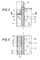
- Fig. 4 eine der Fig. 1 entsprechende Darstellung einer abgewandelten Außenwandkonstruktion und
- Fig. 5 einen Schnitt nach der Linie V-V der Fig. 4.
- 1 shows a building according to the invention in a vertical section through an outer wall,
- 2 shows a section along the line II-II of FIG. 1,
- 3 shows a section along the line III-III of FIG. 1,
- Fig. 4 is a representation corresponding to FIG. 1 of a modified outer wall construction and
- 5 shows a section along the line VV of FIG. 4th
Die in der Zeichnung dargestellte Außenwand 1 eines nicht näher gezeigten Bauwerkes besteht aus einem inneren Wandkörper 2 und einer diesem Wandkörper 2 mit Abstand vorgelagerten Außenverkleidung 3, die nach Fig. 1 aus gegeneinander versetzten Wandplatten und nach Fig. 4 aus einem plattenförmigen Wandkörper, beispielsweise aus Kunststoff oder Metall, aufgebaut ist. Der Aufbau dieser Außenverkleidung kann jedoch auch völlig anders gestaltet sein, da es im Rahmen der Erfindung nur darauf ankommt, daß der Zwischenraum zwischen dem inneren Wandkörper 2 und der Außenverkleidung einen vertikalen Belüftungskanal 4 bildet. Dieser Belüftungskanal 4, der sich zwischen der Außenverkleidung 3 und einer wärmedämmenden Schicht 5 auf der Außenseite des Wandkörpers 2 ergibt, wird nach oben durch ein Steuerorgan 6 verschlossen, das die Luftströmung innerhalb des Belüftungskanales 4 steuert. Dieses Steuerorgan 6 besteht nach den Fig. 1 bis 3 aus einer mit einer Beschattungsvorrichtung 7 für ein Fenster 8 verbundenen Abdeckung 9, die als Fensterbank für das Fenster 8 dient und mit der im Brüstungsbereich zwischen der Außenverkleidung 3 und dem Wandkörper 2 untergebrachte Vorrichtung 7 hochgezogen werden kann, so daß der Belüftungskanal 4 geöffnet wird. Die Beschattungsvorrichtung 7 besteht im Ausführungsbeispiel aus einer Jalousie, deren Lamellen 10 beidseitig in vertikalen Schienen 11 geführt sind und mit einer Betätigungseinrichtung vor das Fenster 8 gezogen werden können, die durch die Pfeile 12 in Fig.:-1 angedeutet ist.The
Durch das Öffnen des Belüftungskanales 4 beim Betätigen der Beschattungsvorrichtung 7 wird eine vertikale Luftströmung sichergestellt, die für eine Wärmeabfuhr zwischen der Außenverkleidung 3 und dem Wandkörper 2 sorgt. Die von außen in die Außenwand 1 eindringende Wärme braucht folglich nicht von der wärmedämmenden Schicht 5, die über eine Dampfsperre 13 an den Wandkörper 2 angeschlossen ist, aufgefangen zu werden, weil sie mit der Luftströmung im Belüftungskanal 4 abgeführt wird. Um eine Aufwärmung des Bauwerkinneren zufolge äußerer Wärmestrahlung zu verhindern, ist es daher unnötig, die wärmedämmende Schicht 5 besonders stark auszubilden, so daß auch die mit einer solchen stark ausgebildeten Wärmedämmschicht verbundenen Nachteile vermieden sind, ohne auf den erwünschten Effekt verzichten zu müssen.By opening the
Wird ein Wärmeverlust aus dem Bauwerkinneren an den Außenraum befürchtet, so wird der Belüftungskanal 4 mit Hilfe des Steuerorgans 6 abgeschlossen. Der im Belüftungskanal 4 eingeschlossene Luftpolster wirkt als zusätzliche Wärmedämmung, so daß auch hinsichtlich der Wärmeübertragung von innen nach außen die erwünschten Dämmwerte sichergestellt werden können, ohne die wärmedämmende Schicht 5 besonders stark ausbilden zu müssen.If a loss of heat from the interior of the building to the outside is feared, the
Gemäß den Fig. 4 und 5 wird das Steuerorgan 6 für den Belüftungskanal 4 nicht durch eine mit einer Abdeckung versehene Beschattungsvorrichtung, sondern durch einen Schieber 14 gebildet, der quer zum Belüftungskanal 4 in einem Gehäuse 15 verschiebbar gelagert ist, das mit gegenseitigem Abstand in Verschieberichtung des Schiebers 14 vorgesehene Durchtrittsöffnungen 16 aufweist, die mit entsprechenden Durchtrittsöffnungen 17 des Schiebers 14 korrespondieren. Durch ein Verschieben des Schiebers 14 können folglich die Durchtrittsöffnungen 16 des den Belüftungskanal 4 abschließenden Gehäuses 15 verschlossen oder geöffnet werden, um den Belüftungskanal 4 für eine Luftströmung zu sperren oder zu öffnen. Dieser Schieber 14 braucht selbstverständlich nicht im Brüstungsbereich eines Fensters 8 angeordnet zu werden, wie dies in den Fig.4 und 5 dargestellt ist. Befindet sich im Bereich eines Belüftungskanales 4 keine Fenster- oder Türöffnung, so wird der Schieber vorzugsweise am oberen Ende der Außenwand anzubringen .sein. Wesentlich ist ja nicht die Lage des Steuerorganes 6, sondern die Steuerbarkeit der Luftströmung innerhalb des sich zwischen der Außenverkleidung 3 und dem inneren Wandkörper 2 ergebenden Belüftungskanales 4.4 and 5, the
Claims (4)
Applications Claiming Priority (2)
| Application Number | Priority Date | Filing Date | Title |
|---|---|---|---|
| AT1233/82 | 1982-03-30 | ||
| AT0123382A AT374227B (en) | 1982-03-30 | 1982-03-30 | CONSTRUCTION |
Publications (3)
| Publication Number | Publication Date |
|---|---|
| EP0090794A2 true EP0090794A2 (en) | 1983-10-05 |
| EP0090794A3 EP0090794A3 (en) | 1984-07-04 |
| EP0090794B1 EP0090794B1 (en) | 1987-09-16 |
Family
ID=3509480
Family Applications (1)
| Application Number | Title | Priority Date | Filing Date |
|---|---|---|---|
| EP19830890043 Expired EP0090794B1 (en) | 1982-03-30 | 1983-03-24 | Building construction |
Country Status (3)
| Country | Link |
|---|---|
| EP (1) | EP0090794B1 (en) |
| AT (1) | AT374227B (en) |
| DE (1) | DE3373689D1 (en) |
Cited By (3)
| Publication number | Priority date | Publication date | Assignee | Title |
|---|---|---|---|---|
| EP0467876A2 (en) * | 1990-07-14 | 1992-01-22 | Rls-Bautechnologie Ag | High-rise building |
| DE4042387A1 (en) * | 1990-10-13 | 1992-04-16 | Alco Systeme Gmbh | CONSTRUCTION |
| EP0481217A2 (en) * | 1990-10-13 | 1992-04-22 | ALCO-Systeme GmbH | Building |
Families Citing this family (3)
| Publication number | Priority date | Publication date | Assignee | Title |
|---|---|---|---|---|
| CH674391A5 (en) * | 1986-12-23 | 1990-05-31 | Sarna Granol Ag | |
| AT403073B (en) * | 1987-06-04 | 1997-11-25 | Jordan Paul Dipl Ing | Process and high-rise building for improving the outside air, in particular city air |
| AT410456B9 (en) * | 2000-12-12 | 2003-12-29 | Consultplan Tech Buero Ges M B | STRUCTURAL CONSTRUCTION WITH A VARIETY OF FLOORS AND PROFILE WITH METAL |
Citations (4)
| Publication number | Priority date | Publication date | Assignee | Title |
|---|---|---|---|---|
| CH64648A (en) * | 1913-01-16 | 1914-04-16 | Reinh Rosenthal Nicolai | Device to avoid temperature equalization between the interior of buildings, vehicles etc. and the outside air |
| FR1036846A (en) * | 1951-05-08 | 1953-09-11 | Screen coating for building walls such as walls or roofs | |
| US4286420A (en) * | 1979-04-18 | 1981-09-01 | Pharmakidis Panayiotis D | Heat retention wall system |
| DE3026635A1 (en) * | 1978-02-27 | 1982-02-11 | Schmidt Reuter Ingenieurgesellschaft mbH & Co KG, 5000 Köln | Ventilated double skinned facade window section - has movable heat screen -pened or closed between skins to duct air |
-
1982
- 1982-03-30 AT AT0123382A patent/AT374227B/en not_active IP Right Cessation
-
1983
- 1983-03-24 DE DE8383890043T patent/DE3373689D1/en not_active Expired
- 1983-03-24 EP EP19830890043 patent/EP0090794B1/en not_active Expired
Patent Citations (4)
| Publication number | Priority date | Publication date | Assignee | Title |
|---|---|---|---|---|
| CH64648A (en) * | 1913-01-16 | 1914-04-16 | Reinh Rosenthal Nicolai | Device to avoid temperature equalization between the interior of buildings, vehicles etc. and the outside air |
| FR1036846A (en) * | 1951-05-08 | 1953-09-11 | Screen coating for building walls such as walls or roofs | |
| DE3026635A1 (en) * | 1978-02-27 | 1982-02-11 | Schmidt Reuter Ingenieurgesellschaft mbH & Co KG, 5000 Köln | Ventilated double skinned facade window section - has movable heat screen -pened or closed between skins to duct air |
| US4286420A (en) * | 1979-04-18 | 1981-09-01 | Pharmakidis Panayiotis D | Heat retention wall system |
Cited By (7)
| Publication number | Priority date | Publication date | Assignee | Title |
|---|---|---|---|---|
| EP0467876A2 (en) * | 1990-07-14 | 1992-01-22 | Rls-Bautechnologie Ag | High-rise building |
| EP0467876A3 (en) * | 1990-07-14 | 1992-07-29 | Rls-Bautechnologie Ag | High-rise building |
| US5347779A (en) * | 1990-07-14 | 1994-09-20 | Rls-Bautechnologie-Ag | High-rise building |
| TR26161A (en) * | 1990-07-14 | 1995-02-15 | Paul Jordan Dipl Ing | HIGH BUILDING WITH A BUILDING WALL AND A BUILDING SHEATH |
| DE4042387A1 (en) * | 1990-10-13 | 1992-04-16 | Alco Systeme Gmbh | CONSTRUCTION |
| EP0481217A2 (en) * | 1990-10-13 | 1992-04-22 | ALCO-Systeme GmbH | Building |
| EP0481217A3 (en) * | 1990-10-13 | 1992-09-02 | Alco-Systeme Gmbh | Building |
Also Published As
| Publication number | Publication date |
|---|---|
| EP0090794A3 (en) | 1984-07-04 |
| DE3373689D1 (en) | 1987-10-22 |
| ATA123382A (en) | 1983-08-15 |
| EP0090794B1 (en) | 1987-09-16 |
| AT374227B (en) | 1984-03-26 |
Similar Documents
| Publication | Publication Date | Title |
|---|---|---|
| DE3216581C2 (en) | Sound and heat insulating composite window with sound insulation ventilation | |
| EP2492432B1 (en) | Roller blind or curtain blind box and thermal insulation insert for same | |
| DE4424524C2 (en) | Facade construction in two-shell construction | |
| EP0090794A2 (en) | Building construction | |
| DE3233499A1 (en) | SOLAR PANELS IN PARTICULAR FOR EXTERNAL WINDOWS | |
| EP0256441B1 (en) | Glazed building element | |
| DE3928259A1 (en) | Window component - has integral ducting and filtration built into frame posts, and contains roller sunblind assembly | |
| DE10033535A1 (en) | double facade | |
| DE2744451A1 (en) | Strip assembled door or window shutter - has strips of paired lamellae overlapping adjacent strips when closed | |
| DE3627096A1 (en) | Glazed structural element, in particular door, having a reversible glass-pane arrangement | |
| DE2420548A1 (en) | Fireproof door or other fire screen wall-sealing element - comprising self-supporting asbestos-cement panels encased in two concentric sheet metal boxes | |
| DE3227721C2 (en) | Roller shutters or sliding shutters for wall openings in buildings | |
| DE2642266A1 (en) | External window solar heat trap - has regulated vertical air circulation through space between transparent frame held layers | |
| DE3013440A1 (en) | Ventilating window or door has acoustically insulating ducts - pref. contg. filters in top and bottom frame members | |
| EP0005259B1 (en) | Air conditioning system for a closed space | |
| EP0481217B1 (en) | Building | |
| EP0087806B1 (en) | Roller shutter for the airtight covering of wall openings by the formation of at least one static air layer | |
| DE2842476C2 (en) | Interior shading for greenhouses | |
| DE3422439C2 (en) | Window with a window frame to be built into a building wall and a casement arranged in it | |
| DE3347583A1 (en) | Fireproof window wall | |
| DE202016008921U1 (en) | Window insulation element | |
| DE8309181U1 (en) | WINDOW AND / OR SHUTTER BOX ELEMENT | |
| DE8327232U1 (en) | SHUTTER FOR COVERING A WALL OPENING | |
| DE2626850A1 (en) | Double glazed window with internal insulating venetian blind - has slats overlapped to form sealed walling units enclosing air space | |
| DE2546044C3 (en) | Process for air conditioning buildings with individual regulation of the individual rooms |
Legal Events
| Date | Code | Title | Description |
|---|---|---|---|
| PUAI | Public reference made under article 153(3) epc to a published international application that has entered the european phase |
Free format text: ORIGINAL CODE: 0009012 |
|
| AK | Designated contracting states |
Kind code of ref document: A2 Designated state(s): BE CH DE FR GB IT LI LU NL SE Designated state(s): BE CH DE FR GB IT LI LU NL SE |
|
| PUAL | Search report despatched |
Free format text: ORIGINAL CODE: 0009013 |
|
| AK | Designated contracting states |
Kind code of ref document: A3 Designated state(s): BE CH DE FR GB IT LI LU NL SE Designated state(s): BE CH DE FR GB IT LI LU NL SE |
|
| 17P | Request for examination filed |
Effective date: 19841205 |
|
| GRAA | (expected) grant |
Free format text: ORIGINAL CODE: 0009210 |
|
| AK | Designated contracting states |
Kind code of ref document: B1 Designated state(s): BE CH DE FR GB IT LI LU NL SE |
|
| REF | Corresponds to: |
Ref document number: 3373689 Country of ref document: DE Date of ref document: 19871022 |
|
| ET | Fr: translation filed | ||
| GBT | Gb: translation of ep patent filed (gb section 77(6)(a)/1977) | ||
| ITF | It: translation for a ep patent filed |
Owner name: MODIANO & ASSOCIATI S.R.L. |
|
| PLBE | No opposition filed within time limit |
Free format text: ORIGINAL CODE: 0009261 |
|
| STAA | Information on the status of an ep patent application or granted ep patent |
Free format text: STATUS: NO OPPOSITION FILED WITHIN TIME LIMIT |
|
| 26N | No opposition filed | ||
| ITTA | It: last paid annual fee | ||
| EPTA | Lu: last paid annual fee | ||
| EAL | Se: european patent in force in sweden |
Ref document number: 83890043.9 |
|
| PGFP | Annual fee paid to national office [announced via postgrant information from national office to epo] |
Ref country code: LU Payment date: 19960301 Year of fee payment: 14 |
|
| PGFP | Annual fee paid to national office [announced via postgrant information from national office to epo] |
Ref country code: SE Payment date: 19960326 Year of fee payment: 14 |
|
| PGFP | Annual fee paid to national office [announced via postgrant information from national office to epo] |
Ref country code: NL Payment date: 19960329 Year of fee payment: 14 |
|
| PGFP | Annual fee paid to national office [announced via postgrant information from national office to epo] |
Ref country code: CH Payment date: 19960401 Year of fee payment: 14 |
|
| PGFP | Annual fee paid to national office [announced via postgrant information from national office to epo] |
Ref country code: BE Payment date: 19960412 Year of fee payment: 14 |
|
| PG25 | Lapsed in a contracting state [announced via postgrant information from national office to epo] |
Ref country code: LU Free format text: LAPSE BECAUSE OF NON-PAYMENT OF DUE FEES Effective date: 19970324 |
|
| PG25 | Lapsed in a contracting state [announced via postgrant information from national office to epo] |
Ref country code: SE Effective date: 19970325 |
|
| PGFP | Annual fee paid to national office [announced via postgrant information from national office to epo] |
Ref country code: FR Payment date: 19970328 Year of fee payment: 15 |
|
| PG25 | Lapsed in a contracting state [announced via postgrant information from national office to epo] |
Ref country code: LI Effective date: 19970331 Ref country code: CH Effective date: 19970331 Ref country code: BE Effective date: 19970331 |
|
| PGFP | Annual fee paid to national office [announced via postgrant information from national office to epo] |
Ref country code: GB Payment date: 19970401 Year of fee payment: 15 |
|
| BERE | Be: lapsed |
Owner name: JORDAN PAUL DIPL.-ING. Effective date: 19970331 |
|
| PG25 | Lapsed in a contracting state [announced via postgrant information from national office to epo] |
Ref country code: NL Effective date: 19971001 |
|
| REG | Reference to a national code |
Ref country code: CH Ref legal event code: PL |
|
| NLV4 | Nl: lapsed or anulled due to non-payment of the annual fee |
Effective date: 19971001 |
|
| EUG | Se: european patent has lapsed |
Ref document number: 83890043.9 |
|
| PG25 | Lapsed in a contracting state [announced via postgrant information from national office to epo] |
Ref country code: GB Free format text: LAPSE BECAUSE OF NON-PAYMENT OF DUE FEES Effective date: 19980324 |
|
| PG25 | Lapsed in a contracting state [announced via postgrant information from national office to epo] |
Ref country code: FR Free format text: THE PATENT HAS BEEN ANNULLED BY A DECISION OF A NATIONAL AUTHORITY Effective date: 19980331 |
|
| GBPC | Gb: european patent ceased through non-payment of renewal fee |
Effective date: 19980324 |
|
| REG | Reference to a national code |
Ref country code: FR Ref legal event code: ST |
|
| PGFP | Annual fee paid to national office [announced via postgrant information from national office to epo] |
Ref country code: DE Payment date: 20020320 Year of fee payment: 20 |