EP0005259B1 - Air conditioning system for a closed space - Google Patents
Air conditioning system for a closed space Download PDFInfo
- Publication number
- EP0005259B1 EP0005259B1 EP79101318A EP79101318A EP0005259B1 EP 0005259 B1 EP0005259 B1 EP 0005259B1 EP 79101318 A EP79101318 A EP 79101318A EP 79101318 A EP79101318 A EP 79101318A EP 0005259 B1 EP0005259 B1 EP 0005259B1
- Authority
- EP
- European Patent Office
- Prior art keywords
- inner glazing
- air
- sun
- glazing
- air exhaust
- Prior art date
- Legal status (The legal status is an assumption and is not a legal conclusion. Google has not performed a legal analysis and makes no representation as to the accuracy of the status listed.)
- Expired
Links
- 238000004378 air conditioning Methods 0.000 title description 7
- 230000005855 radiation Effects 0.000 claims abstract description 11
- 230000000475 sunscreen effect Effects 0.000 claims abstract 13
- 239000000516 sunscreening agent Substances 0.000 claims abstract 13
- 239000011248 coating agent Substances 0.000 claims description 5
- 238000000576 coating method Methods 0.000 claims description 5
- 238000000605 extraction Methods 0.000 description 22
- 238000009833 condensation Methods 0.000 description 3
- 230000005494 condensation Effects 0.000 description 3
- 238000010521 absorption reaction Methods 0.000 description 2
- 238000010276 construction Methods 0.000 description 2
- 238000010438 heat treatment Methods 0.000 description 2
- 230000037072 sun protection Effects 0.000 description 2
- 241001295925 Gegenes Species 0.000 description 1
- 230000015572 biosynthetic process Effects 0.000 description 1
- 230000000694 effects Effects 0.000 description 1
- 230000000630 rising effect Effects 0.000 description 1
- 238000007789 sealing Methods 0.000 description 1
- 210000002023 somite Anatomy 0.000 description 1
Images
Classifications
-
- E—FIXED CONSTRUCTIONS
- E06—DOORS, WINDOWS, SHUTTERS, OR ROLLER BLINDS IN GENERAL; LADDERS
- E06B—FIXED OR MOVABLE CLOSURES FOR OPENINGS IN BUILDINGS, VEHICLES, FENCES OR LIKE ENCLOSURES IN GENERAL, e.g. DOORS, WINDOWS, BLINDS, GATES
- E06B7/00—Special arrangements or measures in connection with doors or windows
- E06B7/02—Special arrangements or measures in connection with doors or windows for providing ventilation, e.g. through double windows; Arrangement of ventilation roses
- E06B7/10—Special arrangements or measures in connection with doors or windows for providing ventilation, e.g. through double windows; Arrangement of ventilation roses by special construction of the frame members
-
- E—FIXED CONSTRUCTIONS
- E06—DOORS, WINDOWS, SHUTTERS, OR ROLLER BLINDS IN GENERAL; LADDERS
- E06B—FIXED OR MOVABLE CLOSURES FOR OPENINGS IN BUILDINGS, VEHICLES, FENCES OR LIKE ENCLOSURES IN GENERAL, e.g. DOORS, WINDOWS, BLINDS, GATES
- E06B7/00—Special arrangements or measures in connection with doors or windows
- E06B7/02—Special arrangements or measures in connection with doors or windows for providing ventilation, e.g. through double windows; Arrangement of ventilation roses
-
- F—MECHANICAL ENGINEERING; LIGHTING; HEATING; WEAPONS; BLASTING
- F24—HEATING; RANGES; VENTILATING
- F24F—AIR-CONDITIONING; AIR-HUMIDIFICATION; VENTILATION; USE OF AIR CURRENTS FOR SCREENING
- F24F5/00—Air-conditioning systems or apparatus not covered by F24F1/00 or F24F3/00, e.g. using solar heat or combined with household units such as an oven or water heater
- F24F5/0075—Systems using thermal walls, e.g. double window
-
- F—MECHANICAL ENGINEERING; LIGHTING; HEATING; WEAPONS; BLASTING
- F24—HEATING; RANGES; VENTILATING
- F24F—AIR-CONDITIONING; AIR-HUMIDIFICATION; VENTILATION; USE OF AIR CURRENTS FOR SCREENING
- F24F7/00—Ventilation
- F24F7/04—Ventilation with ducting systems, e.g. by double walls; with natural circulation
-
- F—MECHANICAL ENGINEERING; LIGHTING; HEATING; WEAPONS; BLASTING
- F24—HEATING; RANGES; VENTILATING
- F24S—SOLAR HEAT COLLECTORS; SOLAR HEAT SYSTEMS
- F24S20/00—Solar heat collectors specially adapted for particular uses or environments
- F24S20/60—Solar heat collectors integrated in fixed constructions, e.g. in buildings
- F24S20/63—Solar heat collectors integrated in fixed constructions, e.g. in buildings in the form of windows
-
- E—FIXED CONSTRUCTIONS
- E06—DOORS, WINDOWS, SHUTTERS, OR ROLLER BLINDS IN GENERAL; LADDERS
- E06B—FIXED OR MOVABLE CLOSURES FOR OPENINGS IN BUILDINGS, VEHICLES, FENCES OR LIKE ENCLOSURES IN GENERAL, e.g. DOORS, WINDOWS, BLINDS, GATES
- E06B7/00—Special arrangements or measures in connection with doors or windows
- E06B7/02—Special arrangements or measures in connection with doors or windows for providing ventilation, e.g. through double windows; Arrangement of ventilation roses
- E06B2007/026—Special arrangements or measures in connection with doors or windows for providing ventilation, e.g. through double windows; Arrangement of ventilation roses with air flow between panes
-
- Y—GENERAL TAGGING OF NEW TECHNOLOGICAL DEVELOPMENTS; GENERAL TAGGING OF CROSS-SECTIONAL TECHNOLOGIES SPANNING OVER SEVERAL SECTIONS OF THE IPC; TECHNICAL SUBJECTS COVERED BY FORMER USPC CROSS-REFERENCE ART COLLECTIONS [XRACs] AND DIGESTS
- Y02—TECHNOLOGIES OR APPLICATIONS FOR MITIGATION OR ADAPTATION AGAINST CLIMATE CHANGE
- Y02A—TECHNOLOGIES FOR ADAPTATION TO CLIMATE CHANGE
- Y02A30/00—Adapting or protecting infrastructure or their operation
-
- Y—GENERAL TAGGING OF NEW TECHNOLOGICAL DEVELOPMENTS; GENERAL TAGGING OF CROSS-SECTIONAL TECHNOLOGIES SPANNING OVER SEVERAL SECTIONS OF THE IPC; TECHNICAL SUBJECTS COVERED BY FORMER USPC CROSS-REFERENCE ART COLLECTIONS [XRACs] AND DIGESTS
- Y02—TECHNOLOGIES OR APPLICATIONS FOR MITIGATION OR ADAPTATION AGAINST CLIMATE CHANGE
- Y02B—CLIMATE CHANGE MITIGATION TECHNOLOGIES RELATED TO BUILDINGS, e.g. HOUSING, HOUSE APPLIANCES OR RELATED END-USER APPLICATIONS
- Y02B10/00—Integration of renewable energy sources in buildings
- Y02B10/20—Solar thermal
-
- Y—GENERAL TAGGING OF NEW TECHNOLOGICAL DEVELOPMENTS; GENERAL TAGGING OF CROSS-SECTIONAL TECHNOLOGIES SPANNING OVER SEVERAL SECTIONS OF THE IPC; TECHNICAL SUBJECTS COVERED BY FORMER USPC CROSS-REFERENCE ART COLLECTIONS [XRACs] AND DIGESTS
- Y02—TECHNOLOGIES OR APPLICATIONS FOR MITIGATION OR ADAPTATION AGAINST CLIMATE CHANGE
- Y02B—CLIMATE CHANGE MITIGATION TECHNOLOGIES RELATED TO BUILDINGS, e.g. HOUSING, HOUSE APPLIANCES OR RELATED END-USER APPLICATIONS
- Y02B30/00—Energy efficient heating, ventilation or air conditioning [HVAC]
- Y02B30/90—Passive houses; Double facade technology
-
- Y—GENERAL TAGGING OF NEW TECHNOLOGICAL DEVELOPMENTS; GENERAL TAGGING OF CROSS-SECTIONAL TECHNOLOGIES SPANNING OVER SEVERAL SECTIONS OF THE IPC; TECHNICAL SUBJECTS COVERED BY FORMER USPC CROSS-REFERENCE ART COLLECTIONS [XRACs] AND DIGESTS
- Y02—TECHNOLOGIES OR APPLICATIONS FOR MITIGATION OR ADAPTATION AGAINST CLIMATE CHANGE
- Y02E—REDUCTION OF GREENHOUSE GAS [GHG] EMISSIONS, RELATED TO ENERGY GENERATION, TRANSMISSION OR DISTRIBUTION
- Y02E10/00—Energy generation through renewable energy sources
- Y02E10/40—Solar thermal energy, e.g. solar towers
Definitions
- the invention relates to a device for the air conditioning of a closed space, which has on its outside the outside glazing, which forms an exhaust air duct with a spacing from the inside of the inside of the room includes, which is connected via a closable air extraction opening with said exhaust duct.
- the air extraction opening mentioned can be closed by an air control flap.
- exhaust air flows exclusively from the closed space through the space between the sun blind or roller blind and the inner glazing and from there into a suction box into which the exhaust air duct also opens.
- the air control flap shown in FIG. 2 of this prior publication the exhaust air flows exclusively through the exhaust air duct and from there into the suction box mentioned. Since the air control flap can also take intermediate positions, there are correspondingly distributed suction quantities over the flow paths described.
- the room air humidity and the intensity of the incidence of solar radiation can also be included as parameters for the control of the air control flap and thus the proportions of the air extracted through the two channels.
- the total amount of air extracted via the suction box should usually remain constant and is, for example, 100 m 3 / h.
- the entire amount of air would be extracted as exhaust air through the exhaust air duct. If the air control flap were to open the internal exhaust air duct a little, a partial amount of air would be extracted from the internal duct. The air extracted from the exhaust air duct would be reduced by precisely this amount of partial air if the total amount of air extracted should remain constant.
- the exhaust air flowing through the exhaust air duct changes in quantity depending on the respective position of the air control flap. Since the flow cross-section of the exhaust air duct remains constant, different flow conditions inevitably have to occur in this exhaust air duct with changing air quantities per unit of time. It is therefore impossible to achieve a largely laminar flow.
- Another disadvantage is that the sun blind or the aforementioned blind is not used specifically for the air conditioning of the room.
- a further disadvantage is that the room temperature, the outside air temperature, the room air humidity and / or the intensity of the incidence of solar radiation are used to control the air control flap. So it would basically be possible to pivot the air control flap into the position shown in FIG. 1 of the prior publication (complete closure of the exhaust air duct), even though, for example, the roller blind is pulled up, so there is no internal exhaust air duct for the exhaust air.
- the invention is therefore based on the object of improving the device described in the introduction in such a way that condensation on the inside of the outer glazing is prevented with certainty and the air conditioning of the room is improved.
- laminar air flows have already become known from DE-A-25 18 252 in comparable air conditioning devices. According to the teaching disclosed in this prior publication, a largely laminar flow should take place in a space between the panels. Appropriate air baffles are provided for this. The warm air flowing out of this space between the panels is directed against the inner surface of the outer pane via nozzle-like inserts in order to effectively prevent fogging. The warm air rising here is then to be directed into the exhaust air duct without formation of eddies through nozzle-like inserts inserted in outlet openings.
- the overall combination claimed according to the invention achieves significant advantages: it is essential for the invention to generate a defined, largely laminar air flow in the exhaust air duct.
- the optimal distance between the outer and inner glazing is calculated taking into account the lowest outside temperature to be expected in winter, the desired relative air humidity in the interior, the desired interior temperature, the air volume provided, the heat emission from the interior to the exterior, and the desired surface temperature the sun blind in winter, the desired or required air volume in the interior and taking into account the location and the orientation of the room to be air-conditioned (climate of the country, orientation of the building facade, e.g. to the south or north, etc.)
- the surface temperature of the sun blind on the inside of the room should be as close as possible to the room temperature.
- the defined air flow through the exhaust air duct is sufficient to maintain a temperature of 19 ° C on the inner glazing at a room temperature of 22 ° C and an outside temperature of - 15 ° C.
- the inner glazing heats up to e.g. 48 ° C. This leads to a temperature of around 32 ° C on the surface of the sun blind. According to the invention, this temperature can now be reduced to approximately room temperature by suctioning off the air located between the inner glazing and sun blinds.
- a further advantage is achieved by the inventive feature c): the parameters which result directly from the space between the inner glazing and sun blinds are now used for the control. Pulling up the sun blind always closes the air extraction opening.
- the inventive feature d) ensures that the same amount of air always flows through the exhaust air duct regardless of the control of the air extraction opening.
- the total air flow flowing through the exhaust air duct is now composed of a portion that comes from the room or a separate air conditioning system and a portion that is extracted from the intermediate space. Therefore, the flow conditions in the exhaust air duct are always the same; The set laminar air flow can therefore be maintained in all operating conditions.
- the control of the suction cross-sections of the air extraction openings for the space between the inner glazing and sun blind can be done in different ways.
- the sun blind When the sun blind is lowered, its weight in the end position of the sun blind can be pressed by a button or the like, which opens the air extraction openings via a linkage.
- the weight of the sun blind can also operate a switch, which causes an electrical opening of the air extraction openings.
- electromagnets can be applied, which or the like via a linkage. open the air extraction openings.
- an expansion rod for example made of plastic, with a high expansion coefficient can be provided, which controls the suction cross section of the air suction openings via the space temperature. It is also possible to apply a servomotor to adjust the air extraction openings via a temperature sensor.
- the air extraction openings can be designed as slots and are preferably always installed where the air is most energetic.
- the surface of the sun blind facing the inner glazing can have sections which absorb the solar radiation striking in winter.
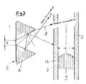
- This can e.g. can be achieved by profiling arranged on the surface of the sun blind facing the inner glazing, which reflect the incident sun rays directly or indirectly via neighboring profiling against the inner glazing, a selective coating being arranged between the profiling so that it is only exposed to sun rays when the sun is low.
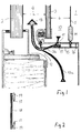
- a room 1 to be ventilated or to be air-conditioned has outer glazing 2 on its outside, which forms an exhaust air duct 4 with an inner glazing 3 arranged at a distance a from the inside of the room.
- a sun blind 5 is arranged at a distance b on the inside of the inner glazing 3.
- the sun rays 8 which fall in a correspondingly flat manner at a low position of the sun can impinge directly on the strip-shaped area 9 or are reflected by the profiles 6 on this strip-shaped area 9. Because of the selective coating provided here, the strip-shaped areas 9 thus have a correspondingly increased absorption and thus a heating of the stores, which can be used to heat the room 1.
- the distance a between the outer glazing 2 and the inner glazing 3 is dimensioned such that a defined, largely laminar air flow is established in the exhaust air duct 4.
- FIG. 1 shows that closable air extraction openings 11 are provided in the space 10 formed between the inner glazing 3 and the sun blind 5, the opening of which is controlled as a function of the position of the sun blind and / or the temperature in this space 10.
- the air extraction openings 11 open into the intake duct 12 of the exhaust air duct 4.
- the total air flow 13 flowing through the exhaust air duct 4 is thus composed of a portion 13a that comes from the room 1 or a separate air conditioning system and a portion 13b that is extracted from the intermediate space 10.
- the energy between the inner glazing 3 and the sun blind 5 is dissipated with the partial air flow 13b.
- FIG. 1 shows an example for controlling the air extraction openings 11.
- a weight 14 attached to its lower edge presses on a lever 15 which is pulled against the air extraction openings 11 by a spring 16 with a sealing strip 17 in the closed position.
- the lever 15 is pressed down and thereby releases the air extraction openings 11.
- FIG. 2 schematically shows a modified embodiment for controlling the air extraction openings 11.
- the control consists of an expansion rod 18, which is in the space 10 between the inner glazing 3 and Sun blind 5 is arranged and carries slide 19 which, depending on the expansion of the expansion rod 18, continuously increase or decrease the cross section of the air extraction openings 11.
Landscapes
- Engineering & Computer Science (AREA)
- Chemical & Material Sciences (AREA)
- General Engineering & Computer Science (AREA)
- Mechanical Engineering (AREA)
- Combustion & Propulsion (AREA)
- Life Sciences & Earth Sciences (AREA)
- Sustainable Development (AREA)
- Structural Engineering (AREA)
- Civil Engineering (AREA)
- Physics & Mathematics (AREA)
- Sustainable Energy (AREA)
- Thermal Sciences (AREA)
- Blinds (AREA)
- Specific Sealing Or Ventilating Devices For Doors And Windows (AREA)
Abstract
Description
Die Erfindung betrifft eine Einrichtung zur Klimatisierung eines geschlossenen Raumes, der auf seiner Wetteraußenseite eine Außenverglasung aufweist, die mit einer im Abstand von ihr rauminnenseitig angeordneten Innenverglasung einen Abluftkanal bildet, wobei auf der Rauminnenseite der Innenverglasung ein Sonnenstore vorgesehen ist, der mit der Innenverglasung einen Zwischenraum einschließt, der über eine verschließbare Luftabsaugöffnung mit dem genannten Abluftkanal in Verbindung steht.The invention relates to a device for the air conditioning of a closed space, which has on its outside the outside glazing, which forms an exhaust air duct with a spacing from the inside of the inside of the room includes, which is connected via a closable air extraction opening with said exhaust duct.
Eine derartige Ausführungsform läßt sich der DE-A-26 32 669 entnehmen. Die genannte Luftabsaugöffnung ist über eine Luftregelklappe verschließbar. Bei der in Figur 1 dieser Druckschrift dargestellten Stellung dieser Luftregelklappe strömt aus dem geschlossenen Raum Abluft ausschließlich durch den Zwischenraum zwischen Sonnenstore bzw. Rollo und Innenverglasung und von dort in einen Absaugkasten, in den auch der Abluftkanal mündet. Bei der in Figur 2 dieser Vorveröffentlichung dargestellten Stellung der Luftregelklappe strömt die Abluft ausschließlich durch den Abluftkanal und von dort in den genannten Absaugkasten. Da die Luftregelklappe auch Zwischenstellungen einnehmen kann, ergeben sich entsprechend prozentual verteilte Absaugmengen über die beschriebenen Strömungswege. Dabei können als Parameter für die Steuerung der Luftregelklappe und damit der Mengenverhältnisse der durch die beiden Kanäle abgesaugten Luft neben der Raumtemperatur und der Außenlufttemperatur auch noch die Raumluftfeuchte und die Intensität des Einfalls der Sonnenstrahlung mit einbezogen werden.Such an embodiment can be found in DE-A-26 32 669. The air extraction opening mentioned can be closed by an air control flap. In the position of this air control flap shown in FIG. 1 of this document, exhaust air flows exclusively from the closed space through the space between the sun blind or roller blind and the inner glazing and from there into a suction box into which the exhaust air duct also opens. In the position of the air control flap shown in FIG. 2 of this prior publication, the exhaust air flows exclusively through the exhaust air duct and from there into the suction box mentioned. Since the air control flap can also take intermediate positions, there are correspondingly distributed suction quantities over the flow paths described. In addition to the room temperature and the outside air temperature, the room air humidity and the intensity of the incidence of solar radiation can also be included as parameters for the control of the air control flap and thus the proportions of the air extracted through the two channels.
Die über dem Absaugkasten insgesamt abgesaugte Luftmenge soll üblicherweise konstant bleiben und beträgt beispielsweise 100 m3/h. Bei dem in Figur 2 der genannten Vorveröffentlichung dargestellten Winterbetrieb würde die gesamte Luftmenge als Abluft durch den Abluftkanal abgesaugt werden. Würde dann die Luftregelklappe den innenliegenden Abluftkanal etwas öffnen, würde eine Teilluftmenge aus dem innenliegenden Kanal abgesaugt werden. Um eben diese Teilluftmenge würde die aus dem Abluftkanal abgesaugte Luft verringert werden, wenn die insgesamt abgesaugte Luftmenge konstant bleiben soll. Bei dieser vorbekannten Konstruktion ändert sich also die durch den Abluftkanal strömende Abluft mengenmäßig in Abhängigkeit von der jeweiligen Stellung der Luftregelklappe. Da der Strömungsquerschnitt des Abluftkanals konstant bleibt, müssen sich bei wechselnden Luftmengen pro Zeiteinheit in diesem Abluftkanal zwangsläufig unterschiedliche Strömungsverhältnisse einstellen. Die Erzielung einer weitgehend laminaren Strömung ist somit ausgeschlossen.The total amount of air extracted via the suction box should usually remain constant and is, for example, 100 m 3 / h. In the winter operation shown in FIG. 2 of the aforementioned prior publication, the entire amount of air would be extracted as exhaust air through the exhaust air duct. If the air control flap were to open the internal exhaust air duct a little, a partial amount of air would be extracted from the internal duct. The air extracted from the exhaust air duct would be reduced by precisely this amount of partial air if the total amount of air extracted should remain constant. In this known construction, the exhaust air flowing through the exhaust air duct changes in quantity depending on the respective position of the air control flap. Since the flow cross-section of the exhaust air duct remains constant, different flow conditions inevitably have to occur in this exhaust air duct with changing air quantities per unit of time. It is therefore impossible to achieve a largely laminar flow.
Ein wesentlicher Nachteil bei der Ausführungsform gemäß der DE-A-26 32 669 ist darin zu sehen, daß sich in dem Abluftkanal unkontrollierte Luftverwirbelungen ergeben. Dies ist nachteilig hinsichtlich der auf der Rauminnenseite der Außenverglasung unter allen Umständen zu verhindernden Kondensierung sowie hinsichtlich der im Sommer aus dem Abluftkanal abzutransportierenden Wärmeenergie.A major disadvantage of the embodiment according to DE-A-26 32 669 can be seen in the fact that uncontrolled air turbulence results in the exhaust air duct. This is disadvantageous with regard to the condensation to be prevented under all circumstances on the inside of the outer glazing and with regard to the thermal energy to be removed from the exhaust air duct in summer.
Nachteilig ist ferner, daß der Sonnenstore bzw. das genannte Rollo nicht gezielt für die Klimatisierung des Raumes eingesetzt wird.Another disadvantage is that the sun blind or the aforementioned blind is not used specifically for the air conditioning of the room.
Nachteilig ist darüber hinaus, daß für die Steuerung der Luftregelklappe die Raumtemperatur, die Außenlufttemperatur, die Raumluftfeuchte und/oder die Intensität des Einfalls der Sonnenstrahlung herangezogen werden. So wäre es also grundsätzlich möglich, die Luftregelklappe in die in Figur 1 der Vorveröffentlichung dargestellte Position zu verschwenken (vollständiger Abschluß des Abluftkanals), obwohl beispielsweise das Rollo hochgezogen ist, also gar kein innerer Abluftkanal für die Abluft existiert.A further disadvantage is that the room temperature, the outside air temperature, the room air humidity and / or the intensity of the incidence of solar radiation are used to control the air control flap. So it would basically be possible to pivot the air control flap into the position shown in FIG. 1 of the prior publication (complete closure of the exhaust air duct), even though, for example, the roller blind is pulled up, so there is no internal exhaust air duct for the exhaust air.
Der Erfindung liegt somit die Aufgabe zugrunde, die eingangs beschriebene Einrichtung so zu verbessern, daß eine Kondensierung auf der Rauminnenseite der Außenverglasung mit Sicherheit verhindert und die Klimatisierung des Raumes verbessert werden.The invention is therefore based on the object of improving the device described in the introduction in such a way that condensation on the inside of the outer glazing is prevented with certainty and the air conditioning of the room is improved.
Diese Aufgabe wird gemäß der Erfindung durch folgende Merkmale gelöst :
- a) Der Abstand a zwischen Außen- und Innenverglasung ist nur so groß, daß sich im Abluftkanal eine definierte, weitgehend laminare Luftströmung einstellt ;
- b) die der Innenverglasung zugekehrte Fläche des Sonnenstores ist so ausgebildet, daß ein möglichst großer Anteil der auftreffenden Sonnenstrahlung gegen die Innenverglasung reflektiert wird ;
- c) die Öffnung der verschließbaren Luftabsaugöffnung wird in Abhängigkeit von der Stellung des Sonnenstores und/oder der Temperatur in dem Zwischenraum zwischen Innenverglasung und Sonnenstore gesteuert ;
- d) die Luftabsaugöffnungen münden in den Absaugkanal des Abluftkanals.
- a) The distance a between the outer and inner glazing is only so large that a defined, largely laminar air flow occurs in the exhaust air duct;
- b) the surface of the sun blind facing the inner glazing is designed such that the largest possible proportion of the incident solar radiation is reflected against the inner glazing;
- c) the opening of the closable air extraction opening is controlled depending on the position of the sun blind and / or the temperature in the space between the inner glazing and the sun blind;
- d) the air extraction openings open into the extraction duct of the exhaust air duct.
Grundsätzlich sind laminare Luftströmungen bereits durch die DE-A-25 18 252 bei vergleichbaren Klimatisierungseinrichtungen bekanntgeworden. Gemäß der in dieser Vorveröffentlichung offenbarten Lehre soll in einem Paneelzwischenraum eine weitgehend laminare Strömung stattfinden. Hierfür sind entsprechende Luftleitbleche vorgesehen. Die aus diesem Paneelzwischenraum ausströmende Warmluft wird über düsenartige Einsätze gegen die Innenfläche der Außenscheibe geleitet, um ein Beschlagen derselben wirksam zu verhindern. Die hier aufsteigende Warmluft soll dann ohne Wirbelbildung durch in Austrittsöffnungen eingesetzte düsenartige Einsätze in den Abluftkanal geleitet werden.Basically, laminar air flows have already become known from DE-A-25 18 252 in comparable air conditioning devices. According to the teaching disclosed in this prior publication, a largely laminar flow should take place in a space between the panels. Appropriate air baffles are provided for this. The warm air flowing out of this space between the panels is directed against the inner surface of the outer pane via nozzle-like inserts in order to effectively prevent fogging. The warm air rising here is then to be directed into the exhaust air duct without formation of eddies through nozzle-like inserts inserted in outlet openings.
Die bei dieser vorbekannten Einrichtung angestrebte laminare Strömung soll also nicht zwischen Außen- und Innenverglasung erfolgen. Eine laminare Strömung innerhalb des Abluftkanals wäre bei dieser vorbekannten Einrichtung auch theoretisch nicht möglich, da dieser Abluftkanal eine erheblich größere Breite aufweist als der Paneelzwischenraum. Wenn in letzterem eine laminare Strömung herrschen soll, so kann bereits aufgrund der Vergrößerung des Strömungsquerschnitts nicht auch im Abluftkanal eine laminare Strömung herrschen, zumal die aus dem Paneelzwischenraum laminar ankommende Luftströmung durch die genannten Düsen gedrückt und unmittelbar gegen die Innenseite der Außenverglasung geleitet werden soll.The at this previously known facility the desired laminar flow should not therefore occur between the outer and inner glazing. A laminar flow within the exhaust air duct would also theoretically not be possible with this previously known device, since this exhaust air duct has a considerably larger width than the space between the panels. If a laminar flow is to prevail in the latter, a laminar flow cannot prevail even in the exhaust air duct due to the enlargement of the flow cross-section, especially since the laminar air flow coming from the panel space is to be pressed through the nozzles mentioned and directed directly against the inside of the outer glazing.
Ein Reflektieren der Sonnenstrahlung entsprechend dem oben zitierten Erfindungsmerkmal b) ist grundsätzlich durch die DE-B-1266472 bekanntgeworden. Jedoch ist bei dieser Einrichtung nur eine einzige Verglasung vorgesehen, so daß kein zwischen Außen- und Innenverglasung gebildeter Abluftkanal vorhanden ist. Die konstruktion zeigt, daß ein Sonnenschutzvorhang einen Belag aufweisen kann, der zusätzlich eine Reflexion der Strahlung aus der Fensterzone übernimmt, und daß zwischen der Verglasung und dem Sonnenschutzvorhang ein Zwischenraum vorgesehen ist, dessen Luftabsaugöffnung in Abhängigkeit von der Stellung des Sonnenstoren veränderbar ist.Reflecting the solar radiation in accordance with the inventive feature b) cited has become known in principle from DE-B-1266472. However, only a single glazing is provided in this device, so that there is no exhaust air duct formed between the outer and inner glazing. The construction shows that a sun protection curtain can have a covering which additionally takes over a reflection of the radiation from the window zone, and that an intermediate space is provided between the glazing and the sun protection curtain, the air suction opening of which can be changed depending on the position of the sun blind.
Durch die erfindungsgemäß beanspruchte Gesamtkombination werden wesentliche Vorteile erreicht: Wesentlich für die Erfindung ist dabei, im Abluftkanal eine definierte, weitgehend laminare Luftströmung zu erzeugen. Dabei erfolgt die Berechnung des optimalen Abstandes zwischen Außen- und Innenverglasung unter Berücksichtigung der im Winter zu erwartenden tiefsten Außentemperatur, der gewünschten relativen Luftfeuchtigkeit im Innenraum, der gewünschten Innenraumtemperatur, der zur Verfügung gestellten Luftmengen, der Wärmeabgabe des Innenraumes an den Außenraum, der gewünschten Oberflächentemperatur des Sonnenstoren im Winter, der gewünschten bzw. erforderlichen Luftmengen im Innenraum sowie unter Berücksichtigung des Standortes sowie der Orientierung des zu klimatisierenden Raumes (Klima des Landes, Orientierung der Gebäudefassade z.B. nach Süden oder Norden u.dgl.).The overall combination claimed according to the invention achieves significant advantages: it is essential for the invention to generate a defined, largely laminar air flow in the exhaust air duct. The optimal distance between the outer and inner glazing is calculated taking into account the lowest outside temperature to be expected in winter, the desired relative air humidity in the interior, the desired interior temperature, the air volume provided, the heat emission from the interior to the exterior, and the desired surface temperature the sun blind in winter, the desired or required air volume in the interior and taking into account the location and the orientation of the room to be air-conditioned (climate of the country, orientation of the building facade, e.g. to the south or north, etc.)
Als Richtwert für den Abstand zwischen Außen-und Innenverglasung ergibt sich ein Wert von etwa 40 mm, während in einer üblichen Abluftfassade der Abluftkanal eine Tiefe von etwa 200 mm aufweist. Durch diese Verringerung der Tiefe des Abluftkanals erhält man einerseits eine entsprechend geringere Bautiefe, die zu entsprechenden Kosteneinsparungen führt. Außerdem aber erhält man eine laminare Luftströmung (die turbulente Grenzströmung an den Wandungen des Abluftkanals kann hier unberücksichtigt bleiben). Hierdurch ergibt sich eine starke Verringerung des Energieverlustes der Luft im Winter. Außerdem erhält man ein definiertes Temperaturprofil von der Wetteraußenseite zur Rauminnenseite der Außenverglasung und kann dadurch in Verbindung mit der erhöhten Strömungsgeschwindigkeit eine Kondensatbildung auf der Innenseite der Außenverglasung sicher verhindern.As a guideline for the distance between the outer and inner glazing, a value of approximately 40 mm results, while in a conventional exhaust air facade the exhaust air duct has a depth of approximately 200 mm. This reduction in the depth of the exhaust air duct results in a correspondingly smaller overall depth, which leads to corresponding cost savings. In addition, however, a laminar air flow is obtained (the turbulent limiting flow on the walls of the exhaust air duct can be disregarded here). This results in a strong reduction in the energy loss in the air in winter. In addition, a defined temperature profile is obtained from the outside of the weather to the inside of the outer glazing and, in conjunction with the increased flow rate, can thereby reliably prevent condensation on the inside of the outer glazing.
Um eine optimale Behaglichkeit im Sommer und im Winter zu gewährleisten, sollte die Oberflächentemperatur des Sonnenstores auf seiner Rauminnenseite möglichst nahe der Raumtemperatur liegen. Im Winter reicht zur Aufrechterhaltung einer Temperatur von 19 °C auf der Innenverglasung bei einer Raumtemperatur von 22 °C und einer Außentemperatur von - 15 °C die definierte Luftströmung durch den Abluftkanal aus. Bei hoher Sonneneinstrahlung erwärmt sich jedoch die Innenverglasung durch die von dem Sonnenstore reflektierte bzw. die von der Innenverglasung absorbierte Sonnenstrahlung auf z.B. 48 °C. Dies führt auf der Oberfläche des Sonnenstores zu einer Temperatur von etwa 32 °C. Diese Temperatur kann gemäß der Erfindung nunmehr auf annähernd Raumtemperatur gesenkt werden und zwar durch Absaugung der sich zwischen Innenverglasung und Sonnenstoren befindlichen Luft. Im Sommer wird diese Absaugung so erfolgen, daß in der aus dem genannten Zwischenraum abgesaugten Luft ein Maximum an Energie gewonnen wird. Im Winter soll hingegen möglichst wenig Energie von der Luftströmung im Abluftkanal zur Wetteraußenseite hin verlorengehen. Man kann daher die aus dem Zwischenraum zwischen Innenverglasung und Sonnenstoren abgesaugte Luft unter Umständen zu Heizzwecken verwenden.In order to ensure optimum comfort in summer and winter, the surface temperature of the sun blind on the inside of the room should be as close as possible to the room temperature. In winter, the defined air flow through the exhaust air duct is sufficient to maintain a temperature of 19 ° C on the inner glazing at a room temperature of 22 ° C and an outside temperature of - 15 ° C. In the case of high solar radiation, however, the inner glazing heats up to e.g. 48 ° C. This leads to a temperature of around 32 ° C on the surface of the sun blind. According to the invention, this temperature can now be reduced to approximately room temperature by suctioning off the air located between the inner glazing and sun blinds. In summer, this extraction will take place in such a way that a maximum of energy is obtained in the air extracted from the space mentioned. In winter, however, as little energy as possible should be lost from the air flow in the exhaust air duct to the outside of the weather. It is therefore possible to use the air extracted from the space between the interior glazing and sun blinds for heating purposes.
Durch das Erfindungsmerkmal c) wird ein weiterer Vorteil erzielt : Zur Steuerung werden nunmehr die Parameter herangezogen, die sich unmittelbar aus dem Zwischenraum zwischen Innenverglasung und Sonnenstoren ergeben. Ein Hochziehen des Sonnenstores führt dadurch immer zu einem Verschließen der Luftabsaugöffnung.A further advantage is achieved by the inventive feature c): the parameters which result directly from the space between the inner glazing and sun blinds are now used for the control. Pulling up the sun blind always closes the air extraction opening.
Durch das Erfindungsmerkmal d) wird sichergestellt, daß unabhängig von der Steuerung der Luftabsaugöffnung immer die gleiche Luftmenge durch den Abluftkanal strömt. Der durch den Abluftkanal strömende Gesamtluftstrom setzt sich nunmehr zusammen aus einem Anteil, der aus dem Raum oder einer separaten Klimaanlage stammt, sowie aus einem aus dem Zwischenraum abgesaugten Anteil. Daher herrschen im Abluftkanal immer gleiche Strömungsbedingungen ; die eingestellte laminare Luftströmung kann daher bei allen Betriebsbedingungen aufrechterhalten werden.The inventive feature d) ensures that the same amount of air always flows through the exhaust air duct regardless of the control of the air extraction opening. The total air flow flowing through the exhaust air duct is now composed of a portion that comes from the room or a separate air conditioning system and a portion that is extracted from the intermediate space. Therefore, the flow conditions in the exhaust air duct are always the same; The set laminar air flow can therefore be maintained in all operating conditions.
Die Steuerung der Absaugquerschnitte der Luftabsaugöffnungen für den Zwischenraum zwischen Innenverglasung und Sonnenstore kann auf verschiedene Weise erfolgen. So kann beim Herablassen des Sonnenstores dessen Beschwerungsgewicht in der Endstellung des Sonnenstores auf einen Knopf oder dergleichen drücken, der über ein Gestänge die Luftabsaugöffnungen öffnet. Das Beschwerungsgewicht des Sonnenstores kann aber auch einen Schalter betätigen, der eine elektrische Öffnung der Luftabsaugöffnungen bewirkt. Beim Betätigen des Motors zum Herablassen des Sonnenstores können Elektromagnete beaufschlagt werden, die über ein Gestänge o.dgl. die Luftabsaugöffnungen öffnen. In dem Zwischenraum zwischen Innenverglasung und Sonnenstore kann auch ein z.B. aus Kunststoff bestehender Ausdehnungsstab mit hohem Ausdehnungskoeffizienten vorgesehen werden, der über die Zwischenraumtemperatur den Absaugquerschnitt der Luftabsaugöffnungen steuert. Ferner besteht die Möglichkeit, über einen Temperaturfühler einen Servomotor zur Verstellung der Luftabsaugöffnungen zu beaufschlagen.The control of the suction cross-sections of the air extraction openings for the space between the inner glazing and sun blind can be done in different ways. When the sun blind is lowered, its weight in the end position of the sun blind can be pressed by a button or the like, which opens the air extraction openings via a linkage. The weight of the sun blind can also operate a switch, which causes an electrical opening of the air extraction openings. When actuating the motor to lower the sun blind, electromagnets can be applied, which or the like via a linkage. open the air extraction openings. In the space between the inner glazing and the sun blind, an expansion rod, for example made of plastic, with a high expansion coefficient can be provided, which controls the suction cross section of the air suction openings via the space temperature. It is also possible to apply a servomotor to adjust the air extraction openings via a temperature sensor.
Die Luftabsaugöffnungen können als Schlitze ausgebildet sein und sind vorzugsweise immer dort angebracht, wo die Luft am energiereichsten ist.The air extraction openings can be designed as slots and are preferably always installed where the air is most energetic.
In einer zweckmäßigen Ausführungsform kann die der Innenverglasung zugewandte Fläche des Sonnenstoren Sektionen aufweisen, die die im Winter auftreffende Sonnenstrahlung absorbieren. Dies kann z.B. durch auf der der Innenverglasung zugewandten Fläche des Sonnenstores angeordnete Profilierungen erreicht werden, die die auftreffenden Sonnenstrahlen unmittelbar oder mittelbar über benachbarte Profilierungen gegen die Innenverglasung reflektieren, wobei zwischen den Profilierungen eine Selektivbeschichtung so angeordnet ist, daß sie nur bei niedrigem Sonnenstand von Sonnenstrahlen beaufschlagt wird.In an expedient embodiment, the surface of the sun blind facing the inner glazing can have sections which absorb the solar radiation striking in winter. This can e.g. can be achieved by profiling arranged on the surface of the sun blind facing the inner glazing, which reflect the incident sun rays directly or indirectly via neighboring profiling against the inner glazing, a selective coating being arranged between the profiling so that it is only exposed to sun rays when the sun is low.
In der Zeichnung sind einige als Beispiele dienende Ausführungsformen der Erfindung dargestellt. Es zeigen:
Figur 1 in schematischer Darstellung einen senkrecht zur Verglasung geführten Vertikalschnitt;Figur 2 eine Steuereinrichtung für Luftabsaugöffnungen undFigur 3 eine abgewandelte Ausführungsform in einem senkrecht zur Verglasung geführten Vertikalschnitt.
- Figure 1 is a schematic representation of a vertical section perpendicular to the glazing;
- Figure 2 shows a control device for air extraction openings and
- Figure 3 shows a modified embodiment in a vertical section perpendicular to the glazing.
Ein zu belüftender bzw. zu klimatisierender Raum 1 weist auf seiner Wetteraußenseite eine AuBenverglasung 2 auf, die mit einer im Abstand a von ihr rauminnenseitig angeordneten Innenverglasung 3 einen Abluftkanal 4 bildet. Auf der Rauminnenseite der Innerverglasung 3 ist im Abstand b ein Sonnenstoren 5 angeordnet.A
Figur 3 zeigt eine spezielle Ausführungsform für den Sonnenstore 5. Dieser kann auf seiner der Innenverglasung 3 zugekehrten Oberfläche Profilierungen 6 aufweisen, die im Querschnitt angenähert dreieckförmig ausgebildet sind und zur Reflexion auftreffender Sonnenstrahlen 7, 8 dienen. Diese Profilierungen 6 verlaufen horizontal und sind mit einem lotrechten Abstand voneinander angeordnet. Der so zwischen jeweils zwei Profilierungen 6 gebildete streifenförmige Bereich 9 des Sonnenstoren 5 ist auf seiner der Innenverglasung 3 zugewandten Seite mit einer Selektivbeschichtung versehen, die diesem streifenförmigen Bereich eine erhöhte Absorption und verringerte Reflexionseigenschaften verleiht. Durch diese Ausbildung der Sonnenstoren ergibt sich folgende Wirkung:
- Bei hohem Sonnenstand treffen die entsprechend steil einfallenden Sonnenstrahlen 7 nach Durchtritt durch die Außen- und Innenverglasung auf die
Profilierungen 6 auf, werden hier zum größten Teil reflektiert und zwar auf die benachbarte Profilierung und von dort wiederum reflektiert in Richtung auf dieInnenverglasung 3. Der überwiegende Anteil der steil einfallenden Sonnenstrahlen 7 wird somit wieder zur Wetteraußenseite reflektiert. Durch den lotrechten Abstand der Profilierungen 6 voneinander sowie durch die Höhe jeder einzelnen Profilierung ist ausgeschlossen, daß steil einfallende Sonnenstrahlen 7 unmittelbar oder mittelbar auf den selektiv beschichteten strahlenförmigen Bereich 9 desSonnenstoren 5 auftreffen.
- When the sun is high, the correspondingly steeply incident sun rays 7 hit the
profiles 6 after passing through the outer and inner glazing, are largely reflected here, namely to the neighboring profiling, and from there in turn reflected in the direction of theinner glazing 3. The predominant one Portion of the steeply incident sun rays 7 is thus reflected back to the outside of the weather. The vertical spacing of theprofiles 6 from one another and the height of each individual profile rule out the possibility that steeply incident sun rays 7 strike the selectively coated radiating region 9 of thesun blind 5 directly or indirectly.
Die bei niedrigem Sonnenstand entsprechend flach einfallenden Sonnenstrahlen 8 können hingegen unmittelbar auf den streifenförmigen Bereich 9 auftreffen oder aber werden von den Profilierungen 6 auf diesen streifenförmigen Bereich 9 reflektiert. Aufgrund der hier vorgesehenen Selektivbeschichtung ergibt sich somit in den streifenförmigen Bereichen 9 eine entsprechend erhöhte Absorption und damit eine Aufheizung der Stores, die zur Erwärmung des Raumes 1 herangezogen werden kann.On the other hand, the sun rays 8 which fall in a correspondingly flat manner at a low position of the sun can impinge directly on the strip-shaped area 9 or are reflected by the
Der Abstand a zwischen Außenverglasung 2 und Innenverglasung 3 ist so bemessen, daß sich im Abluftkanal 4 eine definierte, weitgehend laminare Luftströmung einstellt.The distance a between the
Figur 1 läßt erkennen, daß in dem zwischen Innenverglasung 3 und Sonnenstore 5 gebildeten Zwischenraum 10 verschließbare Luftabsaugöffnungen 11 vorgesehen sind, deren Öffnung in Abhängigkeit von der Stellung des Sonnenstores und/oder der Temperatur in diesem Zwischenraum 10 gesteuert wird. Die Luftabsaugöffnungen 11 münden in den Ansaugkanal 12 des Abluftkanals 4. Der durch den Abluftkanal 4 strömende Gesamtluftstrom 13 setzt sich somit zusammen aus einem Anteil 13a, der aus dem Raum 1 oder einer separaten Klimaanlage stammt sowie aus einem aus dem Zwischenraum 10 abgesaugten Anteil 13b. Mit dem Teilluftstrom 13b wird die Energie zwischen Innenverglasung 3 und Sonnenstore 5 abgeführt.FIG. 1 shows that closable
Figur 1 zeigt ein Beispiel zur Steuerung der Luftabsaugöffnungen 11. Beim Herablassen des Sonnenstores 5 drückt ein an dessen unterem Rand befestigtes Beschwerungsgewicht 14 auf einen Hebel 15, der in Schließstellung von einer Feder 16 mit einer Dichtungsleiste 17 gegen die Luftabsaugöffnungen 11 gezogen wird. Bei herabgelassenem Sonnenstoren 5 wird der Hebel 15 nach unten gedrückt und gibt dadurch die Luftabsaugöffnungen 11 frei.FIG. 1 shows an example for controlling the
Figur 2 zeigt schematisch eine abgewandelte Ausführungsform für eine Steuerung der Luftabsaugöffnungen 11. Die Steuerung besteht aus einem Ausdehnungsstab 18, der im Zwischenraum 10 zwischen Innenverglasung 3 und Sonnenstore 5 angeordnet ist und Schieber 19 trägt, die je nach Ausdehnung des Ausdehnungsstabes 18 stufenlos den Querschnitt der Luftabsaugöffnungen 11 vergrößern oder verkleinern.FIG. 2 schematically shows a modified embodiment for controlling the
Claims (5)
Priority Applications (1)
| Application Number | Priority Date | Filing Date | Title |
|---|---|---|---|
| AT79101318T ATE335T1 (en) | 1978-05-08 | 1979-05-02 | DEVICE FOR AIR CONDITIONING IN AN ENCLOSED SPACE. |
Applications Claiming Priority (2)
| Application Number | Priority Date | Filing Date | Title |
|---|---|---|---|
| DE19782819997 DE2819997A1 (en) | 1978-05-08 | 1978-05-08 | DEVICE FOR AIR CONDITIONING A CLOSED ROOM |
| DE2819997 | 1978-05-08 |
Publications (2)
| Publication Number | Publication Date |
|---|---|
| EP0005259A1 EP0005259A1 (en) | 1979-11-14 |
| EP0005259B1 true EP0005259B1 (en) | 1981-10-21 |
Family
ID=6038847
Family Applications (1)
| Application Number | Title | Priority Date | Filing Date |
|---|---|---|---|
| EP79101318A Expired EP0005259B1 (en) | 1978-05-08 | 1979-05-02 | Air conditioning system for a closed space |
Country Status (3)
| Country | Link |
|---|---|
| EP (1) | EP0005259B1 (en) |
| AT (1) | ATE335T1 (en) |
| DE (1) | DE2819997A1 (en) |
Families Citing this family (1)
| Publication number | Priority date | Publication date | Assignee | Title |
|---|---|---|---|---|
| FR2514814A1 (en) * | 1981-10-21 | 1983-04-22 | Ing Coordination Const | Double glazing window unit - has openings in frame which communicate air gap with both interior and exterior |
Family Cites Families (5)
| Publication number | Priority date | Publication date | Assignee | Title |
|---|---|---|---|---|
| CH378496A (en) * | 1959-12-16 | 1964-06-15 | Holger Dr Lueder | Method and arrangement for air conditioning a room by supplying or withdrawing heat for the most part by means of radiation exchange |
| DE1266472B (en) * | 1962-03-26 | 1968-04-18 | Otto Heinz Brandi Dipl Ing | Device for air conditioning of interior rooms by means of supply air |
| DE2518252A1 (en) * | 1975-04-24 | 1976-11-04 | Kalinna Erwin Fa | Facing panel system with windows for buildings - has parapet panels combined with glazing panels and ventilating channels |
| DE2529932A1 (en) * | 1975-07-04 | 1977-01-27 | Rieth & Sohn | Treble pane ventilating window - has one frame leg of hollow section with duct connected air passages |
| DE2632669A1 (en) * | 1976-07-16 | 1978-01-19 | Rieth & Sohn | Room ventilation system for summer or winter - has collector box with thermostatically operated flap above double window |
-
1978
- 1978-05-08 DE DE19782819997 patent/DE2819997A1/en not_active Withdrawn
-
1979
- 1979-05-02 EP EP79101318A patent/EP0005259B1/en not_active Expired
- 1979-05-02 AT AT79101318T patent/ATE335T1/en not_active IP Right Cessation
Also Published As
| Publication number | Publication date |
|---|---|
| EP0005259A1 (en) | 1979-11-14 |
| DE2819997A1 (en) | 1979-11-15 |
| ATE335T1 (en) | 1981-11-15 |
Similar Documents
| Publication | Publication Date | Title |
|---|---|---|
| DE3043783C2 (en) | Sound and heat insulating window with sound insulation ventilation | |
| DE2702214A1 (en) | Double glazed window with enclosed sun blind - has blower drawing air up through space between panes and discharging it outside | |
| DE3732545C2 (en) | Ventilation system for removing exhaust air from rooms | |
| EP0093364B1 (en) | Sound absorbing and heat insulating compound window with a ventilating device | |
| DE4424524C2 (en) | Facade construction in two-shell construction | |
| EP0256441B1 (en) | Glazed building element | |
| DE3928259A1 (en) | Window component - has integral ducting and filtration built into frame posts, and contains roller sunblind assembly | |
| DE3026635C2 (en) | ||
| EP0005259B1 (en) | Air conditioning system for a closed space | |
| DE4344750C2 (en) | Double-skin facade | |
| EP0003725B1 (en) | Longitudinally ventilated double-glazed window with interior curtain | |
| EP0090794B1 (en) | Building construction | |
| DE10033535A1 (en) | double facade | |
| DE19963919A1 (en) | Method for ventilating rooms through roller shutter assembly has ventilation opening at upper area of casement opened as slats are closed but with lower end of slat vertically spaced above sill for air inlet | |
| DE8713390U1 (en) | Ventilation device for removing exhaust air from rooms | |
| DE20301691U1 (en) | Ventilator for room with window or door behind roller shutter blind links the room interior via shutter cassette to gap between door or window | |
| DE2808432A1 (en) | Ventilated double skinned facade with heat conservation - has heat emitter between shells in condensation subjected area | |
| DE19710538C1 (en) | Multistorey building facade | |
| DE29615791U1 (en) | Double-skinned building facade | |
| DE3938906A1 (en) | Sunlight protection for room - involves two roller blinds suspended in exhaust air channel | |
| DE3249705C2 (en) | Sound-insulating and heat-insulating composite window with sound-insulating ventilation | |
| DE2546044C3 (en) | Process for air conditioning buildings with individual regulation of the individual rooms | |
| DE7813589U1 (en) | SOUND-INSULATED SHUTTER CASE FOR A WINDOW, A DOOR OR DGL. | |
| EP0591602A1 (en) | Interior air conditioning equipment | |
| DE2517551A1 (en) | DEVICE FOR OPTIONAL VENTILATION AND / OR HEATING OF ROOMS WITH REDUCED TRANSMISSION HEAT LOSS |
Legal Events
| Date | Code | Title | Description |
|---|---|---|---|
| PUAI | Public reference made under article 153(3) epc to a published international application that has entered the european phase |
Free format text: ORIGINAL CODE: 0009012 |
|
| AK | Designated contracting states |
Designated state(s): AT CH FR GB NL |
|
| 17P | Request for examination filed | ||
| GRAA | (expected) grant |
Free format text: ORIGINAL CODE: 0009210 |
|
| AK | Designated contracting states |
Designated state(s): AT CH FR GB NL |
|
| REF | Corresponds to: |
Ref document number: 335 Country of ref document: AT Date of ref document: 19811115 Kind code of ref document: T |
|
| PGFP | Annual fee paid to national office [announced via postgrant information from national office to epo] |
Ref country code: AT Payment date: 19840427 Year of fee payment: 6 |
|
| PGFP | Annual fee paid to national office [announced via postgrant information from national office to epo] |
Ref country code: FR Payment date: 19840511 Year of fee payment: 6 |
|
| PGFP | Annual fee paid to national office [announced via postgrant information from national office to epo] |
Ref country code: CH Payment date: 19840528 Year of fee payment: 6 |
|
| PGFP | Annual fee paid to national office [announced via postgrant information from national office to epo] |
Ref country code: NL Payment date: 19840531 Year of fee payment: 6 |
|
| PG25 | Lapsed in a contracting state [announced via postgrant information from national office to epo] |
Ref country code: AT Effective date: 19850502 |
|
| PG25 | Lapsed in a contracting state [announced via postgrant information from national office to epo] |
Ref country code: CH Effective date: 19850531 |
|
| PG25 | Lapsed in a contracting state [announced via postgrant information from national office to epo] |
Ref country code: NL Effective date: 19851201 |
|
| GBPC | Gb: european patent ceased through non-payment of renewal fee | ||
| NLV4 | Nl: lapsed or anulled due to non-payment of the annual fee | ||
| PG25 | Lapsed in a contracting state [announced via postgrant information from national office to epo] |
Ref country code: FR Free format text: LAPSE BECAUSE OF NON-PAYMENT OF DUE FEES Effective date: 19860131 |
|
| REG | Reference to a national code |
Ref country code: CH Ref legal event code: PL |
|
| REG | Reference to a national code |
Ref country code: FR Ref legal event code: ST |
|
| PG25 | Lapsed in a contracting state [announced via postgrant information from national office to epo] |
Ref country code: GB Effective date: 19881118 |
|
| PLBE | No opposition filed within time limit |
Free format text: ORIGINAL CODE: 0009261 |
|
| STAA | Information on the status of an ep patent application or granted ep patent |
Free format text: STATUS: NO OPPOSITION FILED WITHIN TIME LIMIT |