EP0090706B1 - Machine de compostage automatisée et unité de compostage pour une telle machine - Google Patents
Machine de compostage automatisée et unité de compostage pour une telle machine Download PDFInfo
- Publication number
- EP0090706B1 EP0090706B1 EP83400551A EP83400551A EP0090706B1 EP 0090706 B1 EP0090706 B1 EP 0090706B1 EP 83400551 A EP83400551 A EP 83400551A EP 83400551 A EP83400551 A EP 83400551A EP 0090706 B1 EP0090706 B1 EP 0090706B1
- Authority
- EP
- European Patent Office
- Prior art keywords
- printing
- wheel
- wheels
- motor
- steps
- Prior art date
- Legal status (The legal status is an assumption and is not a legal conclusion. Google has not performed a legal analysis and makes no representation as to the accuracy of the status listed.)
- Expired
Links
- 230000005540 biological transmission Effects 0.000 claims description 4
- 230000002093 peripheral effect Effects 0.000 claims description 4
- 238000009264 composting Methods 0.000 description 28
- 230000004913 activation Effects 0.000 description 12
- 238000010200 validation analysis Methods 0.000 description 6
- 238000004364 calculation method Methods 0.000 description 4
- 230000008859 change Effects 0.000 description 4
- 238000004519 manufacturing process Methods 0.000 description 4
- 230000006870 function Effects 0.000 description 3
- 238000000034 method Methods 0.000 description 3
- 230000009849 deactivation Effects 0.000 description 2
- 230000008569 process Effects 0.000 description 2
- 241000135309 Processus Species 0.000 description 1
- 230000000903 blocking effect Effects 0.000 description 1
- 238000006243 chemical reaction Methods 0.000 description 1
- 239000004020 conductor Substances 0.000 description 1
- 238000010586 diagram Methods 0.000 description 1
- 238000012423 maintenance Methods 0.000 description 1
- 230000007246 mechanism Effects 0.000 description 1
- 230000009466 transformation Effects 0.000 description 1
Images
Classifications
-
- B—PERFORMING OPERATIONS; TRANSPORTING
- B41—PRINTING; LINING MACHINES; TYPEWRITERS; STAMPS
- B41F—PRINTING MACHINES OR PRESSES
- B41F17/00—Printing apparatus or machines of special types or for particular purposes, not otherwise provided for
- B41F17/008—Numbering devices for printing on articles other than sheets or webs
-
- B—PERFORMING OPERATIONS; TRANSPORTING
- B41—PRINTING; LINING MACHINES; TYPEWRITERS; STAMPS
- B41F—PRINTING MACHINES OR PRESSES
- B41F33/00—Indicating, counting, warning, control or safety devices
- B41F33/009—Devices for controlling numbering
-
- B—PERFORMING OPERATIONS; TRANSPORTING
- B41—PRINTING; LINING MACHINES; TYPEWRITERS; STAMPS
- B41K—STAMPS; STAMPING OR NUMBERING APPARATUS OR DEVICES
- B41K3/00—Apparatus for stamping articles having integral means for supporting the articles to be stamped
- B41K3/02—Apparatus for stamping articles having integral means for supporting the articles to be stamped with stamping surface located above article-supporting surface
- B41K3/04—Apparatus for stamping articles having integral means for supporting the articles to be stamped with stamping surface located above article-supporting surface and movable at right angles to the surface to be stamped
- B41K3/10—Apparatus for stamping articles having integral means for supporting the articles to be stamped with stamping surface located above article-supporting surface and movable at right angles to the surface to be stamped having automatic means for changing type-characters, e.g. numbering devices
- B41K3/102—Numbering devices
Definitions
- the present invention relates to an automated composting machine allowing the printing of an identification code on any medium, and in particular on mechanical parts or electric cables.
- patent US Pat. No. 3,572,239 describes a composting machine provided with a printing head comprising a plurality of coaxial rotary rollers, arranged side by side and provided with printing characters, and a control wheel.
- said knurls having its axis parallel to that of the latter and being able, on the one hand, to move parallel to the axis of said knurls to come into contact or engagement with any one of said knurls chosen from among the others and, on the other hand, rotate around its axis in order to be able to drive said selected wheel in rotation and bring the desired character of the latter to the printing position.
- Composting machines are also known which allow automated composting.
- US Pat. No. 3,868,638 describes a machine, managed by a computer and comprising, on the one hand, a rotary printing drum carrying a plurality of characters arranged according to the generatrices and the parallels of said drum and, on the other hand, a plurality of juxtaposed printing hammers defining a printing line.
- a machine managed by a computer and comprising, on the one hand, a rotary printing drum carrying a plurality of characters arranged according to the generatrices and the parallels of said drum and, on the other hand, a plurality of juxtaposed printing hammers defining a printing line.
- Such a machine has the disadvantage of being mechanically complicated and heavy.
- it requires the use of comparators to determine the characters to be printed.
- each wheel is associated with a stepping motor in order to drive it to the desired printing position.
- Another document FR-A-2 355 659 describes an automated composting machine comprising printing rows which can be adjusted in different positions by means of a set of gears comprising a number of laterally spaced pinions, independently mounted at rotation and driven by two stepper motors.
- the present invention relates to a very simplified mechanically automated composting machine which can be used in any desired working position, for example door-to-door false at the end of a support arm, and controlled very simply, while having a very fast and optimized adjustment.
- the composting machine provided with a printing head comprising a plurality of coaxial rotary rollers, arranged side by side and provided with printing characters, and a control wheel of said rollers having its axis parallel to that of the latter and able, on the one hand, to move parallel to the axis of said knobs to come into contact or engagement with any one of said knobs chosen from among the others and, on the other hand, to rotate around its axis in order to be able to drive said selected wheel in rotation and bring a desired character of the latter in the printing position, is remarkable in that said control wheel is integral in translation with a movable slide parallel to the axis of said wheels and carrying two stepping motors, the first of which allows the sliding of said slide and the second drives said control wheel in rotation and in what is provided a device for controlling said motes step by step urs comprising memory means storing for each wheel the number of steps of the second motor, measured with respect to an origin of rotation of the wheel, corresponding to the character of the wheel currently
- calculation means making it possible to make for each wheel the difference between the number of steps stored and the number of steps displayed, supply means controlled from the first motor to successively bring the control wheel opposite each wheel and supply means controlled from the second motor to rotate each wheel by a number of steps equal to the corresponding difference, when the drive wheel is located next to this wheel.
- the mechanical part of the machine according to the invention is particularly simple, since it requires neither comparators nor position encoders. It can form a compact assembly in which the rollers and the slide, provided with the two stepping motors and the control wheel, are mounted on a common chassis. In this mechanical assembly, the sliding movement of the slide can take place regardless of the position of the chassis, so that said assembly can occupy any suitable working position.
- said memory means, said data input or display means, and said calculation means are grouped in a computer, or form a peripheral device of such a computer, while the means controlled supply of the two stepping motors are associated with an interface device and are mounted therewith, integral with said mechanical assembly, a cable connection, for example of the type with serial transmission, being provided between said computer and said interface device.
- the mechanical assembly and the interface device form a light and space-saving composting unit which can be placed in any desired and appropriate location of a complex manufacturing machine, since the serial link makes it possible to physically separate (but not electrically) said unit of the computer.
- a composting unit behaves like a simple peripheral (or terminal) device.
- said second motor is of the type that can rotate in both directions of rotation
- said means of calculation are associated with means for comparing the difference in the number of steps delivered by said calculation means to the number of motor steps corresponding to a 180 ° rotation of the wheels, the result of said comparison being used to bring the printing position the character now desired by the smallest angular amplitude rotation.
- the supply means controlled by the stepping motors are part of two asynchronous current loops, one of said loops relating to the operating modes of the machine and the other the control of the various actuators of said machine. .
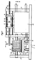
- the composting unit 1 of the composting machine according to the invention comprises a chassis composed of a base plate 2 on which three flanges 3, 4 and 5 are fixed, mutually parallel and orthogonal to the base plate 2.
- knobs 6 Between the flanges 3 and 4 is mounted a plurality of knobs 6 provided with characters 6a at their periphery and which can rotate independently. ment of each other around a common axis 7, bearing at its ends on said flanges 3 and 4.
- a printing anvil 8 Next to the knobs 6 is provided a printing anvil 8 supported by jacks 9, allowing it to come into contact with said wheels and move away from them.
- the jacks 9 are controlled for a solenoid valve 10 and are supported by the base plate 2.
- On the anvil 8 rests a printing support 11, which runs continuously. In FIG. 1, it has been assumed that the printing medium 11 was seen in cross section and that it was running orthogonally to the plane of the drawing.
- this printing medium 11 which is not necessarily a band but may be a cable, wire, etc. could just as easily be in the plane of the figure and scroll on the anvil of printing 8 from left to right or from right to left, possibly providing adequate passages in the flanges 3, 4 and 5.
- a solenoid 12, integral with the chassis 2, 3, 4, 5, is likely to actuate a blocking bar 13, to immobilize the rollers 6 during the printing operations.
- the carriage 15 Between the flanges 4 and 5 are provided guide rails 14 on which a carriage 15 can slide in both directions.
- the rails 14 are parallel to each other and to the axis 7 of the knurls 6.
- the carriage 15 carries two motors step by step 16 and 17 mounted in line, parallel to the rails 14 and to the axis 7.
- the axis 18 of the motor 16 is extended by a threaded part 19 engaged in the corresponding threading of a threaded hole 20 in the flange 5, which thus forms a nut.
- the axis 21 of the motor 17 freely crosses the flange 4 and is provided at its free end with a control wheel 22 which is integral in rotation.
- the plane of the control wheel 22 is parallel to those of the wheels 6 and said control wheel 22 can be brought into contact with each of said wheels.
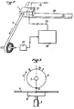
- the solenoid valve 10 for controlling the cylinders 9, the solenoid 12 for controlling the locking bar 13 and the motors 16 and 17 are supplied by a device 23, which forms an interface for a computer 24 (see also FIG. 2 in which the 'compacting unit 1 is shown in the form of a box through which the support 11) to which it is connected by a link 25.
- the device 23 may have other links 26 for the input and output of different information.
- the marking code being thus composed and the printing medium 11 scrolling on the printing anvil 8, at each instant when it is desired to mark the support 11, it suffices to send an order to the device 23, either directly by the connections 26, either via the computer 24 and the connection 25, so that the said device 23 actuates the jacks 9 through the solenoid valve 10 so that the printing anvil 8 presses the support 11 against the characters 6a of the dials 6 in the printing position.
- the computer 24 receives from a tachometer generator 27 information on the running speed of the printing medium 11 and deduces therefrom time intervals for controlling the solenoid valve 10, suitable for obtaining on the medium 11 remote code markings of any desired length. It will also be noted that between successive prints or markings on the print medium 11, the composting unit 1 may possibly totally or partially modify the printed code.
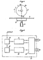
- the computer 24 is programmed so that the adjustment of each dial 6 by the stepping motor 17 and the control wheel 22 s 'performs as illustrated schematically in Figures 3 and 4. It is assumed that the characters 6a grow, from an origin O, in the direction F of clockwise rotation and that the number of steps of the motor 17 to rotate a dial 6 by half a turn is equal to N.
- N the number of steps of the motor 17 to rotate a dial 6 by half a turn is equal to N.
- FIG. 2 shows the composting unit 1 carried at the end of an elongated support arm 28, which can be very long, the connection 25 to the computer 24 can also be very long. Also, the link 25 is preferably of the type with series transmission of the logic levels 0 and 1, so that provision is made for parallel-series and series-parallel transformation devices in the device 23 and the computer 24.
- the device 23 comprises, in addition to interface 29 itself comprising the devices corresponding parallel-serial conversion and parallel-serial two loop control current asyn- - chrons 30 and 31, each of the serial type, arranged in parallel with each other.
- the loop 30, which corresponds to the operating modes of the entire composting machine, works only on reception and is associated with a decoder 32 to decode the information received by the links 26 to external information generators and by the link 25 to the computer 24.
- the functions of the loop 30 can be, among other things, the validation of the parameters of the composting machine such as support fault 11, end of cycle etc ... validation of the length of the support 11 to be printed, the validation of the number of supports 11 to be printed, the validation of the commands of the motors 16 and 17, the validation of the initialization and of the movements to the right or to the left of the motors 16 and 17, the validation of the starting and stopping the composting machine, etc ...
- the loop 30 plays the role of the control device for the control device 23.
- the loop 31 operates in transmission and reception and makes it possible to transmit to the computer 24 all the parameters relating to the composting machine, previously addressed by the loop 30 (generation of the functions) or to receive from the computer 24 the various data necessary for operation. of the composting machine (length and number of the support (s) 11 to be printed, etc.) and the control of the two stepper motors 16 and 17.
- the information received by the loop 31 is routed, for example in the device 33, by the functions generated by the loop 30. They become, depending on their destination, a length of print medium 11, a number of medium 11, numbers of steps for motors 16 and 17, initialization signals from said motors, machine starts or stops, etc.
- the information sent by loop 31 relates for example to the end of a printing cycle, the lack of support , etc ...
Landscapes
- Fertilizers (AREA)
- Printers Characterized By Their Purpose (AREA)
Applications Claiming Priority (2)
| Application Number | Priority Date | Filing Date | Title |
|---|---|---|---|
| FR8205103A FR2523901A1 (fr) | 1982-03-25 | 1982-03-25 | Machine de compostage automatisee et unite de compostage pour une telle machine |
| FR8205103 | 1982-03-25 |
Publications (2)
| Publication Number | Publication Date |
|---|---|
| EP0090706A1 EP0090706A1 (fr) | 1983-10-05 |
| EP0090706B1 true EP0090706B1 (fr) | 1985-06-05 |
Family
ID=9272393
Family Applications (1)
| Application Number | Title | Priority Date | Filing Date |
|---|---|---|---|
| EP83400551A Expired EP0090706B1 (fr) | 1982-03-25 | 1983-03-16 | Machine de compostage automatisée et unité de compostage pour une telle machine |
Country Status (6)
| Country | Link |
|---|---|
| US (1) | US4485735A (enExample) |
| EP (1) | EP0090706B1 (enExample) |
| JP (1) | JPS58177382A (enExample) |
| DE (1) | DE3360239D1 (enExample) |
| ES (1) | ES8404917A1 (enExample) |
| FR (1) | FR2523901A1 (enExample) |
Families Citing this family (15)
| Publication number | Priority date | Publication date | Assignee | Title |
|---|---|---|---|---|
| US4608923A (en) * | 1984-10-04 | 1986-09-02 | Pitney Bowes Inc. | Postal meter value selector sequencing system |
| US4628812A (en) * | 1984-10-19 | 1986-12-16 | Fisk James C | Variable data imprinter for credit cards and the like |
| FR2572827B1 (fr) * | 1984-11-05 | 1986-12-26 | Etude Const App Precision | Dispositif de positionnement angulaire automatique d'une pluralite d'organes rotatifs indexables de machine, et machine, notamment machine d'affranchissement postal comportant un tel dispositif |
| EP0259372A1 (en) * | 1986-02-26 | 1988-03-16 | Microtek Avon Limited | Identification printing apparatus |
| FR2610447B1 (fr) * | 1987-01-29 | 1990-05-25 | Peugeot | Dispositif de marquage de fils electriques |
| US4852482A (en) * | 1987-12-21 | 1989-08-01 | Pitney Bowes Inc. | Automatic printwheel setting system |
| US5343605A (en) * | 1991-09-26 | 1994-09-06 | Eubanks Engineering Company | Wire marking, cutting and stripping apparatus and method |
| US5279219A (en) * | 1992-11-25 | 1994-01-18 | Eubanks Engineering Co. | Marking apparatus |
| US5460086A (en) * | 1993-03-11 | 1995-10-24 | Bernardo; Joseph A. | Zip code to postnet conversion printing device |
| US6675458B1 (en) * | 2001-11-02 | 2004-01-13 | Ciena Corporation | Fiber optic cable stripping and measurement apparatus |
| ES2719146T3 (es) † | 2006-06-23 | 2019-07-08 | Kba Notasys Sa | Dispositivo de numeración para numeración tipográfica que tiene detectores de calibración |
| DE102011008859B3 (de) * | 2011-01-18 | 2012-06-06 | Paul Leibinger Gmbh & Co. Kg | Nummerierwerk |
| EP3047978A1 (en) * | 2015-01-23 | 2016-07-27 | KIG, podjetje za proizvodnjo in upravijanje druzb, d.d. | Mechanical press for printing or impressing symbols on a substrate |
| CN111332043B (zh) * | 2020-04-07 | 2024-06-11 | 佛山华远智能装备有限责任公司 | 一种车牌全自动压字机 |
| WO2025093084A1 (de) * | 2023-10-30 | 2025-05-08 | Zeiser Gmbh | Vorrichtung zum einstellen von nummerierwerken auf einen konkreten wert einer durch ein nummerierwerk aufzudruckenden zeichenfolge |
Family Cites Families (11)
| Publication number | Priority date | Publication date | Assignee | Title |
|---|---|---|---|---|
| BE630304A (enExample) * | 1962-03-30 | |||
| DE2039535C2 (de) * | 1970-08-08 | 1982-11-04 | Nixdorf Computer Ag, 4790 Paderborn | Einrichtung zur Steuerung der elektromechanischen Positionierung des Typenträgers eines seriellen Schreibwerks |
| US3931614A (en) * | 1973-06-26 | 1976-01-06 | Addressograph Multigraph Corporation | Data terminal having improved data output presentation |
| JPS5097417A (enExample) * | 1973-12-28 | 1975-08-02 | ||
| US3916785A (en) * | 1974-06-03 | 1975-11-04 | Ncr Co | Imprinting means for a computer access terminal |
| US4050374A (en) * | 1976-06-21 | 1977-09-27 | Pitney-Bowes, Inc. | Meter setting mechanism |
| US4127064A (en) * | 1977-03-14 | 1978-11-28 | Hi-Speed Checkweigher Co., Inc. | Large type rotary printer |
| JPS5473816U (enExample) * | 1977-11-04 | 1979-05-25 | ||
| GB2018684B (en) * | 1978-01-20 | 1982-03-31 | Mccorquodale Machine Systens L | Printing apparatus |
| US4357115A (en) * | 1979-01-02 | 1982-11-02 | Or Michael C P | Printing system for multiple character languages and elements thereof |
| DE3030139C2 (de) * | 1980-08-08 | 1983-10-06 | Esselte Pendaflex Corp., 11530 Garden City, N.Y. | Handetikettiergerät |
-
1982
- 1982-03-25 FR FR8205103A patent/FR2523901A1/fr active Granted
-
1983
- 1983-03-16 EP EP83400551A patent/EP0090706B1/fr not_active Expired
- 1983-03-16 DE DE8383400551T patent/DE3360239D1/de not_active Expired
- 1983-03-22 US US06/477,629 patent/US4485735A/en not_active Expired - Lifetime
- 1983-03-25 JP JP58051371A patent/JPS58177382A/ja active Granted
- 1983-03-25 ES ES521355A patent/ES8404917A1/es not_active Expired
Also Published As
| Publication number | Publication date |
|---|---|
| FR2523901A1 (fr) | 1983-09-30 |
| JPS58177382A (ja) | 1983-10-18 |
| ES521355A0 (es) | 1984-05-16 |
| EP0090706A1 (fr) | 1983-10-05 |
| ES8404917A1 (es) | 1984-05-16 |
| US4485735A (en) | 1984-12-04 |
| JPH0337513B2 (enExample) | 1991-06-05 |
| DE3360239D1 (en) | 1985-07-11 |
| FR2523901B1 (enExample) | 1985-05-17 |
Similar Documents
| Publication | Publication Date | Title |
|---|---|---|
| EP0090706B1 (fr) | Machine de compostage automatisée et unité de compostage pour une telle machine | |
| EP0099778A1 (fr) | Porte-cibles à balayage mécanique | |
| EP0319530A1 (fr) | Dispositif d'enregistrement magnetique ou autre a une ou plusieurs tetes graveuses tournantes. | |
| EP2236296A1 (fr) | Machine et procédé de marquage ou d'étiquetage | |
| CH639584A5 (fr) | Automate susceptible d'apprentissage. | |
| CA2024415C (fr) | Dispositif pour sertir des elements de connexion sur des conducteurs electriques et systeme de sertissage automatique comportant un tel dispositif | |
| EP0181804B1 (fr) | Dispositif de positionnement angulaire automatique d'une pluralité d'organes rotatifs indexables de machine, et machine, notamment machine d'affranchissement postal, comportant un tel dispositif | |
| FR2472973A1 (fr) | Machine a ecrire electronique | |
| EP0013294B1 (fr) | Ensemble d'impression à roues multiples à languettes porte-caractères pour machine à écrire ou imprimante | |
| EP0432833A1 (fr) | Distributeur de gouttes de verre fondu dans les machines pour la réalisation d'objets creux en verre | |
| FR2468685A1 (fr) | Machine pour la fabrication des cables a torons entrelaces | |
| CA1199393A (fr) | Machine de compostage automatisee et unite de compostage pour une telle machine | |
| EP3150754B1 (fr) | Système de contrôle d'une mécanique jacquard, mécanique jacquard et métier à tisser équipés d'un tel système | |
| EP2289654B1 (fr) | Dispositif d'indexation et d'entraînement des broches d'un tour multibroches | |
| EP0930551B1 (fr) | Procédé de pilotage de déposé de mèches par enroulement ou au contact sur des structures de grandes dimensions et machine pour sa mise en oeuvre | |
| EP3427006B1 (fr) | Dispositif de contrôle tridimensionnel sans contact d'une pièce creuse à surface interne de révolution et procédé correspondant | |
| EP0554136A1 (fr) | Dispositif pou l'identification d'un conducteur électrique | |
| EP0014119A1 (fr) | Positionnement de microcomposants, notamment pour les circuits à couches épaisses ou à couches minces | |
| EP0604317A1 (fr) | Dispositif de réglage des molettes d'impression dans une machine à affranchir | |
| FR2742772A1 (fr) | Machine de tressage | |
| FR2685114A1 (fr) | Machine a affranchir comprenant un tambour d'impression rotatif. | |
| FR2661855A1 (fr) | Dispositif pour le remplacement automatique d'outils dans un magasin d'outils. | |
| FR2610447A1 (fr) | Dispositif de marquage de fils electriques | |
| EP1733867A1 (fr) | Dispositif de pose de fil de renforcement | |
| EP0074902A1 (fr) | Procédé et circuit pour la réalisation d'un support impressionné et pour la commande d'un automate |
Legal Events
| Date | Code | Title | Description |
|---|---|---|---|
| PUAI | Public reference made under article 153(3) epc to a published international application that has entered the european phase |
Free format text: ORIGINAL CODE: 0009012 |
|
| AK | Designated contracting states |
Kind code of ref document: A1 Designated state(s): BE CH DE GB IT LI NL SE Designated state(s): BE CH DE GB IT LI NL SE |
|
| 17P | Request for examination filed |
Effective date: 19830914 |
|
| ITF | It: translation for a ep patent filed | ||
| GRAA | (expected) grant |
Free format text: ORIGINAL CODE: 0009210 |
|
| AK | Designated contracting states |
Kind code of ref document: B1 Designated state(s): BE CH DE GB IT LI NL SE Designated state(s): BE CH DE GB IT LI NL SE |
|
| REF | Corresponds to: |
Ref document number: 3360239 Country of ref document: DE Date of ref document: 19850711 |
|
| PLBE | No opposition filed within time limit |
Free format text: ORIGINAL CODE: 0009261 |
|
| STAA | Information on the status of an ep patent application or granted ep patent |
Free format text: STATUS: NO OPPOSITION FILED WITHIN TIME LIMIT |
|
| 26N | No opposition filed | ||
| NLT1 | Nl: modifications of names registered in virtue of documents presented to the patent office pursuant to art. 16 a, paragraph 1 |
Owner name: AEROSPATIALE SOCIETE NATIONALE INDUSTRIELLE TE PAR |
|
| ITTA | It: last paid annual fee | ||
| EAL | Se: european patent in force in sweden |
Ref document number: 83400551.4 |
|
| REG | Reference to a national code |
Ref country code: GB Ref legal event code: IF02 |
|
| PGFP | Annual fee paid to national office [announced via postgrant information from national office to epo] |
Ref country code: CH Payment date: 20020213 Year of fee payment: 20 |
|
| PGFP | Annual fee paid to national office [announced via postgrant information from national office to epo] |
Ref country code: SE Payment date: 20020225 Year of fee payment: 20 |
|
| PGFP | Annual fee paid to national office [announced via postgrant information from national office to epo] |
Ref country code: DE Payment date: 20020228 Year of fee payment: 20 |
|
| PGFP | Annual fee paid to national office [announced via postgrant information from national office to epo] |
Ref country code: BE Payment date: 20020301 Year of fee payment: 20 |
|
| PGFP | Annual fee paid to national office [announced via postgrant information from national office to epo] |
Ref country code: GB Payment date: 20020305 Year of fee payment: 20 |
|
| PGFP | Annual fee paid to national office [announced via postgrant information from national office to epo] |
Ref country code: NL Payment date: 20020329 Year of fee payment: 20 |
|
| PG25 | Lapsed in a contracting state [announced via postgrant information from national office to epo] |
Ref country code: LI Free format text: LAPSE BECAUSE OF EXPIRATION OF PROTECTION Effective date: 20030315 Ref country code: GB Free format text: LAPSE BECAUSE OF EXPIRATION OF PROTECTION Effective date: 20030315 Ref country code: CH Free format text: LAPSE BECAUSE OF EXPIRATION OF PROTECTION Effective date: 20030315 |
|
| PG25 | Lapsed in a contracting state [announced via postgrant information from national office to epo] |
Ref country code: NL Free format text: LAPSE BECAUSE OF EXPIRATION OF PROTECTION Effective date: 20030316 |
|
| BE20 | Be: patent expired |
Owner name: *SOC. NATIONALE INDUSTRIELLE *AEROSPATIALE Effective date: 20030316 |
|
| REG | Reference to a national code |
Ref country code: GB Ref legal event code: PE20 |
|
| REG | Reference to a national code |
Ref country code: CH Ref legal event code: PL |
|
| NLV7 | Nl: ceased due to reaching the maximum lifetime of a patent |
Effective date: 20030316 |
|
| EUG | Se: european patent has lapsed |