EP0090706B1 - Automatic stamping machine and stamping unit for such a machine - Google Patents
Automatic stamping machine and stamping unit for such a machine Download PDFInfo
- Publication number
- EP0090706B1 EP0090706B1 EP83400551A EP83400551A EP0090706B1 EP 0090706 B1 EP0090706 B1 EP 0090706B1 EP 83400551 A EP83400551 A EP 83400551A EP 83400551 A EP83400551 A EP 83400551A EP 0090706 B1 EP0090706 B1 EP 0090706B1
- Authority
- EP
- European Patent Office
- Prior art keywords
- printing
- wheel
- wheels
- motor
- steps
- Prior art date
- Legal status (The legal status is an assumption and is not a legal conclusion. Google has not performed a legal analysis and makes no representation as to the accuracy of the status listed.)
- Expired
Links
Images
Classifications
-
- B—PERFORMING OPERATIONS; TRANSPORTING
- B41—PRINTING; LINING MACHINES; TYPEWRITERS; STAMPS
- B41F—PRINTING MACHINES OR PRESSES
- B41F17/00—Printing apparatus or machines of special types or for particular purposes, not otherwise provided for
- B41F17/008—Numbering devices for printing on articles other than sheets or webs
-
- B—PERFORMING OPERATIONS; TRANSPORTING
- B41—PRINTING; LINING MACHINES; TYPEWRITERS; STAMPS
- B41F—PRINTING MACHINES OR PRESSES
- B41F33/00—Indicating, counting, warning, control or safety devices
- B41F33/009—Devices for controlling numbering
-
- B—PERFORMING OPERATIONS; TRANSPORTING
- B41—PRINTING; LINING MACHINES; TYPEWRITERS; STAMPS
- B41K—STAMPS; STAMPING OR NUMBERING APPARATUS OR DEVICES
- B41K3/00—Apparatus for stamping articles having integral means for supporting the articles to be stamped
- B41K3/02—Apparatus for stamping articles having integral means for supporting the articles to be stamped with stamping surface located above article-supporting surface
- B41K3/04—Apparatus for stamping articles having integral means for supporting the articles to be stamped with stamping surface located above article-supporting surface and movable at right angles to the surface to be stamped
- B41K3/10—Apparatus for stamping articles having integral means for supporting the articles to be stamped with stamping surface located above article-supporting surface and movable at right angles to the surface to be stamped having automatic means for changing type-characters, e.g. numbering devices
- B41K3/102—Numbering devices
Description
La présente invention concerne une machine de compostage automatisée permettant l'impression d'un code d'identification sur tout support, et notamment sur des pièces mécaniques ou des câbles électriques.The present invention relates to an automated composting machine allowing the printing of an identification code on any medium, and in particular on mechanical parts or electric cables.
On sait que les méthodes modernes de gestion, de fabrication, d'assemblage, de montage, de maintenance, etc... rendent indispensable l'identification des pièces ou des éléments fabriqués pour les différencier les uns des autres. Une telle opération de marquage, qui tend à être généralisée, forme un poste de travail important, par exemple en aéronautique où les câblages électriques constituent souvent des masses importantes de conducteurs de faible diamètre.We know that modern methods of management, manufacturing, assembly, mounting, maintenance, etc. make it essential to identify the parts or elements manufactured to differentiate them from each other. Such a marking operation, which tends to be generalized, forms an important work station, for example in aeronautics where the electrical cables often constitute large masses of conductors of small diameter.
Pour réaliser un tel marquage d'identification, on connaît de nombreuses machines.Many machines are known for making such identification marking.
Tout d'abord, il existe des machines manuelles à molettes. Par exemple, le brevet US-A-3 572 239 décrit une machine de compostage pourvue d'une tête d'impression comportant une pluralité de molettes rotatives coaxiales, disposées côte à côte et munies de caractères d'impression, et une roue de commande desdites molettes ayant son axe parallèle à celui de ces dernières et pouvant, d'une part, se déplacer parallèlement à l'axe desdites molettes pour venir en contact ou en prise avec l'une quelconque desdites molettes choisie parmi les autres et, d'autre part, tourner autour de son axe pour pouvoir entraîner en rotation ladite molette choisie et amener en position d'impression un caractère désiré de cette dernière. Dans cette machine connue, le mouvement de translation et le mouvement de rotation de la roue de commande sont commandés au moyen de boutons moletés actionnés manuellement, de sorte que le réglage de l'ensemble des molettes et le blocage de celles-ci dans les- positions choisies est long et fastidieux. Il en est d'autant plus ainsi que, dans ce type de machine, il est souvent nécessaire de déplacer la tête d'impression, pour accéder au mécanisme de réglage des molettes, à chaque fois que l'on désire modifier le code de compostage. Ces inconvénients s'accompagnent d'un risque d'erreurs élevé lorsque le changement de compostage devient fréquent, car il s'avère fatigant pour les yeux des opérateurs. En outre, une telle machine n'est pas compatible avec un système informatisé, comme l'exigent en général les fabrications actuelles, ce qui pénalise fortement la production.First, there are manual wheel machines. For example, patent US Pat. No. 3,572,239 describes a composting machine provided with a printing head comprising a plurality of coaxial rotary rollers, arranged side by side and provided with printing characters, and a control wheel. said knurls having its axis parallel to that of the latter and being able, on the one hand, to move parallel to the axis of said knurls to come into contact or engagement with any one of said knurls chosen from among the others and, on the other hand, rotate around its axis in order to be able to drive said selected wheel in rotation and bring the desired character of the latter to the printing position. In this known machine, the translational movement and the rotational movement of the control wheel are controlled by means of knurled buttons actuated manually, so that the adjustment of the set of rollers and the locking of these in the- chosen positions is long and tedious. This is all the more so since, in this type of machine, it is often necessary to move the print head, in order to access the adjustment mechanism of the rollers, each time that it is desired to modify the composting code. . These drawbacks are accompanied by a high risk of errors when the change of composting becomes frequent, because it is tiring for the eyes of operators. In addition, such a machine is not compatible with a computerized system, as generally required by current manufacturing, which greatly penalizes production.
On connaît par ailleurs des machines de compostage permettant un compostage automatisé.Composting machines are also known which allow automated composting.
Par exemple, le brevet US-A-3 868 638 décrit une machine, gérée par un calculateur et comportant, d'une part, un tambour d'impression rotatif portant une pluralité de caractères agencés selon les génératrices et les parallèles dudit tambour et, d'autre part, une pluralité de marteaux d'impression juxtaposés définissant une ligne d'impression. Une telle machine présente l'inconvénient d'être mécaniquement compliquée et lourde. De plus, elle nécessite l'utilisation des comparateurs pour déterminer les caractères à imprimer.For example, US Pat. No. 3,868,638 describes a machine, managed by a computer and comprising, on the one hand, a rotary printing drum carrying a plurality of characters arranged according to the generatrices and the parallels of said drum and, on the other hand, a plurality of juxtaposed printing hammers defining a printing line. Such a machine has the disadvantage of being mechanically complicated and heavy. In addition, it requires the use of comparators to determine the characters to be printed.
Dans la machine de compostage automatisée décrite dans le document GB-A-2 018 684 à chaque molette est associée un moteur pas à pas en vue de l'entraîner à la position d'impression souhaitée.In the automated composting machine described in document GB-A-2,018,684, each wheel is associated with a stepping motor in order to drive it to the desired printing position.
Une autre machine de compostage automatisée connue permet la suppression de la pluralité des marteaux d'impression de la machine du brevet US-A-3 868 638 en utilisant une pluralité de molettes à la place du tambour d'impression. Cependant, cette autre machine connue doit également être équipée d'encodeurs de position ou de comparateurs, couplés avec le calculateur. Ces comparateurs informent l'automatisme de commande sur la position occupée par les molettes d'impression et agissent sur celles-ci au moyen de crémaillères. L'opération de réglage du compostage se scinde en deux phases :
- - la remise à zéro du composteur, obtenue en remontant les crémaillères à leur point le plus haut ;
- - le réglage qui s'effectue pendant la descente des crémaillères. A chaque molette d'impression correspond une desdites crémaillères commandée par un moteur au moyen d'une bielle qui communique à l'ensemble des crémaillères un mouvement montant et descendant. Un encodeur disposé sur l'axe de la bielle de commande indique au calculateur la position des caractères au fur et à mesure du mouvement. Dès que la position d'une molette correspond au caractère demandé pour celle-ci, la crémaillère associée peut être bloquée mécaniquement dans sa course descendante par un cliquet mû par un solénoïde. Les molettes sont ainsi successivement positionnées pour former le code à marquer.
- - resetting of the composter, obtained by raising the racks to their highest point;
- - the adjustment which takes place during the descent of the racks. Each printing wheel corresponds to one of said racks controlled by a motor by means of a connecting rod which communicates to all the racks an up and down movement. An encoder placed on the axis of the control rod indicates to the computer the position of the characters as the movement progresses. As soon as the position of a wheel corresponds to the character requested for it, the associated rack can be mechanically locked in its downward travel by a pawl driven by a solenoid. The knobs are thus successively positioned to form the code to be marked.
Un autre document FR-A-2 355 659 décrit une machine de compostage automatisée comportant des rangées d'impression qui peuvent être réglées dans différentes positions au moyen d'un ensemble d'engrenages comprenant un certain nombre de pignons espacés latéralement, montés indépendamment à rotation et entraînés à l'aide de deux moteurs pas à pas.Another document FR-A-2 355 659 describes an automated composting machine comprising printing rows which can be adjusted in different positions by means of a set of gears comprising a number of laterally spaced pinions, independently mounted at rotation and driven by two stepper motors.
Ainsi, ces machines de compostage automatisées connues sont lourdes et volumineuses. Leur mécanique est complexe et difficile à mettre au point. En outre, la délicatesse de leur réglage ne permet pas de les manipuler dans l'espace pour les utiliser dans une configuration ou une position autre que celle de la mise au point, ce qui en limite beaucoup l'utilisation.Thus, these known automated composting machines are heavy and bulky. Their mechanics are complex and difficult to develop. In addition, the delicacy of their adjustment does not allow them to be manipulated in space to use them in a configuration or position other than that of focusing, which greatly limits their use.
La présente invention a pour objet une machine de compostage automatisée mécaniquement très simplifiée pouvant être utilisée dans toute position de travail désirée, par exemple en porte-à- faux au bout d'un bras de support, et pilotée de façon très simple, tout en ayant un réglage très rapide et optimisé.The present invention relates to a very simplified mechanically automated composting machine which can be used in any desired working position, for example door-to-door false at the end of a support arm, and controlled very simply, while having a very fast and optimized adjustment.
A cette fin, selon l'invention, la machine de compostage pourvue d'une tête d'impression comportant une pluralité de molettes rotatives coaxiales, disposées côte à côte et munies de caractères d'impression, et une roue de commande desdites molettes ayant son axe parallèle à celui de ces dernières et pouvant, d'une part, se déplacer parallèlement à l'axe desdites molettes pour venir en contact ou en prise avec l'une quelconque desdites molettes choisie parmi les autres et, d'autre part, tourner autour de son axe pour pouvoir entraîner en rotation ladite molette choisie et amener en position d'impression un caractère désiré de cette dernière, est remarquable en ce que ladite roue de commande est solidaire en translation d'un coulisseau mobile parallèlement à l'axe desdites molettes et portant deux moteurs pas-à-pas, dont le premier permet le coulissement dudit coulisseau et le second entraîne en rotation ladite roue de commande et en ce qu'est prévu un dispositif de commande desdits moteurs pas-à-pas comportant des moyens à mémoire emmagasinant pour chaque molette le nombre de pas du second moteur, mesuré par rapport à une origine de rotation de la molette, correspondant au caractère de la molette actuellement en position d'impression, des moyens d'affichage de données permettant d'indiquer, pour chaque molette, le nombre de pas du second moteur, mesuré par . rapport à ladite origine, correspondant à un caractère de la molette que l'on désire amener maintenant en position d'impression, des moyens de calcul permettant de faire pour chaque molette la différence entre le nombre de pas emmagasiné et le nombre de pas affiché, des moyens d'alimentation commandés du premier moteur pour amener successivement la roue de commande en regard de chaque molette et des moyens d'alimentation commandés du second moteur pour faire tourner chaque molette d'un nombre de pas égal à la différence correspondante, lorsque la roue d'entraînement se trouve en regard de cette molette.To this end, according to the invention, the composting machine provided with a printing head comprising a plurality of coaxial rotary rollers, arranged side by side and provided with printing characters, and a control wheel of said rollers having its axis parallel to that of the latter and able, on the one hand, to move parallel to the axis of said knobs to come into contact or engagement with any one of said knobs chosen from among the others and, on the other hand, to rotate around its axis in order to be able to drive said selected wheel in rotation and bring a desired character of the latter in the printing position, is remarkable in that said control wheel is integral in translation with a movable slide parallel to the axis of said wheels and carrying two stepping motors, the first of which allows the sliding of said slide and the second drives said control wheel in rotation and in what is provided a device for controlling said motes step by step urs comprising memory means storing for each wheel the number of steps of the second motor, measured with respect to an origin of rotation of the wheel, corresponding to the character of the wheel currently in the printing position, means display of data making it possible to indicate, for each wheel, the number of steps of the second motor, measured by. with respect to said origin, corresponding to a character of the wheel which it is desired to bring now to the printing position, calculation means making it possible to make for each wheel the difference between the number of steps stored and the number of steps displayed, supply means controlled from the first motor to successively bring the control wheel opposite each wheel and supply means controlled from the second motor to rotate each wheel by a number of steps equal to the corresponding difference, when the drive wheel is located next to this wheel.
On voit ainsi que la partie mécanique de la machine selon l'invention est particulièrement simple, puisqu'elle ne nécessite ni comparateurs, ni encodeurs de position. Elle peut former un ensemble compact dans lequel les molettes et le coulisseau, pourvu des deux moteurs pas-à-pas et de la roue de commande, sont montés sur un châssis commun. Dans cet ensemble mécanique, le mouvement de coulissement du coulisseau peut s'effectuer quelle que soit la position du châssis, de sorte que ledit ensemble peut occuper toute position de travail appropriée.It can thus be seen that the mechanical part of the machine according to the invention is particularly simple, since it requires neither comparators nor position encoders. It can form a compact assembly in which the rollers and the slide, provided with the two stepping motors and the control wheel, are mounted on a common chassis. In this mechanical assembly, the sliding movement of the slide can take place regardless of the position of the chassis, so that said assembly can occupy any suitable working position.
Dans un mode de réalisation avantageux, lesdits moyens à mémoire, lesdits moyens d'introduction ou d'affichage de données, et lesdits moyens de calcul sont regroupés dans un calculateur, ou forment un appareil périphérique d'un tel calculateur, tandis que les moyens d'alimentation commandés des deux moteurs pas-à-pas sont associés à un dispositif d'interface et sont montés, avec celui-ci, solidaires dudit ensemble mécanique, une liaison par câble, par exemple du type à transmission en série, étant prévue entre ledit calculateur et ledit dispositif d'interface. Ainsi, l'ensemble mécanique et le dispositif d'interface forment une unité de compostage légère et peu encombrante pouvant être disposée en tout endroit désiré et approprié d'une machine complexe de fabrication, puisque la liaison série permet de séparer physiquement (mais non pas électriquement) ladite unité du calculateur. Vis-à- vis de celui-ci, une telle unité de compostage se comporte comme un simple appareil périphérique (ou terminal).In an advantageous embodiment, said memory means, said data input or display means, and said calculation means are grouped in a computer, or form a peripheral device of such a computer, while the means controlled supply of the two stepping motors are associated with an interface device and are mounted therewith, integral with said mechanical assembly, a cable connection, for example of the type with serial transmission, being provided between said computer and said interface device. Thus, the mechanical assembly and the interface device form a light and space-saving composting unit which can be placed in any desired and appropriate location of a complex manufacturing machine, since the serial link makes it possible to physically separate (but not electrically) said unit of the computer. With regard to this, such a composting unit behaves like a simple peripheral (or terminal) device.
On remarquera par ailleurs que, lors du changement de réglage des molettes, grâce à la structure prévue par l'invention, il n'est pas nécessaire de ramener systématiquement les molettes à leur origine puisque la modification de réglage a lieu par différence. Le changement de code de compostage est donc particulièrement rapide.Note also that, when changing the setting of the knobs, thanks to the structure provided by the invention, it is not necessary to systematically return the knobs to their origin since the change in setting takes place by difference. Changing the composting code is therefore particularly quick.
Pour augmenter encore la rapidité d'un changement de code, il est de plus prévu, d'une part que ledit second moteur est du type pouvant tourner dans les deux sens de rotation, et, d'autre part, que lesdits moyens de calcul sont associés à des moyens de comparaison de la différence des nombres de pas délivrée par lesdits moyens de calcul au nombre de pas de moteur correspondant à une rotation de 180° des molettes, le résultat de ladite comparaison étant utilisé pour amener en position d'impression le caractère maintenant désiré par la rotation d'amplitude angulaire la plus petite.To further increase the speed of a code change, it is further provided, on the one hand that said second motor is of the type that can rotate in both directions of rotation, and, on the other hand, that said means of calculation are associated with means for comparing the difference in the number of steps delivered by said calculation means to the number of motor steps corresponding to a 180 ° rotation of the wheels, the result of said comparison being used to bring the printing position the character now desired by the smallest angular amplitude rotation.
De préférence, les moyens d'alimentation commandés des moteurs pas-à-pas font partie de deux boucles asynchrones de courant, l'une desdites boucles concernant les modes de fonctionnement de la machine et l'autre la commande des différents actuateurs de ladite machine.Preferably, the supply means controlled by the stepping motors are part of two asynchronous current loops, one of said loops relating to the operating modes of the machine and the other the control of the various actuators of said machine. .
Les figures du dessin annexé feront bien comprendre comment l'invention peut être réalisée.
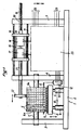
- La figure 1 montre l'unité de compostage de la machine de compostage selon l'invention.
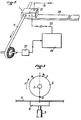
- La figure 2 est une vue schématique d'ensemble de la machine de compostage selon l'invention.
- Les figures 3 et 4 illustrent le processus de réglage des molettes.
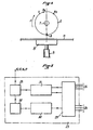
- La figure 5 donne le schéma synoptique du dispositif d'interface.
- Figure 1 shows the composting unit of the composting machine according to the invention.
- Figure 2 is a schematic overview of the composting machine according to the invention.
- Figures 3 and 4 illustrate the dial adjustment process.
- Figure 5 gives the block diagram of the interface device.
Sur ces figures des références identiques désignent des éléments semblables.In these figures, identical references designate similar elements.
L'unité de compostage 1 de la machine de compostage selon l'invention comporte un châssis composé d'une plaque de base 2 sur laquelle sont fixés trois flasques 3, 4 et 5, parallèles entre eux et orthogonaux à la plaque de base 2.The composting unit 1 of the composting machine according to the invention comprises a chassis composed of a
Entre les flasques 3 et 4 est montée une pluralité de molettes 6 pourvues de caractères 6a à leur périphérie et pouvant tourner indépendamment l'une de l'autre autour d'un axe commun 7, prenant appui à ses extrémités sur lesdits flasques 3 et 4. En regard des molettes 6 est prévue une enclume d'impression 8 supportée par des vérins 9, lui permettant de venir au contact desdites molettes et de s'en écarter. Les vérins 9 sont commandés pour une électrovanne 10 et sont supportés par la plaque de base 2. Sur l'enclume 8 repose un support d'impression 11, qui défile en continu. Sur la figure 1, on a supposé que le support d'impression 11 était vu en coupe transversale et qu'il défilait orthogonalement au plan du dessin. Bien entendu, ce support d'impression 11, qui n'est pas forcément une bande mais peut être un câble, fil, etc... pourrait tout aussi bien se trouver dans le plan de la figure et défiler sur l'enclume d'impression 8 de la gauche vers la droite ou de la droite vers la gauche, en prévoyant éventuellement les passages adéquats dans les flasques 3, 4 et 5. Un solénoïde 12, solidaire du châssis 2, 3, 4, 5, est susceptible d'actionner une barre de blocage 13, pour immobiliser les molettes 6 pendant les opérations d'impression.Between the
Entre les flasques 4 et 5 sont prévus des rails de guidage 14 sur lesquels peut coulisser, dans les deux sens, un chariot 15. Les rails 14 sont parallèles entre eux et à l'axe 7 des molettes 6. Le chariot 15 porte deux moteurs pas-à-pas 16 et 17 montés en ligne, parallèlement aux rails 14 et à l'axe 7. L'axe 18 du motèur 16 est prolongé par une partie filetée 19 engagée dans le filetage correspondant d'un trou fileté 20 du flasque 5, qui forme ainsi écrou. L'axe 21 du moteur 17 traverse librement le flasque 4 et est pourvu à son extrémité libre d'une roue de commande 22 qui est est solidaire en rotation. Le plan de la roue de commande 22 est parallèle à ceux des molettes 6 et ladite roue de commande 22 peut être amenée au contact de chacune desdites molettes.Between the
L'électrovanne 10 de commande des vérins 9, le solénoïde 12 de commande de la barre de blocage 13 et les moteurs 16 et 17 sont alimentés par un dispositif 23, qui forme interface pour un calculateur 24 (voir également la figure 2 sur laquelle l'unité de compactage 1 est représentée sous la forme d'une boîte traversée par le support 11) auquel il est relié par une liaison 25. Le dispositif 23 peut présenter d'autres liaisons 26 pour l'entrée et la sortie de différentes informations.The
Lorsque l'on désire composer un code de marquage à l'aide des molettes 6, le calculateur 24 adresse, par la liaison 26, les ordres suivants à l'unité 1 :
- - désactivation (ou activation) du solénoïde 12
par le dispositif 23, de façon que la barre de blocage 13 libère les molettes 6 et que celles-ci puissent être tournées ; - - activation du moteur pas-à-
pas 16par le dispositif 23 pour qu'il fasse tournerson axe 18 et qu'en conséquence de la liaison filetée 19-20, l'ensemble du chariot 15 puisse coulisser le long des rails 14, de sorte que la roue de commande 22 puisse être amenée successivement au contact de chacune des molettes 6, par exemple en commençant par l'une des molettes d'extrémité. L'activation du moteur pas-à-pas est discontinue, n'intervenant que lors du passage de la roue de commande 22d'une molette 6 à la suivante, de façon que ladite roue de commande 22 reste en contact avec chacune desdites molettes 6 pendant un temps d'arrêt suffisant pour amener le caractère 6a désiré de celle-ci en position d'impression, c'est-à-dire en regard de l'enclume d'impression 8 ; - - activation du moteur pas-à-pas 17
par le dispositif 23 pendant lesdits temps d'arrêt du moteur 16, pour que, par suite de la liaison (friction, engrènement) entre la roue de commande 22 et la molette 6 correspondante le caractère 6a désiré soit amené en position d'impression ; - - activation (ou désactivation) du solénoïde 12
par le dispositif 23 pour, après réglage de toutes les molettes 6, bloquer celles-ci en position en vue de l'impression ; - - éventuellement, activation du moteur pas-à-
pas 16par le dispositif 23 pour ramener le chariot 15 à sa position initiale.
- - deactivation (or activation) of the
solenoid 12 by thedevice 23, so that the locking bar 13 releases theknobs 6 and that these can be rotated; - - activation of the stepping
motor 16 by thedevice 23 so that it rotates itsaxis 18 and that, as a consequence of the threaded connection 19-20, the whole of thecarriage 15 can slide along therails 14, so that thecontrol wheel 22 can be brought successively into contact with each of theknobs 6, for example starting with one of the end knobs. The activation of the stepping motor is discontinuous, occurring only during the passage of thecontrol wheel 22 from onewheel 6 to the next, so that saidcontrol wheel 22 remains in contact with each of saidwheels 6 during a sufficient stop time to bring the desiredcharacter 6a thereof into the printing position, that is to say facing theprinting anvil 8; - - activation of the stepping motor 17 by the
device 23 during said stopping times of themotor 16, so that, as a result of the connection (friction, meshing) between thecontrol wheel 22 and thecorresponding wheel 6 thecharacter 6a desired is brought to the printing position; - - Activation (or deactivation) of the
solenoid 12 by thedevice 23 for, after adjusting all theknobs 6, lock them in position for printing; - - Optionally, activation of the stepping
motor 16 by thedevice 23 to return thecarriage 15 to its initial position.
Le code de marquage étant ainsi composé et le support d'impression 11 défilant sur l'enclume d'impression 8, à chaque instant où l'on désire marquer le support 11, il suffit d'adresser un ordre au dispositif 23, soit directement par les liaisons 26, soit par l'intermédiaire du calculateur 24 et de la liaison 25, pour que ledit dispositif 23 actionne les vérins 9 à travers l'électrovanne 10 de façon que l'enclume d'impression 8 presse le support 11 contre les caractères 6a des molettes 6 en position d'impression.The marking code being thus composed and the
Par exemple, le calculateur 24 reçoit d'un générateur tachymétrique 27 des informations sur la vitesse de défilement du support d'impression 11 et il en déduit des intervalles de temps de commande de l'électrovanrre 10, propres à obtenir sur le support 11 des marquages du code distants de toute longueur désirée. On «remarquera d'ailleurs qu'entre des impressions ou marquages successifs sur le support d'impression 11, l'unité de compostage 1 peut éventuellement modifier totalement ou partiellement le code imprimé.For example, the
De préférence, afin que le passage d'un code à un autre soit le plus court possible, le calculateur 24 est programmé de façon que le réglage de chaque molette 6 par le moteur pas-à-pas 17 et la roue de commande 22 s'effectue de la façon illustrée schématiquement par les figures 3 et 4. On suppose que les caractères 6a croissent, à partir d'une origine O, dans le sens F de rotation des aiguilles d'une montre et que le nombre de pas du moteur 17 pour faire tourner une molette 6 d'un demi-tour est égal à N. On a représenté en A le caractère 6a en position d'impression que l'on désire changer et en B1, B2, B3 et B4 des caractères 6a que l'on désire amener en position d'impression (c'est-à-dire à la place du caractère (A).Preferably, so that the passage from one code to another is as short as possible, the
Le processus imposé par le calculateur 24 est le suivant :
- - si le nouveau caractère B1 à amener en position d'impression est plus grand que le caractère A actuellement en position d'impression et si la différence C1 = B1 - A, qui est positive, est inférieure ou égale à N, le moteur 17 est actionné dans le sens inverse des aiguilles d'une montre (sens inverse à F) d'un nombre de pas correspondant à C1.
- - si le nouveau caractère B2 à amener en position d'impression est plus grand que le caractère A et si la différence positive C2 = B2 - A est supérieure à N, le moteur 17 est actionné dans le sens des aiguilles d'une montre (sens F) d'un nombre de pas correspondant à 2N-C2 ;
- - si le nouveau caractère B3 à amener en position d'impression est plus petit que le caractère A et si la différence D1 = A - B3 est inférieure à N, le moteur 17 est actionné dans le sens des aiguilles d'une montre (sens F) d'un nombre de pas correspondant à D1 ;
- - si le nouveau caractère B4 à amener en position d'impression est plus petit que le caractère A et si la différence D2 = A - B4 est supérieure à N, le moteur 17 est actionné dans le sens inverse des aiguilles d'une montre (sens inverse de F) d'un nombre de pas correspondant à 2N-D2.
- - if the new character B1 to be brought into the printing position is larger than the character A currently in the printing position and if the difference C1 = B1 - A, which is positive, is less than or equal to N, the motor 17 is actuated anticlockwise (opposite direction to F) by a number of steps corresponding to C1.
- - if the new character B2 to be brought to the printing position is larger than the character A and if the positive difference C2 = B2 - A is greater than N, the motor 17 is actuated clockwise ( direction F) of a number of steps corresponding to 2N-C2;
- - if the new character B3 to be brought to the printing position is smaller than the character A and if the difference D1 = A - B3 is less than N, the motor 17 is actuated clockwise (direction F) by a number of steps corresponding to D1;
- - if the new character B4 to be brought to the printing position is smaller than the character A and if the difference D2 = A - B4 is greater than N, the motor 17 is actuated anticlockwise ( opposite direction of F) by a number of steps corresponding to 2N-D2.
Sur la figure 2, on a représenté l'unité de compostage 1 portée à l'extrémité d'un bras de support allongé 28, pouvant être très long, la liaison 25 au calculateur 24 pouvant également être de grande longueur. Aussi, la liaison 25, est de préférence du type à transmission en série des niveaux logiques 0 et 1, de sorte que l'on prévoit des dispositifs de transformation parailèle-série et série-parallèle dans le dispositif 23 et le calculateur 24.FIG. 2 shows the composting unit 1 carried at the end of an
Comme le montre la figure 5, le dispositif 23 comporte, outre un interface 29 proprement dit comportant les dispositifs correspondant de transformation parallèle-série et série-parallèle deux boucles de courant de commande asyn-- chrones 30 et 31, chacune du type série, disposées en parallèle l'une sur l'autre.As shown in Figure 5, the
La boucle 30, qui correspond aux modes de fonctionnement de l'ensemble de la machine de compostage, ne travaille qu'en réception et est associée à un décodeur 32 pour décoder les informations reçues par les liaisons 26 à des générateurs d'informations extérieures et par la liaison 25 au calculateur 24. Les fonctions de la boucle 30 peuvent être, entre autres, la validation des paramètres de la machine à composter tels que défaut de support 11, fin de cycle etc... la validation de la longueur du support 11 à imprimer, la validation du nombre de supports 11 à imprimer, la validation des commandes des moteurs 16 et 17, la validation de l'initialisation et des déplacements à droite ou à gauche des moteurs 16 et 17, la validation du démarrage et de l'arrêt de la machine à composter, etc... Ainsi, la boucle 30 joue le rôle du dispositif de contrôle pour le dispositif de commande 23.The
La boucle 31 fonctionne en émission et en réception et permet de transmettre au calculateur 24 tous les paramètres concernant la machine de compostage, préalablement adressée par la boucle 30 (génération des fonctions) ou de recevoir en provenance du calculateur 24 les différentes données nécessaires au fonctionnement de la machine à composter (longueur et nombre du ou des supports 11 à imprimer, etc...) et la commande des deux moteurs pas-à-pas 16 et 17.The
Les informations reçues par la boucle 31 sont aiguillées, par exemple dans le dispositif 33, par les fonctions engendrées par la boucle 30. Elles deviennent suivant leur destination une longueur de support d'impression 11, un nombre de support 11, des nombres de pas pour les moteurs 16 et 17, des signaux d'initialisation desdits moteurs, des démarrages ou arrêts de machine, etc... Les informations émises par la boucle 31 concernent par exemple la fin d'un cycle d'impression, le défaut de support, etc...The information received by the
Claims (10)
Applications Claiming Priority (2)
| Application Number | Priority Date | Filing Date | Title |
|---|---|---|---|
| FR8205103 | 1982-03-25 | ||
| FR8205103A FR2523901A1 (en) | 1982-03-25 | 1982-03-25 | AUTOMATED COMPOSTING MACHINE AND COMPOSTING UNIT FOR SUCH A MACHINE |
Publications (2)
| Publication Number | Publication Date |
|---|---|
| EP0090706A1 EP0090706A1 (en) | 1983-10-05 |
| EP0090706B1 true EP0090706B1 (en) | 1985-06-05 |
Family
ID=9272393
Family Applications (1)
| Application Number | Title | Priority Date | Filing Date |
|---|---|---|---|
| EP83400551A Expired EP0090706B1 (en) | 1982-03-25 | 1983-03-16 | Automatic stamping machine and stamping unit for such a machine |
Country Status (6)
| Country | Link |
|---|---|
| US (1) | US4485735A (en) |
| EP (1) | EP0090706B1 (en) |
| JP (1) | JPS58177382A (en) |
| DE (1) | DE3360239D1 (en) |
| ES (1) | ES8404917A1 (en) |
| FR (1) | FR2523901A1 (en) |
Families Citing this family (13)
| Publication number | Priority date | Publication date | Assignee | Title |
|---|---|---|---|---|
| US4608923A (en) * | 1984-10-04 | 1986-09-02 | Pitney Bowes Inc. | Postal meter value selector sequencing system |
| US4628812A (en) * | 1984-10-19 | 1986-12-16 | Fisk James C | Variable data imprinter for credit cards and the like |
| FR2572827B1 (en) * | 1984-11-05 | 1986-12-26 | Etude Const App Precision | DEVICE FOR AUTOMATIC ANGULAR POSITIONING OF A PLURALITY OF ROTARY INDEXABLE MACHINE ORGANS, AND MACHINE, PARTICULARLY POSTAL POSTAGE MACHINE COMPRISING SUCH A DEVICE |
| EP0259372A1 (en) * | 1986-02-26 | 1988-03-16 | Microtek Avon Limited | Identification printing apparatus |
| FR2610447B1 (en) * | 1987-01-29 | 1990-05-25 | Peugeot | DEVICE FOR MARKING ELECTRIC WIRES |
| US4852482A (en) * | 1987-12-21 | 1989-08-01 | Pitney Bowes Inc. | Automatic printwheel setting system |
| US5343605A (en) * | 1991-09-26 | 1994-09-06 | Eubanks Engineering Company | Wire marking, cutting and stripping apparatus and method |
| US5279219A (en) * | 1992-11-25 | 1994-01-18 | Eubanks Engineering Co. | Marking apparatus |
| US5460086A (en) * | 1993-03-11 | 1995-10-24 | Bernardo; Joseph A. | Zip code to postnet conversion printing device |
| US6675458B1 (en) * | 2001-11-02 | 2004-01-13 | Ciena Corporation | Fiber optic cable stripping and measurement apparatus |
| EP2032364B2 (en) | 2006-06-23 | 2020-08-12 | KBA-NotaSys SA | Numbering device for typographic numbering |
| DE102011008859B3 (en) | 2011-01-18 | 2012-06-06 | Paul Leibinger Gmbh & Co. Kg | numbering |
| EP3047978A1 (en) * | 2015-01-23 | 2016-07-27 | KIG, podjetje za proizvodnjo in upravijanje druzb, d.d. | Mechanical press for printing or impressing symbols on a substrate |
Family Cites Families (11)
| Publication number | Priority date | Publication date | Assignee | Title |
|---|---|---|---|---|
| BE630304A (en) * | 1962-03-30 | |||
| DE2039535C2 (en) * | 1970-08-08 | 1982-11-04 | Nixdorf Computer Ag, 4790 Paderborn | Control of daisy wheel in printer - using counter circuits with comparator to provide shortest positioning route |
| US3931614A (en) * | 1973-06-26 | 1976-01-06 | Addressograph Multigraph Corporation | Data terminal having improved data output presentation |
| JPS5097417A (en) * | 1973-12-28 | 1975-08-02 | ||
| US3916785A (en) * | 1974-06-03 | 1975-11-04 | Ncr Co | Imprinting means for a computer access terminal |
| US4050374A (en) * | 1976-06-21 | 1977-09-27 | Pitney-Bowes, Inc. | Meter setting mechanism |
| US4127064A (en) * | 1977-03-14 | 1978-11-28 | Hi-Speed Checkweigher Co., Inc. | Large type rotary printer |
| JPS5473816U (en) * | 1977-11-04 | 1979-05-25 | ||
| GB2018684B (en) * | 1978-01-20 | 1982-03-31 | Mccorquodale Machine Systens L | Printing apparatus |
| US4357115A (en) * | 1979-01-02 | 1982-11-02 | Or Michael C P | Printing system for multiple character languages and elements thereof |
| DE3030139C2 (en) * | 1980-08-08 | 1983-10-06 | Esselte Pendaflex Corp., 11530 Garden City, N.Y. | Hand-held labeling machine |
-
1982
- 1982-03-25 FR FR8205103A patent/FR2523901A1/en active Granted
-
1983
- 1983-03-16 DE DE8383400551T patent/DE3360239D1/en not_active Expired
- 1983-03-16 EP EP83400551A patent/EP0090706B1/en not_active Expired
- 1983-03-22 US US06/477,629 patent/US4485735A/en not_active Expired - Lifetime
- 1983-03-25 ES ES521355A patent/ES8404917A1/en not_active Expired
- 1983-03-25 JP JP58051371A patent/JPS58177382A/en active Granted
Also Published As
| Publication number | Publication date |
|---|---|
| JPS58177382A (en) | 1983-10-18 |
| ES521355A0 (en) | 1984-05-16 |
| ES8404917A1 (en) | 1984-05-16 |
| US4485735A (en) | 1984-12-04 |
| DE3360239D1 (en) | 1985-07-11 |
| FR2523901A1 (en) | 1983-09-30 |
| EP0090706A1 (en) | 1983-10-05 |
| JPH0337513B2 (en) | 1991-06-05 |
| FR2523901B1 (en) | 1985-05-17 |
Similar Documents
| Publication | Publication Date | Title |
|---|---|---|
| EP0090706B1 (en) | Automatic stamping machine and stamping unit for such a machine | |
| FR2502363A1 (en) | ADJUSTING DEVICE FOR POSTAGE MACHINES AND STAMPING MACHINES | |
| EP2236296B1 (en) | Apparatus and method for marking or labelling | |
| CH341841A (en) | Typewriter with printer head | |
| EP0319530A1 (en) | Magnetic or other recording device with one or more rotating engraving heads. | |
| CA2450094A1 (en) | Multi-station machine with rotating transfer for machining pieces | |
| CH639584A5 (en) | AUTOMATED SUSCEPTIBLE TEACHER. | |
| EP0181804B1 (en) | Automatic angular positioning device for a plurality of rotative indexing machine components, and machine, particularly a franking machine, comprising such a device | |
| FR2472973A1 (en) | ELECTRONIC WRITING MACHINE | |
| FR2651384A1 (en) | DEVICE FOR CRIMPING CONNECTING ELEMENTS ON ELECTRIC CONDUCTORS AND AUTOMATIC CRIMPING SYSTEM COMPRISING SUCH A DEVICE. | |
| EP0432833A1 (en) | Distributor for glass-gobs in a machine for making hollow glass objects | |
| EP0013294A2 (en) | Multiple type disk printing mechanism for typewriters or printers | |
| FR2468685A1 (en) | MACHINE FOR THE MANUFACTURE OF INTERLACED TWIST CABLE | |
| FR2527141A1 (en) | METHOD FOR TRAINING FEATHER RECORDERS | |
| CA1199393A (en) | Automated perforating machine, and component for said machine | |
| EP2289654B1 (en) | Device for indexing and driving the spindles in a multiple-spindle lathe | |
| EP3427006B1 (en) | Device for contactless three-dimensional inspection of a hollow part with an inner surface of revolution, and corresponding method | |
| EP0930551B1 (en) | Method for controlling the depositing of bundles by winding or contact with structures of large dimensions, and machine for carrying out the method | |
| EP0014119A1 (en) | Positioning of micro components, especially in thin and thick film circuits | |
| EP0604317B1 (en) | Device for setting the print wheels of a franking machine | |
| FR2685114A1 (en) | POSTAGE MACHINE COMPRISING A ROTARY PRINTING DRUM. | |
| FR2839132A1 (en) | Actuator for automatic gearbox, comprises self locating selection actuator which may use stepping motor with convertor to linear motion or linear drive using permanent magnets and variable reluctance | |
| FR2661855A1 (en) | Device for automatically replacing tools in a tool magazine | |
| FR2829478A1 (en) | METHOD AND DEVICE FOR DRIVING A SYNCHRONOUS SPOOL | |
| CH160909A (en) | Installation for the transmission of any graphics. |
Legal Events
| Date | Code | Title | Description |
|---|---|---|---|
| PUAI | Public reference made under article 153(3) epc to a published international application that has entered the european phase |
Free format text: ORIGINAL CODE: 0009012 |
|
| AK | Designated contracting states |
Kind code of ref document: A1 Designated state(s): BE CH DE GB IT LI NL SE Designated state(s): BE CH DE GB IT LI NL SE |
|
| 17P | Request for examination filed |
Effective date: 19830914 |
|
| ITF | It: translation for a ep patent filed |
Owner name: MODIANO & ASSOCIATI S.R.L. |
|
| GRAA | (expected) grant |
Free format text: ORIGINAL CODE: 0009210 |
|
| AK | Designated contracting states |
Kind code of ref document: B1 Designated state(s): BE CH DE GB IT LI NL SE Designated state(s): BE CH DE GB IT LI NL SE |
|
| REF | Corresponds to: |
Ref document number: 3360239 Country of ref document: DE Date of ref document: 19850711 |
|
| PLBE | No opposition filed within time limit |
Free format text: ORIGINAL CODE: 0009261 |
|
| STAA | Information on the status of an ep patent application or granted ep patent |
Free format text: STATUS: NO OPPOSITION FILED WITHIN TIME LIMIT |
|
| 26N | No opposition filed | ||
| NLT1 | Nl: modifications of names registered in virtue of documents presented to the patent office pursuant to art. 16 a, paragraph 1 |
Owner name: AEROSPATIALE SOCIETE NATIONALE INDUSTRIELLE TE PAR |
|
| ITTA | It: last paid annual fee | ||
| EAL | Se: european patent in force in sweden |
Ref document number: 83400551.4 |
|
| REG | Reference to a national code |
Ref country code: GB Ref legal event code: IF02 |
|
| PGFP | Annual fee paid to national office [announced via postgrant information from national office to epo] |
Ref country code: CH Payment date: 20020213 Year of fee payment: 20 |
|
| PGFP | Annual fee paid to national office [announced via postgrant information from national office to epo] |
Ref country code: SE Payment date: 20020225 Year of fee payment: 20 |
|
| PGFP | Annual fee paid to national office [announced via postgrant information from national office to epo] |
Ref country code: DE Payment date: 20020228 Year of fee payment: 20 |
|
| PGFP | Annual fee paid to national office [announced via postgrant information from national office to epo] |
Ref country code: BE Payment date: 20020301 Year of fee payment: 20 |
|
| PGFP | Annual fee paid to national office [announced via postgrant information from national office to epo] |
Ref country code: GB Payment date: 20020305 Year of fee payment: 20 |
|
| PGFP | Annual fee paid to national office [announced via postgrant information from national office to epo] |
Ref country code: NL Payment date: 20020329 Year of fee payment: 20 |
|
| PG25 | Lapsed in a contracting state [announced via postgrant information from national office to epo] |
Ref country code: LI Free format text: LAPSE BECAUSE OF EXPIRATION OF PROTECTION Effective date: 20030315 Ref country code: GB Free format text: LAPSE BECAUSE OF EXPIRATION OF PROTECTION Effective date: 20030315 Ref country code: CH Free format text: LAPSE BECAUSE OF EXPIRATION OF PROTECTION Effective date: 20030315 |
|
| PG25 | Lapsed in a contracting state [announced via postgrant information from national office to epo] |
Ref country code: NL Free format text: LAPSE BECAUSE OF EXPIRATION OF PROTECTION Effective date: 20030316 |
|
| BE20 | Be: patent expired |
Owner name: *SOC. NATIONALE INDUSTRIELLE *AEROSPATIALE Effective date: 20030316 |
|
| REG | Reference to a national code |
Ref country code: GB Ref legal event code: PE20 |
|
| REG | Reference to a national code |
Ref country code: CH Ref legal event code: PL |
|
| NLV7 | Nl: ceased due to reaching the maximum lifetime of a patent |
Effective date: 20030316 |
|
| EUG | Se: european patent has lapsed |