EP0090159A2 - Positionsbestimmung von Kleinobjekten mittels der Aufspeicherung von Zentroiden - Google Patents
Positionsbestimmung von Kleinobjekten mittels der Aufspeicherung von Zentroiden Download PDFInfo
- Publication number
- EP0090159A2 EP0090159A2 EP83101380A EP83101380A EP0090159A2 EP 0090159 A2 EP0090159 A2 EP 0090159A2 EP 83101380 A EP83101380 A EP 83101380A EP 83101380 A EP83101380 A EP 83101380A EP 0090159 A2 EP0090159 A2 EP 0090159A2
- Authority
- EP
- European Patent Office
- Prior art keywords
- window
- centroid
- image
- pixel
- pixels
- Prior art date
- Legal status (The legal status is an assumption and is not a legal conclusion. Google has not performed a legal analysis and makes no representation as to the accuracy of the status listed.)
- Granted
Links
Images

Classifications
-
- G—PHYSICS
- G06—COMPUTING OR CALCULATING; COUNTING
- G06T—IMAGE DATA PROCESSING OR GENERATION, IN GENERAL
- G06T7/00—Image analysis
-
- G—PHYSICS
- G06—COMPUTING OR CALCULATING; COUNTING
- G06V—IMAGE OR VIDEO RECOGNITION OR UNDERSTANDING
- G06V10/00—Arrangements for image or video recognition or understanding
- G06V10/20—Image preprocessing
-
- G—PHYSICS
- G06—COMPUTING OR CALCULATING; COUNTING
- G06V—IMAGE OR VIDEO RECOGNITION OR UNDERSTANDING
- G06V10/00—Arrangements for image or video recognition or understanding
- G06V10/20—Image preprocessing
- G06V10/24—Aligning, centring, orientation detection or correction of the image
-
- G—PHYSICS
- G06—COMPUTING OR CALCULATING; COUNTING
- G06V—IMAGE OR VIDEO RECOGNITION OR UNDERSTANDING
- G06V10/00—Arrangements for image or video recognition or understanding
- G06V10/20—Image preprocessing
- G06V10/36—Applying a local operator, i.e. means to operate on image points situated in the vicinity of a given point; Non-linear local filtering operations, e.g. median filtering
-
- G—PHYSICS
- G06—COMPUTING OR CALCULATING; COUNTING
- G06V—IMAGE OR VIDEO RECOGNITION OR UNDERSTANDING
- G06V10/00—Arrangements for image or video recognition or understanding
- G06V10/40—Extraction of image or video features
- G06V10/42—Global feature extraction by analysis of the whole pattern, e.g. using frequency domain transformations or autocorrelation
Definitions
- the invention relates in general to image processing and in particular to a technique for locating small objects in a given field of view.
- the disclosed invention which in one of its aspects causes a processing window to be step-wise scanned over a sensed, pixel-based image, with the centroid pixel of each set of image data successively contained within the scanning window being determined, and with a tabulation being made of the number of times each image pixel is thusly determined to be the windowed-data centroid.
- a processing window to be step-wise scanned over a sensed, pixel-based image, with the centroid pixel of each set of image data successively contained within the scanning window being determined, and with a tabulation being made of the number of times each image pixel is thusly determined to be the windowed-data centroid.
- Figure 5 illustrates various aspects of a windowed-data centroiding calculation
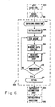
- Figure 6 is displayed a generalized flow chart of an example computer program which implements the basic centroid-accumulation technique of the present invention.
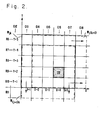
- Figure 1 is presented in simplified schematic form an example sensed image 100 such as may be obtained from a given field of view by means of conventional sensing and imaging devices.
- the large, intermediate, and small-sized objects respectively consisting of factory 110, house 120 and automobile 130.
- the basic purpose of the invention is to automatically determine whether small objects are present in the sensed scene and, if so, what their intra-scene locations are. With respect to the objects appearing in image 100, it is thus generally desired to ascertain the presence of, as well as the location of, automobile 130, while distinguishing the large-sized factory 110 and the intermediately-sized house 120.
- images such as scene 100 are typically composed of a plurality of picture elements called pixels, with the component pixels being arranged into a plurality of lines, and with each line being in turn composed of a plurality of pixels.
- these lines are labeled as rows Rl through R20, each of which has 20 pixels.
- pixels in the successive lines form columns Cl through C20.
- Any of the individual pixels in image 100 may then be conveniently identified by a unique row and column designation.
- automobile 130 may be seen to be located at the intersection pixel of row 9 and column 16. This pixel is given the symbolic designation of ⁇ R9, Cl6 ⁇ .
- window W x Shown superimposed on a portion of scene 100 is processing window W x .
- window W x is typically scanned over the entire image in a raster-like, step-wise combination of single-column and single-row increments.
- a determination is made as to which of the enclosed pixels coincides with the centroid of whatever objects (i.e., image data) or portions of objects are contained there within the window.
- window W x in its depicted position enclosing the 5-p.ixel-by-5-pixel array of pixels ⁇ R2, C10 ⁇ through ⁇ R2, C14 ⁇ to ⁇ R6, C10 ⁇ through ⁇ R6, C14 ⁇ , the factory-110 segment which occupies the column-10 pixels from R2 through R6 falls within the window. It may readily be demonstrated that the centroid of this window-enclosed object segment coincides with image pixel ⁇ R4, C10 ⁇ .
- centroid count for the ascertained pixel is incremented in an accumulating count-storage array whose purpose is to tabulate the number of times each pixel in the image has been determined to be a data centroid of the scanning window. Because a separate count must be kept for each of the pixels, the utilized tabulation array will generally have as many count-storage elements as there are pixels in the image being analyzed. Thus with respect to the factory-segment example begun above, the centroid processing at the W x window position as shown in Figure 1 would result in a centroid count increment for the storage element corresponding to pixel ⁇ R4, C10 ⁇ .
- the pixels corresponding to those count-array positions having high count- accumulations will be the intra-image locations of small-sized objects.
- the more-specific nature of the processing window may be better understood by examining the means conventionally utilized for assembling a composite scene such as image 100.
- the sensed scene- data of individual pixels is read into a storage array which has an individual and unique storage position for the data of each pixel in the image.
- a statement that the processing window has been placed at a given position in the image may be regarded as being in the nature of a term of art which refers to the more concrete operation of utilizing gating networks to read out of memory the ordered image data for each one of that set of pixels which is enclosed within the perimeter of the window as positioned. The ensuing processing is then performed on that data set as a unit.
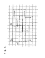
- FIG. 2 shows the processing window in the vicinity of the small automobile target 130 which appears in image 100 of Figure 1.
- Designated as “W jk " is the window located in position "jk,” where "j" is a generalized index related to the particular set of rows at which the window is positioned, while “k” is the analogous index with respect to the associated columns.
- W jk is the window located in position "jk,” where "j" is a generalized index related to the particular set of rows at which the window is positioned, while “k” is the analogous index with respect to the associated columns.
- the subject rows are seen to be R6 through R10, while the associated columns are C13 through C17.
- the windowing of this set of rows and columns means that there will be read out of the image-data memory the ordered contents of those storage positions which hold the image-data values of pixels ⁇ R6, C13 ⁇ through ⁇ R6, C171 to ⁇ R10, C13 ⁇ through ⁇ R10, C17).
- the centroiding operation which then follows is performed with respect to the data values of this windowed/memory-gated set of pixels.
- the window's width and height are respectively being M and N pixels in extent.
- the sizing dimensions M and N would be tailored according to several considerations.
- Intra-scene size is an important window-sizing consideration as an inherent consequence of the nature of the inventive-object-location technique. It will become apparent from example scene- analysis situations presented below that the subject technique may be regarded as being of enhanced effectiveness with respect to objects whose intra-scene size is smaller than about M/2 by N/2. Furthermore, it will likewise become apparent that in general the greater the differential between the (M/2)-by-(N/2) window area and the intra-scene area of a desired object, the more pronounced the small-size-location capability will become.
- intra-scene size will be a function not only of the desired object's absolute size but also of sensor-versus-scene geometry.
- the distance between the sensor and the sensed scene is a principal element of the sensor-versus-scene geometry and is hence a factor which has an important effect on a desired object's intra-scene size.
- the window dimensions would during the course of operation (although not during the processing of a given single scene) be adaptively adjusted to accommodate the consequentially-varying size of the type of object to be detected. It will be apparent that the window may also be dynamically altered where at different times it is desired to locate different types of objects having among themselves different relative sizes.
- the second of the considerations which can have an important influence on window dimensioning is the desired object's perceived shape. If a given object is likely to have a known, fixed orientation and will be perceived from the perspective of the sensor as being generally rectangular as opposed to either square or circular, a rectangular window may prove to be more appropriate to the achievement of the desired size discrimination than simply a square window of the type utilized for illustrative purposes throughout this specification.
- a square window of the type utilized for illustrative purposes throughout this specification.
- a first set of countervailing considerations may be given the generic designation of "clutter.”
- the general problem here is that the presence within the window of extraneous imagery will tend to adversely affect the ability of the required intra-window centroiding operation to focus on even a small object of interest.
- This type of clutter includes the situations where enclosed within the window at a given position are either more than one small target or portions of larger objects in addition to an object of interest.
- a second set of countervailing considerations is related to the processing capabilities of the hardware system which would typically be utilized to practice the inventive method in an actual operational environment.
- the desire to minimize execution times or computational storage requirements may provide another group of factors which limit window size as a consequence of a desire to limit the amount of pixel data which may advantageously be included in each of the required centroiding calculations.
- window dimensional optimization is simply a matter for empirical determination in light of not only the objects of interest and the nature of the scene to be viewed, but also of the equipment utilized for both image sensing and data analysis.
- the processing window be step-wise scanned over the entire sensed image.
- This general scanning requirement may be more specifically stated in terms of a collection of M-by-N windowed pixel sets upon which the likewise-required centroiding is performed.
- the more-specifically-stated requirement, as applied within each one of whatever image sectors are to be examined for the presence of small objects, is that each possible M-by-N grouping of the given sector's pixels must be subjected to the centroiding operation.
- the solid-perimetered window designated Wj k relates to the currently-processed 5-by-5 pixel set of the pixels from rows R6 through R10 and columns C13 through C17, with the indices "j" and "k” respectively designating in a general way the particular set of rows and columns of that window.
- the window is right-shifted by one column, with the R6 through R10 pixels of column 17 being utilized in the new centroiding computation in place of the R6 through R10 pixels of column 13.
- the single-column right-shift continues until the right edge of the scene is reached, at which point the processing is then carried on with a single-row down-shifted sequence of windows referenced with respect to the R7-through-Rll row set.
- W(j+ 1 ) k shows the row- incremented window as it once again moves into the vicinity of the small target 130.
- the shift sequence typically begins at the first available M-by-N cluster of pixels in the upper left corner of the image where the single-column right-shifting is performed across the entire scene with respect to the first available set of N rows.
- the processing then continues through the successive row-increment - plus- column-shift sequences until all of the M-by-N pixel clusters of all of the scene portions of interest have been centroided.
- the window is not allowed to overlap the edges of the scene. Near scene boundaries, therefore, the centroiding is thus typically performed only with respect to window positions in which a full complement of M-by-N pixels is available.
- centroiding becomes a determination of that point within each window position which may be regarded as being in the nature of an effective center of the image intensities enclosed by the given window.
- this effective center is not only very useful in terms of the net results achieved by the invention itself, but is also especially expedient in facilitating the achievement of these results.
- the centroid's usefulness is apparent in those operational environments where a principal processing objective is the ascertainment, for each small object in the sensed scene, of a single pixel which may be taken as being representative of the intra-image location of that object.
- the centroid's expediency follows from a consequential property which contributes significantly to the conceptual basis of the inventive method.
- This property is the tendency of the centroid of those objects which are significantly smaller-than the window size, as distinguished from those whose size is of the same order as or larger than the window, to remain stationary while the window is being moved through a sequential plurality of step-wise-incremented positions. It is this stationarity property, further clarified in examples to be presented below, which is a major factor in bringing about the accumulation effect used as the final indicator of the possible presence and resulting location of any small point object in the scene.
- centroid calculation requires as inputs two quantities for each pixel:
- the frame of reference used for centroiding-related displacement measurements is arbitrary as long as there is reference- frame consistency from one centroid computation to the next and hence from one window position to the next.
- Simply employing a Cartesian coordinate system in which the row and column designators become the respective (x,y) units of displacement measurement is both sufficient and straightforward.
- Window Wj k of Figure 2 may thus be seen to contain a coordinate system of this nature.
- the lower left-hand corner is designated the origin.
- the ordinal designators of the 1st through Mth columns and 1st through Nth rows become respectively the x and y units which are to be used in the associated centroid calculation.
- centroid calculations in a specialized class of operating environments also typically employ image-intensities which are adjusted so as to cause the computational results to become more-meaningful representations of the associated windows' intensity centers.
- image-intensities which are adjusted so as to cause the computational results to become more-meaningful representations of the associated windows' intensity centers.
- the need for the intensity adjustments is a consequence of an operationally-adverse interaction between, on one hand, the nature of the centroid calculations themselves and, on the other, the nature of the image data presented for inventive processing in these specialized operational situations.
- a particular problem situation often presented is that in which a desired small object, by itself yielding a sensed image intensity of a given level, is observed while effectively superimposed on a field-of-view background having its own, nonzero image-intensity level.
- the background is said to form a "pedestal" upon which the object rests.
- the process of pedestal removal by reducing background intensity to zero is typically achieved in a relatively simple manner by determining an average intensity value within a given area and then reducing all "raw" intensity values within that area by this determined average amount.
- windowing typically performed in the practice of this invention, where the centroiding is carried out only with respect to a localized group of pixels, it becomes apparent, once the need for pedestal-removal is recognized, that the removal must be done on a basis which is localized to the particular cluster of pixels which are being analyzed for the presence of small objects and hence which are included in a given centroiding computation.
- the averaging by which background reduction is typically achieved should, for the purposes of optimizing inventive performance, be performed on the basis of only those intensity values which are sensed in the immediate vicinity of a given subject pixel.
- the pedestal removal and hence average-level determination is performed on a windowed set of pixels.
- the centroid-by- centroid process of the first pedestal-removal technique involves the following: Each time the basic processing window is incremented to a new position and thus encloses a new set of pixels, the actual centroid calculation itself is not performed until a determination has been made of what is the average intensity level of all of the applied "raw" levels of each of the pixels in that given set. In a centroid-calculation memory, the "raw" intensity value of each pixel is reduced by the determined average.
- centroid calculation for that one window then proceeds on the basis of the reduced intensity values. Once that window's centroiding is completed, the window is shifted to enclose a new set of pixels where the centroiding operation is again preceded by an associated average-level determination performed with respect to applied intensity values only.
- the averaging window was and may be utilized as follows with respect to an actual image:
- the window is step-wise scanned over the entire image of interest in a manner similar to that in which the basic centroiding window is scanned over the scene.
- acceptable intensity- reduction performance is achieved by moving the window in increments of two columns and then two rows at a time, instead of the single-unit increments utilized for centroiding.
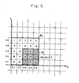
- the average level of all the applied intensity data values for the thirty-two pixels enclosed by outer window 350a is determined.
- the intensity values which result from the process of subtracting this determined average from the "raw" intensity values of each of the four pixels enclosed by the inner window 350b are then stored in a working array having storage positions equal in number to, and uniquely corresponding to, those of the image array.
- the presented image values of the pixels enclosed by the inner window are themselves left unaltered for the sake of the averaging calculations which are then subsequently performed when the averaging window shifts to its next succeeding position.
- the rationale for the double-column and double-row steps of the outer window is apparent from the four-pixel nature of the inner window.
- the local centroid designation ⁇ X l , Y l ⁇ may then through well-known coordinate-transformation techniques be readily converted into a global row and column designation for that one, overall-scene pixel which has been determined in this fashion to be the centroid of the data currently contained within the window.
- the I r quantity may be more precisely defined in terms of the two pedestal-removal techniques as follows:
- I r is simply the reduced intensity value obtained from the appropriate position of the working storage array. It may be noted that in the performance of this reduction, a zero- thresholding "maximum-of" function, described above and also incorporated in the example subroutine HIGHPASS presented below, would typically be employed.
- the net outcome of each of the centroiding calculations is an incrementing of a centroid count for that intra-scene pixel determined to coincide with the current intra-window centroid.
- the conventional accumulation array utilized for holding the resulting pixel-by-pixel centroid counts as finally incremented may be interrogated by means of various memory-inventory techniques. Because smaller objects will tend to have given rise to the larger of such centroid counts, the pixels corresponding to those accumulation-array storage positions found during the course of the interrogation to have high counts will in accordance with the invention be deemed to be the intra-scene locations of small point targets.
- Accumulation-array interrogation is the process of examining the array's tabulated contents for those high centroid counts which indicate the presence of a small object at the associated pixel.
- peak-count detection and count thresholding are what will be designated as peak-count detection and count thresholding.
- the accumulation array is simply checked to see which of its tabulated centroid counts is the highest.
- the associated pixel is then designated as being the intra-scene location of a small target.
- the peak detection may be performed iteratively by first, reducing to zero the count of the array position having the first-detected peak; second, re-examining the array contents for a second peak; third, location- designating the second-detected peak; and then repeating the peak-nullification, contents-re-examination and location-designation sequence.
- count-thresholding is the related interrogation procedure in which the accumulation array is checked not for that one count which is higher than the rest but for those counts which are higher than some threshold. This procedure follows from the observation that, in many operational situations of interest, desired small targets will tend to give rise to centroid counts of at least a certain level. In such situations it may then be possible to establish a centroid-count threshold and to declare that whenever in the course of an accumulation-array interrogation a count is found to exceed this threshold, the count will be taken as an indication of the presence of a small target. It will at times also be possible to analogously ascertain an intermediate range of centroid counts which may be used as indicators of objects of intermediate size.
- Such thresholds will typically tend to be quantities which can be determined on an empirical basis only and will be dependent upon the unique characteristics of the given processing situation at hand. Relevant considerations to be evaluated in setting the thresholds will include the size of the centroiding window, the expected size of the objects of interest, the expected concentration of objects, and the extent to which extraneous "clutter" may be expected to be enclosed along with an object of interest by the centroiding window in any one of its positions.
- a count threshold of 20 may be sufficient for small-object-location purposes.
- the double centroid count for the identified second pixel was obtained in part through the use of a processing convention in which that pixel to the right of and, if necessary, one row up from an ambiguous centroid location is deemed to be the centroid location in those situations where the strict results obtained by the centroiding calculations will place the centroid on a junction between adjacent pixels.
- Alternative but analogous ambiguity-resolution conventions are readily apparent. For example, in one actual realization the ambiguities took the form of fractional remainders following the divisions by ⁇ I r . The preferred manner of dealing with such remainders was to simply truncate them.
- the resolution- by-truncation caused that pixel which was to the left of and, if necessary, above the true centroid position to be deemed the centroid location.
- Figure 5 presents this situation in expanded form. Identifying the enclosed pixels from left to right beginning at the upper left corner, and letting all image-intensity values be unity, yields the following relations:
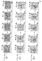
- CENPROCESS is a FORTRAN-language realization of the essential steps of the invention.
- FORTRAN subroutines PEAKDETECT and HIGHPASS are a realization of the centroid-count interrogation process, while HIGHPASS performs pedestal removal in accordance with the second of the removal techniques described previously.
- the REFPOINTS output of the PEAKDETECT subroutine will be the determined locations of small targets. In an actual operational situation, these location designations would then be made available for further track processing.
- routines as set forth are merely exemplary.
Landscapes
- Engineering & Computer Science (AREA)
- Physics & Mathematics (AREA)
- General Physics & Mathematics (AREA)
- Theoretical Computer Science (AREA)
- Multimedia (AREA)
- Computer Vision & Pattern Recognition (AREA)
- Nonlinear Science (AREA)
- Image Analysis (AREA)
- Control Of Position Or Direction (AREA)
- Testing Of Balance (AREA)
Applications Claiming Priority (2)
| Application Number | Priority Date | Filing Date | Title |
|---|---|---|---|
| US06/363,318 US4499597A (en) | 1982-03-29 | 1982-03-29 | Small-object location utilizing centroid accumulation |
| US363318 | 1982-03-29 |
Publications (3)
| Publication Number | Publication Date |
|---|---|
| EP0090159A2 true EP0090159A2 (de) | 1983-10-05 |
| EP0090159A3 EP0090159A3 (en) | 1984-11-14 |
| EP0090159B1 EP0090159B1 (de) | 1987-12-02 |
Family
ID=23429731
Family Applications (1)
| Application Number | Title | Priority Date | Filing Date |
|---|---|---|---|
| EP83101380A Expired EP0090159B1 (de) | 1982-03-29 | 1983-02-14 | Positionsbestimmung von Kleinobjekten mittels der Aufspeicherung von Zentroiden |
Country Status (5)
| Country | Link |
|---|---|
| US (1) | US4499597A (de) |
| EP (1) | EP0090159B1 (de) |
| JP (1) | JPS5916023A (de) |
| DE (2) | DE3374818D1 (de) |
| IL (1) | IL67821A (de) |
Families Citing this family (30)
| Publication number | Priority date | Publication date | Assignee | Title |
|---|---|---|---|---|
| US4783829A (en) * | 1983-02-23 | 1988-11-08 | Hitachi, Ltd. | Pattern recognition apparatus |
| US4550432A (en) * | 1983-04-13 | 1985-10-29 | At&T Bell Laboratories | Image processor using a moment generator |
| US4637052A (en) * | 1983-10-24 | 1987-01-13 | The United States Of America As Represented By The Department Of Energy | Method and apparatus for enhancing microchannel plate data |
| US4571635A (en) * | 1984-02-17 | 1986-02-18 | Minnesota Mining And Manufacturing Company | Method of image enhancement by raster scanning |
| US4628534A (en) * | 1984-07-06 | 1986-12-09 | Honeywell Information Systems Inc. | Method for changing the resolution of compressed image data |
| JPH0778823B2 (ja) * | 1985-12-09 | 1995-08-23 | 株式会社応用計測研究所 | 画像処理方法 |
| US4760247A (en) * | 1986-04-04 | 1988-07-26 | Bally Manufacturing Company | Optical card reader utilizing area image processing |
| JPS62267610A (ja) * | 1986-05-16 | 1987-11-20 | Fuji Electric Co Ltd | 対象パタ−ンの回転角検出方式 |
| JPH0810132B2 (ja) * | 1986-06-04 | 1996-01-31 | 富士電機株式会社 | 対象パタ−ンの回転角検出方式 |
| US4907152A (en) * | 1986-09-25 | 1990-03-06 | The Boeing Company | Method of improving CT resolution |
| US4955062A (en) * | 1986-12-10 | 1990-09-04 | Canon Kabushiki Kaisha | Pattern detecting method and apparatus |
| US4821336A (en) * | 1987-02-19 | 1989-04-11 | Gtx Corporation | Method and apparatus for simplifying runlength data from scanning of images |
| US4797806A (en) * | 1987-02-19 | 1989-01-10 | Gtx Corporation | High speed serial pixel neighborhood processor and method |
| DE3708795C2 (de) * | 1987-03-18 | 1995-08-03 | Gsf Forschungszentrum Umwelt | Verfahren zur Größenselektion in Videoechtzeit |
| US4939672A (en) * | 1987-11-09 | 1990-07-03 | Tektronix, Inc. | Method and apparatus for classifying graphics segments to facilitate pick and display operation |
| FR2625396B1 (fr) * | 1987-12-23 | 1990-06-01 | Europ Agence Spatiale | Procede et dispositif pour determiner la position du centre d'un signal lumineux recu dans un detecteur a mosaique a couplage de charges |
| US4969200A (en) * | 1988-03-25 | 1990-11-06 | Texas Instruments Incorporated | Target autoalignment for pattern inspector or writer |
| US4991092A (en) * | 1988-08-12 | 1991-02-05 | The Regents Of The University Of California | Image processor for enhancing contrast between subregions of a region of interest |
| US5187777A (en) * | 1989-09-21 | 1993-02-16 | Loral Aerospace Corp. | Multi-function pre-processor for target tracking |
| US5164994A (en) * | 1989-12-21 | 1992-11-17 | Hughes Aircraft Company | Solder joint locator |
| GB9102713D0 (en) * | 1991-02-08 | 1991-03-27 | Univ London | Centroiding method for photon counting detectors |
| US5731539A (en) * | 1992-10-02 | 1998-03-24 | Motorola, Inc. | Target detection method |
| US5455899A (en) * | 1992-12-31 | 1995-10-03 | International Business Machines Corporation | High speed image data processing circuit |
| US5479526A (en) * | 1993-03-23 | 1995-12-26 | Martin Marietta | Pixel designator for small objects |
| JP3433983B2 (ja) * | 1993-09-20 | 2003-08-04 | 株式会社日立製作所 | 画像縮小装置および画像縮小方法 |
| JPH0841778A (ja) * | 1994-08-01 | 1996-02-13 | Kanebo Ltd | 布帛の起毛装置 |
| IT1274405B (it) * | 1995-04-28 | 1997-07-17 | San Raffaele Centro Fond | Dispositivo di posizionamento e centramento automatico di testa ottica di microscopio |
| DE19528465C2 (de) * | 1995-08-03 | 2000-07-06 | Leica Geosystems Ag | Verfahren und Vorrichtung zur schnellen Erfassung der Lage einer Zielmarke |
| US9129185B1 (en) * | 2012-05-21 | 2015-09-08 | The Boeing Company | System and method for reducing image clutter |
| CN115205369B (zh) * | 2022-08-03 | 2024-04-02 | 江苏科技大学 | 一种抗大气湍流的灯靶图像位移提取算法 |
Family Cites Families (5)
| Publication number | Priority date | Publication date | Assignee | Title |
|---|---|---|---|---|
| US3292148A (en) * | 1961-05-08 | 1966-12-13 | Little Inc A | Character recognition apparatus using two-dimensional density functions |
| US3274549A (en) * | 1962-05-04 | 1966-09-20 | Kollsman Instr Corp | Automatic pattern recognition system |
| US3829614A (en) * | 1970-02-11 | 1974-08-13 | Saab Scania Ab | Automatic video contrast tracker |
| US4298858A (en) * | 1980-03-27 | 1981-11-03 | The United States Of America As Represented By The Secretary Of The Air Force | Method and apparatus for augmenting binary patterns |
| US4398256A (en) * | 1981-03-16 | 1983-08-09 | Hughes Aircraft Company | Image processing architecture |
-
1982
- 1982-03-29 US US06/363,318 patent/US4499597A/en not_active Expired - Lifetime
-
1983
- 1983-02-01 IL IL67821A patent/IL67821A/xx not_active IP Right Cessation
- 1983-02-14 DE DE8383101380T patent/DE3374818D1/de not_active Expired
- 1983-02-14 DE DE198383101380T patent/DE90159T1/de active Pending
- 1983-02-14 EP EP83101380A patent/EP0090159B1/de not_active Expired
- 1983-03-29 JP JP58051731A patent/JPS5916023A/ja active Granted
Also Published As
| Publication number | Publication date |
|---|---|
| IL67821A (en) | 1986-11-30 |
| JPS5916023A (ja) | 1984-01-27 |
| DE90159T1 (de) | 1984-04-12 |
| JPH05749B2 (de) | 1993-01-06 |
| US4499597A (en) | 1985-02-12 |
| DE3374818D1 (en) | 1988-01-14 |
| EP0090159A3 (en) | 1984-11-14 |
| EP0090159B1 (de) | 1987-12-02 |
Similar Documents
| Publication | Publication Date | Title |
|---|---|---|
| EP0090159B1 (de) | Positionsbestimmung von Kleinobjekten mittels der Aufspeicherung von Zentroiden | |
| US5870494A (en) | Method for determining orientation of contour line segment in local area and for determining straight line and corner | |
| US5073958A (en) | Method of detecting edges in images | |
| US5072384A (en) | Method and system for automated computerized analysis of sizes of hearts and lungs in digital chest radiographs | |
| DE60130598T2 (de) | Verfahren and Vorrichtung zum automatischen Einstellen eines Abtasttores in Puls-Dopplerultraschallbildgebung | |
| US4736439A (en) | Image preprocessing by modified median filter | |
| US5034969A (en) | Tomographic image diagnostic method and apparatus including automatic ROI setting means | |
| JP7016549B2 (ja) | 肝臓境界の識別方法及びシステム | |
| EP1498847A2 (de) | Verfahren zur Ermittlung einer Tiefenkarte aus einem digitalen Bild | |
| US5321764A (en) | Identification of wheat cultivars by visual imaging | |
| JPWO1993007580A1 (ja) | 輪郭線分の局所領域における方位決定方法および線分と角の決定方法 | |
| JPH06237925A (ja) | ディジタル胸部レントゲン写真において関心領域の選択と中隔線の検出を行なう自動化方法およびそのシステム | |
| US20020061126A1 (en) | Method and system for extracting spine frontal geometrical data including vertebra pedicle locations | |
| JPH01166267A (ja) | 画像化方法および装置 | |
| JPH077444B2 (ja) | 三次元画像の連結成分抽出装置 | |
| EP0504633A2 (de) | Filterprozessor zur Störechounterdrückung | |
| JPH06290276A (ja) | 3次元場面の映像化用配置及び方法 | |
| US5034988A (en) | Method and system for fitting image positions | |
| JP2791303B2 (ja) | 1つの連結領域が示すコロニーの個数を識別する識別方法及びこれを用いたコロニー計数装置 | |
| CN110084818B (zh) | 动态下采样图像分割方法 | |
| CN113554688A (zh) | 一种基于单目视觉的o型密封圈尺寸测量方法 | |
| US4598419A (en) | Automatic device for the statistical analysis of an object | |
| KR100461264B1 (ko) | 명암도와 밝기의 변화에 독립적인 초음파 종괴영상을 검색하는 방법 | |
| Fernandes et al. | Detection and quantification of microorganisms in a heterogeneous foodstuff by image analysis | |
| JPS63221488A (ja) | 画像内濃淡領域検出装置 |
Legal Events
| Date | Code | Title | Description |
|---|---|---|---|
| PUAI | Public reference made under article 153(3) epc to a published international application that has entered the european phase |
Free format text: ORIGINAL CODE: 0009012 |
|
| AK | Designated contracting states |
Designated state(s): DE FR GB |
|
| DET | De: translation of patent claims | ||
| PUAL | Search report despatched |
Free format text: ORIGINAL CODE: 0009013 |
|
| AK | Designated contracting states |
Designated state(s): DE FR GB |
|
| 17P | Request for examination filed |
Effective date: 19850425 |
|
| RAP1 | Party data changed (applicant data changed or rights of an application transferred) |
Owner name: HUGHES AIRCRAFT COMPANY |
|
| 17Q | First examination report despatched |
Effective date: 19870218 |
|
| GRAA | (expected) grant |
Free format text: ORIGINAL CODE: 0009210 |
|
| AK | Designated contracting states |
Kind code of ref document: B1 Designated state(s): DE FR GB |
|
| REF | Corresponds to: |
Ref document number: 3374818 Country of ref document: DE Date of ref document: 19880114 |
|
| ET | Fr: translation filed | ||
| PLBE | No opposition filed within time limit |
Free format text: ORIGINAL CODE: 0009261 |
|
| STAA | Information on the status of an ep patent application or granted ep patent |
Free format text: STATUS: NO OPPOSITION FILED WITHIN TIME LIMIT |
|
| 26N | No opposition filed | ||
| REG | Reference to a national code |
Ref country code: GB Ref legal event code: 732E |
|
| REG | Reference to a national code |
Ref country code: GB Ref legal event code: IF02 |
|
| PGFP | Annual fee paid to national office [announced via postgrant information from national office to epo] |
Ref country code: FR Payment date: 20020114 Year of fee payment: 20 |
|
| PGFP | Annual fee paid to national office [announced via postgrant information from national office to epo] |
Ref country code: GB Payment date: 20020117 Year of fee payment: 20 |
|
| PGFP | Annual fee paid to national office [announced via postgrant information from national office to epo] |
Ref country code: DE Payment date: 20020121 Year of fee payment: 20 |
|
| PG25 | Lapsed in a contracting state [announced via postgrant information from national office to epo] |
Ref country code: GB Free format text: LAPSE BECAUSE OF EXPIRATION OF PROTECTION Effective date: 20030213 |
|
| REG | Reference to a national code |
Ref country code: GB Ref legal event code: PE20 Effective date: 20030213 |