EP0090159A2 - Small-object location utilizing centroid accumulation - Google Patents
Small-object location utilizing centroid accumulation Download PDFInfo
- Publication number
- EP0090159A2 EP0090159A2 EP83101380A EP83101380A EP0090159A2 EP 0090159 A2 EP0090159 A2 EP 0090159A2 EP 83101380 A EP83101380 A EP 83101380A EP 83101380 A EP83101380 A EP 83101380A EP 0090159 A2 EP0090159 A2 EP 0090159A2
- Authority
- EP
- European Patent Office
- Prior art keywords
- window
- centroid
- image
- pixel
- pixels
- Prior art date
- Legal status (The legal status is an assumption and is not a legal conclusion. Google has not performed a legal analysis and makes no representation as to the accuracy of the status listed.)
- Granted
Links
Images

Classifications
-
- G—PHYSICS
- G06—COMPUTING; CALCULATING OR COUNTING
- G06T—IMAGE DATA PROCESSING OR GENERATION, IN GENERAL
- G06T7/00—Image analysis
-
- G—PHYSICS
- G06—COMPUTING; CALCULATING OR COUNTING
- G06V—IMAGE OR VIDEO RECOGNITION OR UNDERSTANDING
- G06V10/00—Arrangements for image or video recognition or understanding
- G06V10/20—Image preprocessing
-
- G—PHYSICS
- G06—COMPUTING; CALCULATING OR COUNTING
- G06V—IMAGE OR VIDEO RECOGNITION OR UNDERSTANDING
- G06V10/00—Arrangements for image or video recognition or understanding
- G06V10/20—Image preprocessing
- G06V10/24—Aligning, centring, orientation detection or correction of the image
-
- G—PHYSICS
- G06—COMPUTING; CALCULATING OR COUNTING
- G06V—IMAGE OR VIDEO RECOGNITION OR UNDERSTANDING
- G06V10/00—Arrangements for image or video recognition or understanding
- G06V10/20—Image preprocessing
- G06V10/36—Applying a local operator, i.e. means to operate on image points situated in the vicinity of a given point; Non-linear local filtering operations, e.g. median filtering
-
- G—PHYSICS
- G06—COMPUTING; CALCULATING OR COUNTING
- G06V—IMAGE OR VIDEO RECOGNITION OR UNDERSTANDING
- G06V10/00—Arrangements for image or video recognition or understanding
- G06V10/40—Extraction of image or video features
- G06V10/42—Global feature extraction by analysis of the whole pattern, e.g. using frequency domain transformations or autocorrelation
Definitions
- the invention relates in general to image processing and in particular to a technique for locating small objects in a given field of view.
- the disclosed invention which in one of its aspects causes a processing window to be step-wise scanned over a sensed, pixel-based image, with the centroid pixel of each set of image data successively contained within the scanning window being determined, and with a tabulation being made of the number of times each image pixel is thusly determined to be the windowed-data centroid.
- a processing window to be step-wise scanned over a sensed, pixel-based image, with the centroid pixel of each set of image data successively contained within the scanning window being determined, and with a tabulation being made of the number of times each image pixel is thusly determined to be the windowed-data centroid.
- Figure 5 illustrates various aspects of a windowed-data centroiding calculation
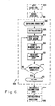
- Figure 6 is displayed a generalized flow chart of an example computer program which implements the basic centroid-accumulation technique of the present invention.
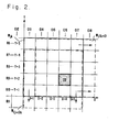
- Figure 1 is presented in simplified schematic form an example sensed image 100 such as may be obtained from a given field of view by means of conventional sensing and imaging devices.
- the large, intermediate, and small-sized objects respectively consisting of factory 110, house 120 and automobile 130.
- the basic purpose of the invention is to automatically determine whether small objects are present in the sensed scene and, if so, what their intra-scene locations are. With respect to the objects appearing in image 100, it is thus generally desired to ascertain the presence of, as well as the location of, automobile 130, while distinguishing the large-sized factory 110 and the intermediately-sized house 120.
- images such as scene 100 are typically composed of a plurality of picture elements called pixels, with the component pixels being arranged into a plurality of lines, and with each line being in turn composed of a plurality of pixels.
- these lines are labeled as rows Rl through R20, each of which has 20 pixels.
- pixels in the successive lines form columns Cl through C20.
- Any of the individual pixels in image 100 may then be conveniently identified by a unique row and column designation.
- automobile 130 may be seen to be located at the intersection pixel of row 9 and column 16. This pixel is given the symbolic designation of ⁇ R9, Cl6 ⁇ .
- window W x Shown superimposed on a portion of scene 100 is processing window W x .
- window W x is typically scanned over the entire image in a raster-like, step-wise combination of single-column and single-row increments.
- a determination is made as to which of the enclosed pixels coincides with the centroid of whatever objects (i.e., image data) or portions of objects are contained there within the window.
- window W x in its depicted position enclosing the 5-p.ixel-by-5-pixel array of pixels ⁇ R2, C10 ⁇ through ⁇ R2, C14 ⁇ to ⁇ R6, C10 ⁇ through ⁇ R6, C14 ⁇ , the factory-110 segment which occupies the column-10 pixels from R2 through R6 falls within the window. It may readily be demonstrated that the centroid of this window-enclosed object segment coincides with image pixel ⁇ R4, C10 ⁇ .
- centroid count for the ascertained pixel is incremented in an accumulating count-storage array whose purpose is to tabulate the number of times each pixel in the image has been determined to be a data centroid of the scanning window. Because a separate count must be kept for each of the pixels, the utilized tabulation array will generally have as many count-storage elements as there are pixels in the image being analyzed. Thus with respect to the factory-segment example begun above, the centroid processing at the W x window position as shown in Figure 1 would result in a centroid count increment for the storage element corresponding to pixel ⁇ R4, C10 ⁇ .
- the pixels corresponding to those count-array positions having high count- accumulations will be the intra-image locations of small-sized objects.
- the more-specific nature of the processing window may be better understood by examining the means conventionally utilized for assembling a composite scene such as image 100.
- the sensed scene- data of individual pixels is read into a storage array which has an individual and unique storage position for the data of each pixel in the image.
- a statement that the processing window has been placed at a given position in the image may be regarded as being in the nature of a term of art which refers to the more concrete operation of utilizing gating networks to read out of memory the ordered image data for each one of that set of pixels which is enclosed within the perimeter of the window as positioned. The ensuing processing is then performed on that data set as a unit.
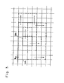
- FIG. 2 shows the processing window in the vicinity of the small automobile target 130 which appears in image 100 of Figure 1.
- Designated as “W jk " is the window located in position "jk,” where "j" is a generalized index related to the particular set of rows at which the window is positioned, while “k” is the analogous index with respect to the associated columns.
- W jk is the window located in position "jk,” where "j" is a generalized index related to the particular set of rows at which the window is positioned, while “k” is the analogous index with respect to the associated columns.
- the subject rows are seen to be R6 through R10, while the associated columns are C13 through C17.
- the windowing of this set of rows and columns means that there will be read out of the image-data memory the ordered contents of those storage positions which hold the image-data values of pixels ⁇ R6, C13 ⁇ through ⁇ R6, C171 to ⁇ R10, C13 ⁇ through ⁇ R10, C17).
- the centroiding operation which then follows is performed with respect to the data values of this windowed/memory-gated set of pixels.
- the window's width and height are respectively being M and N pixels in extent.
- the sizing dimensions M and N would be tailored according to several considerations.
- Intra-scene size is an important window-sizing consideration as an inherent consequence of the nature of the inventive-object-location technique. It will become apparent from example scene- analysis situations presented below that the subject technique may be regarded as being of enhanced effectiveness with respect to objects whose intra-scene size is smaller than about M/2 by N/2. Furthermore, it will likewise become apparent that in general the greater the differential between the (M/2)-by-(N/2) window area and the intra-scene area of a desired object, the more pronounced the small-size-location capability will become.
- intra-scene size will be a function not only of the desired object's absolute size but also of sensor-versus-scene geometry.
- the distance between the sensor and the sensed scene is a principal element of the sensor-versus-scene geometry and is hence a factor which has an important effect on a desired object's intra-scene size.
- the window dimensions would during the course of operation (although not during the processing of a given single scene) be adaptively adjusted to accommodate the consequentially-varying size of the type of object to be detected. It will be apparent that the window may also be dynamically altered where at different times it is desired to locate different types of objects having among themselves different relative sizes.
- the second of the considerations which can have an important influence on window dimensioning is the desired object's perceived shape. If a given object is likely to have a known, fixed orientation and will be perceived from the perspective of the sensor as being generally rectangular as opposed to either square or circular, a rectangular window may prove to be more appropriate to the achievement of the desired size discrimination than simply a square window of the type utilized for illustrative purposes throughout this specification.
- a square window of the type utilized for illustrative purposes throughout this specification.
- a first set of countervailing considerations may be given the generic designation of "clutter.”
- the general problem here is that the presence within the window of extraneous imagery will tend to adversely affect the ability of the required intra-window centroiding operation to focus on even a small object of interest.
- This type of clutter includes the situations where enclosed within the window at a given position are either more than one small target or portions of larger objects in addition to an object of interest.
- a second set of countervailing considerations is related to the processing capabilities of the hardware system which would typically be utilized to practice the inventive method in an actual operational environment.
- the desire to minimize execution times or computational storage requirements may provide another group of factors which limit window size as a consequence of a desire to limit the amount of pixel data which may advantageously be included in each of the required centroiding calculations.
- window dimensional optimization is simply a matter for empirical determination in light of not only the objects of interest and the nature of the scene to be viewed, but also of the equipment utilized for both image sensing and data analysis.
- the processing window be step-wise scanned over the entire sensed image.
- This general scanning requirement may be more specifically stated in terms of a collection of M-by-N windowed pixel sets upon which the likewise-required centroiding is performed.
- the more-specifically-stated requirement, as applied within each one of whatever image sectors are to be examined for the presence of small objects, is that each possible M-by-N grouping of the given sector's pixels must be subjected to the centroiding operation.
- the solid-perimetered window designated Wj k relates to the currently-processed 5-by-5 pixel set of the pixels from rows R6 through R10 and columns C13 through C17, with the indices "j" and "k” respectively designating in a general way the particular set of rows and columns of that window.
- the window is right-shifted by one column, with the R6 through R10 pixels of column 17 being utilized in the new centroiding computation in place of the R6 through R10 pixels of column 13.
- the single-column right-shift continues until the right edge of the scene is reached, at which point the processing is then carried on with a single-row down-shifted sequence of windows referenced with respect to the R7-through-Rll row set.
- W(j+ 1 ) k shows the row- incremented window as it once again moves into the vicinity of the small target 130.
- the shift sequence typically begins at the first available M-by-N cluster of pixels in the upper left corner of the image where the single-column right-shifting is performed across the entire scene with respect to the first available set of N rows.
- the processing then continues through the successive row-increment - plus- column-shift sequences until all of the M-by-N pixel clusters of all of the scene portions of interest have been centroided.
- the window is not allowed to overlap the edges of the scene. Near scene boundaries, therefore, the centroiding is thus typically performed only with respect to window positions in which a full complement of M-by-N pixels is available.
- centroiding becomes a determination of that point within each window position which may be regarded as being in the nature of an effective center of the image intensities enclosed by the given window.
- this effective center is not only very useful in terms of the net results achieved by the invention itself, but is also especially expedient in facilitating the achievement of these results.
- the centroid's usefulness is apparent in those operational environments where a principal processing objective is the ascertainment, for each small object in the sensed scene, of a single pixel which may be taken as being representative of the intra-image location of that object.
- the centroid's expediency follows from a consequential property which contributes significantly to the conceptual basis of the inventive method.
- This property is the tendency of the centroid of those objects which are significantly smaller-than the window size, as distinguished from those whose size is of the same order as or larger than the window, to remain stationary while the window is being moved through a sequential plurality of step-wise-incremented positions. It is this stationarity property, further clarified in examples to be presented below, which is a major factor in bringing about the accumulation effect used as the final indicator of the possible presence and resulting location of any small point object in the scene.
- centroid calculation requires as inputs two quantities for each pixel:
- the frame of reference used for centroiding-related displacement measurements is arbitrary as long as there is reference- frame consistency from one centroid computation to the next and hence from one window position to the next.
- Simply employing a Cartesian coordinate system in which the row and column designators become the respective (x,y) units of displacement measurement is both sufficient and straightforward.
- Window Wj k of Figure 2 may thus be seen to contain a coordinate system of this nature.
- the lower left-hand corner is designated the origin.
- the ordinal designators of the 1st through Mth columns and 1st through Nth rows become respectively the x and y units which are to be used in the associated centroid calculation.
- centroid calculations in a specialized class of operating environments also typically employ image-intensities which are adjusted so as to cause the computational results to become more-meaningful representations of the associated windows' intensity centers.
- image-intensities which are adjusted so as to cause the computational results to become more-meaningful representations of the associated windows' intensity centers.
- the need for the intensity adjustments is a consequence of an operationally-adverse interaction between, on one hand, the nature of the centroid calculations themselves and, on the other, the nature of the image data presented for inventive processing in these specialized operational situations.
- a particular problem situation often presented is that in which a desired small object, by itself yielding a sensed image intensity of a given level, is observed while effectively superimposed on a field-of-view background having its own, nonzero image-intensity level.
- the background is said to form a "pedestal" upon which the object rests.
- the process of pedestal removal by reducing background intensity to zero is typically achieved in a relatively simple manner by determining an average intensity value within a given area and then reducing all "raw" intensity values within that area by this determined average amount.
- windowing typically performed in the practice of this invention, where the centroiding is carried out only with respect to a localized group of pixels, it becomes apparent, once the need for pedestal-removal is recognized, that the removal must be done on a basis which is localized to the particular cluster of pixels which are being analyzed for the presence of small objects and hence which are included in a given centroiding computation.
- the averaging by which background reduction is typically achieved should, for the purposes of optimizing inventive performance, be performed on the basis of only those intensity values which are sensed in the immediate vicinity of a given subject pixel.
- the pedestal removal and hence average-level determination is performed on a windowed set of pixels.
- the centroid-by- centroid process of the first pedestal-removal technique involves the following: Each time the basic processing window is incremented to a new position and thus encloses a new set of pixels, the actual centroid calculation itself is not performed until a determination has been made of what is the average intensity level of all of the applied "raw" levels of each of the pixels in that given set. In a centroid-calculation memory, the "raw" intensity value of each pixel is reduced by the determined average.
- centroid calculation for that one window then proceeds on the basis of the reduced intensity values. Once that window's centroiding is completed, the window is shifted to enclose a new set of pixels where the centroiding operation is again preceded by an associated average-level determination performed with respect to applied intensity values only.
- the averaging window was and may be utilized as follows with respect to an actual image:
- the window is step-wise scanned over the entire image of interest in a manner similar to that in which the basic centroiding window is scanned over the scene.
- acceptable intensity- reduction performance is achieved by moving the window in increments of two columns and then two rows at a time, instead of the single-unit increments utilized for centroiding.
- the average level of all the applied intensity data values for the thirty-two pixels enclosed by outer window 350a is determined.
- the intensity values which result from the process of subtracting this determined average from the "raw" intensity values of each of the four pixels enclosed by the inner window 350b are then stored in a working array having storage positions equal in number to, and uniquely corresponding to, those of the image array.
- the presented image values of the pixels enclosed by the inner window are themselves left unaltered for the sake of the averaging calculations which are then subsequently performed when the averaging window shifts to its next succeeding position.
- the rationale for the double-column and double-row steps of the outer window is apparent from the four-pixel nature of the inner window.
- the local centroid designation ⁇ X l , Y l ⁇ may then through well-known coordinate-transformation techniques be readily converted into a global row and column designation for that one, overall-scene pixel which has been determined in this fashion to be the centroid of the data currently contained within the window.
- the I r quantity may be more precisely defined in terms of the two pedestal-removal techniques as follows:
- I r is simply the reduced intensity value obtained from the appropriate position of the working storage array. It may be noted that in the performance of this reduction, a zero- thresholding "maximum-of" function, described above and also incorporated in the example subroutine HIGHPASS presented below, would typically be employed.
- the net outcome of each of the centroiding calculations is an incrementing of a centroid count for that intra-scene pixel determined to coincide with the current intra-window centroid.
- the conventional accumulation array utilized for holding the resulting pixel-by-pixel centroid counts as finally incremented may be interrogated by means of various memory-inventory techniques. Because smaller objects will tend to have given rise to the larger of such centroid counts, the pixels corresponding to those accumulation-array storage positions found during the course of the interrogation to have high counts will in accordance with the invention be deemed to be the intra-scene locations of small point targets.
- Accumulation-array interrogation is the process of examining the array's tabulated contents for those high centroid counts which indicate the presence of a small object at the associated pixel.
- peak-count detection and count thresholding are what will be designated as peak-count detection and count thresholding.
- the accumulation array is simply checked to see which of its tabulated centroid counts is the highest.
- the associated pixel is then designated as being the intra-scene location of a small target.
- the peak detection may be performed iteratively by first, reducing to zero the count of the array position having the first-detected peak; second, re-examining the array contents for a second peak; third, location- designating the second-detected peak; and then repeating the peak-nullification, contents-re-examination and location-designation sequence.
- count-thresholding is the related interrogation procedure in which the accumulation array is checked not for that one count which is higher than the rest but for those counts which are higher than some threshold. This procedure follows from the observation that, in many operational situations of interest, desired small targets will tend to give rise to centroid counts of at least a certain level. In such situations it may then be possible to establish a centroid-count threshold and to declare that whenever in the course of an accumulation-array interrogation a count is found to exceed this threshold, the count will be taken as an indication of the presence of a small target. It will at times also be possible to analogously ascertain an intermediate range of centroid counts which may be used as indicators of objects of intermediate size.
- Such thresholds will typically tend to be quantities which can be determined on an empirical basis only and will be dependent upon the unique characteristics of the given processing situation at hand. Relevant considerations to be evaluated in setting the thresholds will include the size of the centroiding window, the expected size of the objects of interest, the expected concentration of objects, and the extent to which extraneous "clutter" may be expected to be enclosed along with an object of interest by the centroiding window in any one of its positions.
- a count threshold of 20 may be sufficient for small-object-location purposes.
- the double centroid count for the identified second pixel was obtained in part through the use of a processing convention in which that pixel to the right of and, if necessary, one row up from an ambiguous centroid location is deemed to be the centroid location in those situations where the strict results obtained by the centroiding calculations will place the centroid on a junction between adjacent pixels.
- Alternative but analogous ambiguity-resolution conventions are readily apparent. For example, in one actual realization the ambiguities took the form of fractional remainders following the divisions by ⁇ I r . The preferred manner of dealing with such remainders was to simply truncate them.
- the resolution- by-truncation caused that pixel which was to the left of and, if necessary, above the true centroid position to be deemed the centroid location.
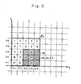
- Figure 5 presents this situation in expanded form. Identifying the enclosed pixels from left to right beginning at the upper left corner, and letting all image-intensity values be unity, yields the following relations:
- CENPROCESS is a FORTRAN-language realization of the essential steps of the invention.
- FORTRAN subroutines PEAKDETECT and HIGHPASS are a realization of the centroid-count interrogation process, while HIGHPASS performs pedestal removal in accordance with the second of the removal techniques described previously.
- the REFPOINTS output of the PEAKDETECT subroutine will be the determined locations of small targets. In an actual operational situation, these location designations would then be made available for further track processing.
- routines as set forth are merely exemplary.
Landscapes
- Engineering & Computer Science (AREA)
- Physics & Mathematics (AREA)
- General Physics & Mathematics (AREA)
- Theoretical Computer Science (AREA)
- Multimedia (AREA)
- Computer Vision & Pattern Recognition (AREA)
- Nonlinear Science (AREA)
- Image Analysis (AREA)
- Control Of Position Or Direction (AREA)
- Testing Of Balance (AREA)
Abstract
Description
- The invention relates in general to image processing and in particular to a technique for locating small objects in a given field of view.
- It is an aim of this invention to provide an image-analysis technique which is capable of ascertaining both the presence and location of small objects in an entire-scene image.
- It is also an aim of this invention to provide a technique which is capable of performing such determinations efficiently in real-time.
- It is a further aim of this invention to provide a technique which continues to provide these determination capabilities even with respect to a wide variety of objects, image conditions and image content.
- These and other aims are achieved by the disclosed invention which in one of its aspects causes a processing window to be step-wise scanned over a sensed, pixel-based image, with the centroid pixel of each set of image data successively contained within the scanning window being determined, and with a tabulation being made of the number of times each image pixel is thusly determined to be the windowed-data centroid. As a net result, those pixels having the higher tabulated centroid counts will be the intra-image locations of small objects contained within the scene.
- These and other aims and advantages will become apparent from a study of the following specification when considered in conjunction with the accompanying drawings in which:
- Figure 1 shows in simplified schematic form an example image in which the location of any small objects is to be determined;
- Figure 2 illustrates the concept of the scanning analysis window which is shifted in single-pixel steps horizontally and vertically over the sensed image, as is required in accordance with the invention;
- In Figure 3 is presented the structure and double-pixel scan procedure of a filtering window used for background elimination;
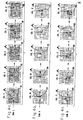
- The three rows of image sections respectively presented in Figures 4a, 4b and 4c show a sequence of successive horizontal window positions as the analysis window scans over the three objects which appear in the image of Figure 1;
- Figure 5 illustrates various aspects of a windowed-data centroiding calculation;
- In Figure 6 is displayed a generalized flow chart of an example computer program which implements the basic centroid-accumulation technique of the present invention.
- In Figure 1 is presented in simplified schematic form an example sensed
image 100 such as may be obtained from a given field of view by means of conventional sensing and imaging devices. Within this scene appear the large, intermediate, and small-sized objects, respectively consisting offactory 110,house 120 andautomobile 130. The basic purpose of the invention is to automatically determine whether small objects are present in the sensed scene and, if so, what their intra-scene locations are. With respect to the objects appearing inimage 100, it is thus generally desired to ascertain the presence of, as well as the location of,automobile 130, while distinguishing the large-sized factory 110 and the intermediately-sizedhouse 120. - (It may be noted parenthetically that the schematic objects of the simplified scene will be regarded both as being isolated bright spots of uniform, unit-value image intensity and as being surrounded by a zero-intensity background.)
- As is well known, images such as
scene 100 are typically composed of a plurality of picture elements called pixels, with the component pixels being arranged into a plurality of lines, and with each line being in turn composed of a plurality of pixels. Inimage 100, these lines are labeled as rows Rl through R20, each of which has 20 pixels. Similarly-situated pixels in the successive lines form columns Cl through C20. Any of the individual pixels inimage 100 may then be conveniently identified by a unique row and column designation. For example,automobile 130 may be seen to be located at the intersection pixel ofrow 9 andcolumn 16. This pixel is given the symbolic designation of {R9, Cl6}. - Shown superimposed on a portion of
scene 100 is processing window Wx. In practicing the invention, window Wx is typically scanned over the entire image in a raster-like, step-wise combination of single-column and single-row increments. At each window position, a determination is made as to which of the enclosed pixels coincides with the centroid of whatever objects (i.e., image data) or portions of objects are contained there within the window. - For example, with window Wx in its depicted position enclosing the 5-p.ixel-by-5-pixel array of pixels {R2, C10} through {R2, C14} to {R6, C10} through {R6, C14}, the factory-110 segment which occupies the column-10 pixels from R2 through R6 falls within the window. It may readily be demonstrated that the centroid of this window-enclosed object segment coincides with image pixel {R4, C10}.
- Following this ascertainment of the centroid pixel, a centroid count for the ascertained pixel is incremented in an accumulating count-storage array whose purpose is to tabulate the number of times each pixel in the image has been determined to be a data centroid of the scanning window. Because a separate count must be kept for each of the pixels, the utilized tabulation array will generally have as many count-storage elements as there are pixels in the image being analyzed. Thus with respect to the factory-segment example begun above, the centroid processing at the Wx window position as shown in Figure 1 would result in a centroid count increment for the storage element corresponding to pixel {R4, C10}.
- As will be further described below, once the window has been scanned over the entire image and the resulting per-window-position centroid locations have been determined and accumulated, the pixels corresponding to those count-array positions having high count- accumulations will be the intra-image locations of small-sized objects.
- With reference to Figure 2, fundamental aspects of the invention will now be further discussed.
- The more-specific nature of the processing window may be better understood by examining the means conventionally utilized for assembling a composite scene such as
image 100. Typically, the sensed scene- data of individual pixels is read into a storage array which has an individual and unique storage position for the data of each pixel in the image. A statement that the processing window has been placed at a given position in the image may be regarded as being in the nature of a term of art which refers to the more concrete operation of utilizing gating networks to read out of memory the ordered image data for each one of that set of pixels which is enclosed within the perimeter of the window as positioned. The ensuing processing is then performed on that data set as a unit. - Consider, for example, the situation presented in Figure 2. The figure shows the processing window in the vicinity of the
small automobile target 130 which appears inimage 100 of Figure 1. Designated as "Wjk" is the window located in position "jk," where "j" is a generalized index related to the particular set of rows at which the window is positioned, while "k" is the analogous index with respect to the associated columns. For Wjk as shown, the subject rows are seen to be R6 through R10, while the associated columns are C13 through C17. The windowing of this set of rows and columns means that there will be read out of the image-data memory the ordered contents of those storage positions which hold the image-data values of pixels {R6, C13} through {R6, C171 to {R10, C13} through {R10, C17). The centroiding operation which then follows is performed with respect to the data values of this windowed/memory-gated set of pixels. - In generalizing the description of the size of a given processing window, it becomes convenient to specify the window's width and height as respectively being M and N pixels in extent. In an actual operational environment, the sizing dimensions M and N would be tailored according to several considerations.
- The first consideration is that of the relative size of a small object of interest as it may be expected to appear within a sensed scene. Intra-scene size is an important window-sizing consideration as an inherent consequence of the nature of the inventive-object-location technique. It will become apparent from example scene- analysis situations presented below that the subject technique may be regarded as being of enhanced effectiveness with respect to objects whose intra-scene size is smaller than about M/2 by N/2. Furthermore, it will likewise become apparent that in general the greater the differential between the (M/2)-by-(N/2) window area and the intra-scene area of a desired object, the more pronounced the small-size-location capability will become.
- As is well known, intra-scene size will be a function not only of the desired object's absolute size but also of sensor-versus-scene geometry. In addition to optics and imaging mechanics, the distance between the sensor and the sensed scene is a principal element of the sensor-versus-scene geometry and is hence a factor which has an important effect on a desired object's intra-scene size. Furthermore, in dynamic operational situations where there is expected to be relative motion between the sensor and the scene, the window dimensions would during the course of operation (although not during the processing of a given single scene) be adaptively adjusted to accommodate the consequentially-varying size of the type of object to be detected. It will be apparent that the window may also be dynamically altered where at different times it is desired to locate different types of objects having among themselves different relative sizes.
- The second of the considerations which can have an important influence on window dimensioning is the desired object's perceived shape. If a given object is likely to have a known, fixed orientation and will be perceived from the perspective of the sensor as being generally rectangular as opposed to either square or circular, a rectangular window may prove to be more appropriate to the achievement of the desired size discrimination than simply a square window of the type utilized for illustrative purposes throughout this specification. Thus with reference to the above discussion concerning the invention's often maximal effectiveness with respect to targets whose intra-scene size is less than about M/2 by N/2 in the case of an M-by-N window, it becomes possible, in many situations involving rectangular, fixed-orientation objects of image size R by S, to specify that the optimum window size be at least 2R by 2S.
- In many operational situations, however, it will not be sufficient to adjust window dimensions solely according to a given object's scene size. In addition, therefore, to the above-discussed window-sizing factors, there at times exist countervailing considerations which limit the extent to which the inventive size- discrimination capability may be optimized through dimensional increases for the purpose of obtaining the largest possible differential between window area and an object's occupied scene area.
- A first set of countervailing considerations may be given the generic designation of "clutter." The general problem here is that the presence within the window of extraneous imagery will tend to adversely affect the ability of the required intra-window centroiding operation to focus on even a small object of interest. This type of clutter includes the situations where enclosed within the window at a given position are either more than one small target or portions of larger objects in addition to an object of interest.
- A second set of countervailing considerations is related to the processing capabilities of the hardware system which would typically be utilized to practice the inventive method in an actual operational environment. The desire to minimize execution times or computational storage requirements may provide another group of factors which limit window size as a consequence of a desire to limit the amount of pixel data which may advantageously be included in each of the required centroiding calculations.
- It is thus apparent that in many practical operational situations of interest, window dimensional optimization is simply a matter for empirical determination in light of not only the objects of interest and the nature of the scene to be viewed, but also of the equipment utilized for both image sensing and data analysis.
- It has been generally stated that the practice of the inventive method requires that the processing window be step-wise scanned over the entire sensed image. This general scanning requirement may be more specifically stated in terms of a collection of M-by-N windowed pixel sets upon which the likewise-required centroiding is performed. The more-specifically-stated requirement, as applied within each one of whatever image sectors are to be examined for the presence of small objects, is that each possible M-by-N grouping of the given sector's pixels must be subjected to the centroiding operation.
- One convenient procedure for fulfilling this requirement in a systematic fashion is to scan the window according to row-by-row increments, with a cross-scene column-by-column scan being performed along each row position. The mechanics of this scan procedure may be better understood with reference to Figure 2. As explained previously, the solid-perimetered window designated Wjk relates to the currently-processed 5-by-5 pixel set of the pixels from rows R6 through R10 and columns C13 through C17, with the indices "j" and "k" respectively designating in a general way the particular set of rows and columns of that window. Once the Wjk pixel set has been centroided, according to the procedures to be more fully described below, the pixel set of the window Wj(k+l) is then processed. In other words, with the row group being held constant, the window is right-shifted by one column, with the R6 through R10 pixels of
column 17 being utilized in the new centroiding computation in place of the R6 through R10 pixels of column 13. The single-column right-shift continues until the right edge of the scene is reached, at which point the processing is then carried on with a single-row down-shifted sequence of windows referenced with respect to the R7-through-Rll row set. W(j+1)k, with its incremented row index (j+1), shows the row- incremented window as it once again moves into the vicinity of thesmall target 130. - The shift sequence typically begins at the first available M-by-N cluster of pixels in the upper left corner of the image where the single-column right-shifting is performed across the entire scene with respect to the first available set of N rows. The processing then continues through the successive row-increment-plus- column-shift sequences until all of the M-by-N pixel clusters of all of the scene portions of interest have been centroided. It may be noted that in the typically- employed scan sequencing, the window is not allowed to overlap the edges of the scene. Near scene boundaries, therefore, the centroiding is thus typically performed only with respect to window positions in which a full complement of M-by-N pixels is available.
- As utilized in the image-analysis context of this invention, the conventional mathematical operation of centroiding becomes a determination of that point within each window position which may be regarded as being in the nature of an effective center of the image intensities enclosed by the given window. In the practice of the invention, this effective center is not only very useful in terms of the net results achieved by the invention itself, but is also especially expedient in facilitating the achievement of these results. The centroid's usefulness is apparent in those operational environments where a principal processing objective is the ascertainment, for each small object in the sensed scene, of a single pixel which may be taken as being representative of the intra-image location of that object. The centroid's expediency follows from a consequential property which contributes significantly to the conceptual basis of the inventive method. This property is the tendency of the centroid of those objects which are significantly smaller-than the window size, as distinguished from those whose size is of the same order as or larger than the window, to remain stationary while the window is being moved through a sequential plurality of step-wise-incremented positions. It is this stationarity property, further clarified in examples to be presented below, which is a major factor in bringing about the accumulation effect used as the final indicator of the possible presence and resulting location of any small point object in the scene.
- As is readily-apparent from the standard-form centroiding equations presented below, and as is to be expected in the performance of a mathematical operation whose purpose is to ascertain an effective image-intensity center, the centroid calculation requires as inputs two quantities for each pixel:
- (1) a measure of the pixel's displacement with respect to some frame of reference, and
- (2) an indicator of image intensity within the given pixel.
- It has been found that because of several unique characteristics of certain image-processing environments in which the invention may be practiced, measures and indicators of a specially-adapted nature yield preferred inventive performance. In order to facilitate a clearer understanding of the manner in which the conventional centroiding equations are typically utilized in the practice of the present invention with respect to these particularized environments, the specially-adapted form of both the displacement measures and the image-intensity indicators will now be examined prior to the formal presentation below of the operationally-utilized centroiding equations themselves..
- In the practice of the present invention, it may readily be demonstrated that the frame of reference used for centroiding-related displacement measurements is arbitrary as long as there is reference- frame consistency from one centroid computation to the next and hence from one window position to the next. Simply employing a Cartesian coordinate system in which the row and column designators become the respective (x,y) units of displacement measurement is both sufficient and straightforward. However, in various processing situations where hardware economies and computational efficiencies are of significant concern, it has been found preferable to provide the processing window with a localized Cartesian system which is carried along with the window throughout its scene scan.
- Window Wjk of Figure 2 may thus be seen to contain a coordinate system of this nature. For illustrative convenience, the lower left-hand corner is designated the origin. The ordinal designators of the 1st through Mth columns and 1st through Nth rows become respectively the x and y units which are to be used in the associated centroid calculation.
- It may be noted that because the window position is always known, it is always possible to transform a locally-determined centroid into a centroid which is properly positioned with respect to a more-general row-and-column-referenced coordinate system. Thus once again with respect to the Figure-2 situation, pixel (Rll, C12) may be regarded as an origin for window Wjk. As it may be demonstrated that the localized coordinates of this window's image-data centroid are at x=4 and y=2, the global coordinates and hence intra-image row and column designations could be obtained by a simple alteration of the row and column designators of the origin pixel according to the respective local y and x values. Thus, subtracting y=2 from Rll while adding x=4 to C12 yields {R9, C161 as the correct global centroid location for the Wjk image data.
- In addition to the utilization of specially-adapted displacement measures, the centroid calculations in a specialized class of operating environments also typically employ image-intensities which are adjusted so as to cause the computational results to become more-meaningful representations of the associated windows' intensity centers. The need for the intensity adjustments is a consequence of an operationally-adverse interaction between, on one hand, the nature of the centroid calculations themselves and, on the other, the nature of the image data presented for inventive processing in these specialized operational situations.
- A particular problem situation often presented is that in which a desired small object, by itself yielding a sensed image intensity of a given level, is observed while effectively superimposed on a field-of-view background having its own, nonzero image-intensity level. When this is the case, the background is said to form a "pedestal" upon which the object rests. With respect to such situations, it may readily be demonstrated that there is a computational tendency for the small object to become in a sense "obscured" by its background and for the resulting inventive processing to be less effective in ascertaining if not the presence of such an object, then at least its true image centroid. It was determined to be of considerable benefit, therefore, to subject the sensed scene in its "raw" form to a type of pre-processing designed in its basic effect to remove the pedestals by reducing any extensive, nonzero backgrounds to a zero intensity level. Within the context of this invention, this background-reduction process will be given the generic designation of image-data normalization.
- It may be further noted that in those situations where the intensity of the background is not only nonzero but also not significantly different from that of a given, superimposed small object, it may be advantageous to either disregard such noncontrasting targets by thresholding the de-pedestalled image data or artificially intensifying them by means of a post-pedestal-removal image enhancement.
- Several techniques have been devised to perform the data-normalizing pedestal removal. Before describing these techniques in greater detail, some general comments will be made concerning the basic approach to data- normalization in accordance with which the techniques were formulated.
- In general, the process of pedestal removal by reducing background intensity to zero is typically achieved in a relatively simple manner by determining an average intensity value within a given area and then reducing all "raw" intensity values within that area by this determined average amount. With respect to the windowing typically performed in the practice of this invention, where the centroiding is carried out only with respect to a localized group of pixels, it becomes apparent, once the need for pedestal-removal is recognized, that the removal must be done on a basis which is localized to the particular cluster of pixels which are being analyzed for the presence of small objects and hence which are included in a given centroiding computation. Thus the averaging by which background reduction is typically achieved should, for the purposes of optimizing inventive performance, be performed on the basis of only those intensity values which are sensed in the immediate vicinity of a given subject pixel. In recognition of these characteristics of the processing situation at hand, the pedestal removal and hence average-level determination is performed on a windowed set of pixels.
- Two actual pedestal-removal techniques will be described further. It will become apparent that both effectuate the basic processing goal of data-normalizing pedestal-removal, just as it will become apparent that both ultimately perform this pedestal removal on a localized, windowed-pixel-set basis. However, although in a general sense it will in addition become apparent that both also share the processing-cycle characteristic of being applied prior to the point at which the image-intensity values are included in the actual centroid computations, the techniques are nevertheless distinguishable in significant part on the basis of more precisely where in the image-processing cycle they are utilized. In one of the techniques, the pedestal removal is done at the time each centroiding window is formed and hence on a separate and individual basis immediately prior to each centroiding calculation. In the other of the techniques, the pedestal removal is carried out with respect to all of the subject pixels prior to any scene centroiding. The centroiding calculations which then follow are performed with respect an entire scene of de-pedestalled data.
- Thus, in its specifics, the centroid-by- centroid process of the first pedestal-removal technique involves the following: Each time the basic processing window is incremented to a new position and thus encloses a new set of pixels, the actual centroid calculation itself is not performed until a determination has been made of what is the average intensity level of all of the applied "raw" levels of each of the pixels in that given set. In a centroid-calculation memory, the "raw" intensity value of each pixel is reduced by the determined average. (It may be noted that the presented image values of the pixels enclosed by the window in its given position are themselves left unaltered for the sake of the averaging calculations which are then subsequently performed when the centroiding window shifts to its next succeeding position.) The centroid calculation for that one window then proceeds on the basis of the reduced intensity values. Once that window's centroiding is completed, the window is shifted to enclose a new set of pixels where the centroiding operation is again preceded by an associated average-level determination performed with respect to applied intensity values only.
- In turning to the specifics of the second of the pedestal-removal techniques, it should be noted at the outset that the primary motivations for the development and utilization of this technique, in its to- be-specified form, were hardware economy and processing efficiency. It should be noted in addition that although this particular technique will be designated the preferred procedure, the technique is preferred simply because, in one operational situation where the objectives of hardware economy and processing efficiency were controlling considerations, the technique provided a means of readily achieving these goals given inherent limitations of the processing environment and the equipment available.
- Thus, in the one operational situation where this second technique was actually implemented, the dual aims of hardware economy and processing efficiency proved to be most readily facilitated by the use of an averaging window possessing a format the same as that of the averaging window Wav which appears in Figure 3. Wav is seen to be eight pixels in width and four pixels in height, while generally being composed of an
outer averaging window 350a and an inner image-reduction window 350b. - The averaging window was and may be utilized as follows with respect to an actual image: The window is step-wise scanned over the entire image of interest in a manner similar to that in which the basic centroiding window is scanned over the scene. In the interests of processing efficiency, however, acceptable intensity- reduction performance is achieved by moving the window in increments of two columns and then two rows at a time, instead of the single-unit increments utilized for centroiding. At each window position, the average level of all the applied intensity data values for the thirty-two pixels enclosed by
outer window 350a is determined. The intensity values which result from the process of subtracting this determined average from the "raw" intensity values of each of the four pixels enclosed by theinner window 350b are then stored in a working array having storage positions equal in number to, and uniquely corresponding to, those of the image array. In a manner analogous to that of the first of the pedestal-removal techniques, the presented image values of the pixels enclosed by the inner window are themselves left unaltered for the sake of the averaging calculations which are then subsequently performed when the averaging window shifts to its next succeeding position. The rationale for the double-column and double-row steps of the outer window is apparent from the four-pixel nature of the inner window. - Once the entire "raw" image is averaged and reduced in this fashion, the basic centroiding itself is then performed by scanning the centroiding window over the reduced image now held in the working storage. It may be seen that when pre-centroiding pedestal-removal is performed in this fashion, the nonreduced image values of those pixels near the periphery of the original image are ignored in the ultimate centroiding operation.
- The mathematical equations utilized to carry out the centroiding operations may typically take the following conventional forms:


- In these equations:
- (a) the indicated summations are performed over all pixels of that set which is currently enclosed by the centroiding window in a given position;
- (b) Ir = image intensity of the rth pixel of the enclosed set;
- (c) xr = the rth pixel's horizontal displacement within the localized intra-window coordinate system explained above;
- (d) yr = the vertical distance within the localized intra-window coordinate system;
- (e)
X ℓ = the localized intra-window horizontal location of the centroid pixel; and - (f) Yt = the localized intra-window vertical location of the centroid pixel.
- As mentioned previously, the local centroid designation {
X ℓ,Y ℓ} may then through well-known coordinate-transformation techniques be readily converted into a global row and column designation for that one, overall-scene pixel which has been determined in this fashion to be the centroid of the data currently contained within the window. - In those specialized imaging situations where the data may be expected to occur superimposed on pedestals as described above, the Ir quantity may be more precisely defined in terms of the two pedestal-removal techniques as follows:
- (1) Where the first, individualized pedestal-removal technique is utilized, Ir may typically be obtained through the following relations:

- (a) max[a, b] = "maximum-of" function = a when a ≥ b = b when a < b
- (b) Irq = sensed, raw image intensity at the rth pixel; and
- (c) µ = the average intensity level computed at the given window position.
- It may be seen, especially in view of the principal desire to reduce the background intensity to zero, that it is sufficient to assign Ir the value 0 when the quantity (Irq-u) yields a negative value.
- (2) When the second, globally-executed pedestal-reduction technique is used, Ir is simply the reduced intensity value obtained from the appropriate position of the working storage array. It may be noted that in the performance of this reduction, a zero- thresholding "maximum-of" function, described above and also incorporated in the example subroutine HIGHPASS presented below, would typically be employed.
- It may be observed that if every intensity value in a given image is multiplied by some constant K and/or increased or decreased through the addition of some constant K, the centroiding calculation (together with any pedestal removal) will be unaffected. An important consequential property of the invention is that the detection and location of small objects may be achieved without having to know the gain or DC offset of the sensor which produced the image.
- As indicated previously, the net outcome of each of the centroiding calculations is an incrementing of a centroid count for that intra-scene pixel determined to coincide with the current intra-window centroid. After the completion of all of the given scene's centroiding operations, the conventional accumulation array utilized for holding the resulting pixel-by-pixel centroid counts as finally incremented may be interrogated by means of various memory-inventory techniques. Because smaller objects will tend to have given rise to the larger of such centroid counts, the pixels corresponding to those accumulation-array storage positions found during the course of the interrogation to have high counts will in accordance with the invention be deemed to be the intra-scene locations of small point targets.
- Accumulation-array interrogation is the process of examining the array's tabulated contents for those high centroid counts which indicate the presence of a small object at the associated pixel. Among the effectively- equivalent specific procedures which may be utilized to carry out this interrogation process are what will be designated as peak-count detection and count thresholding.
- In peak-count detection the accumulation array is simply checked to see which of its tabulated centroid counts is the highest. The associated pixel is then designated as being the intra-scene location of a small target. To ascertain the presence of any additional small targets within the given scene, the peak detection may be performed iteratively by first, reducing to zero the count of the array position having the first-detected peak; second, re-examining the array contents for a second peak; third, location- designating the second-detected peak; and then repeating the peak-nullification, contents-re-examination and location-designation sequence.
- As its name implies, count-thresholding is the related interrogation procedure in which the accumulation array is checked not for that one count which is higher than the rest but for those counts which are higher than some threshold. This procedure follows from the observation that, in many operational situations of interest, desired small targets will tend to give rise to centroid counts of at least a certain level. In such situations it may then be possible to establish a centroid-count threshold and to declare that whenever in the course of an accumulation-array interrogation a count is found to exceed this threshold, the count will be taken as an indication of the presence of a small target. It will at times also be possible to analogously ascertain an intermediate range of centroid counts which may be used as indicators of objects of intermediate size.
- Such thresholds will typically tend to be quantities which can be determined on an empirical basis only and will be dependent upon the unique characteristics of the given processing situation at hand. Relevant considerations to be evaluated in setting the thresholds will include the size of the centroiding window, the expected size of the objects of interest, the expected concentration of objects, and the extent to which extraneous "clutter" may be expected to be enclosed along with an object of interest by the centroiding window in any one of its positions.
- Consider, for example, the situation presented in Figure 1 with respect to
automobile 130 and centroiding window Wx. Given the window size of 5-by-5 (i.e., 25 pixels), and an object size of a single pixel, it will be apparent that as the window scans in the vicinity of this object, the car will be contained within the window for a total of 25 window positions. Furthermore, given the solitary location of this particular object and the clutter-free nature of the presented scene, it will also be apparent that pixel {R9, C16} will achieve a centroid count of a full 25. In an analogous fashion, the center pixel {R16, C131 ofhouse 120 will be demonstrated to achieve a centroid count of 16. Thus, in situations where a 5-by-5 window is used with respect to single-pixel objects which tend to occur in clutter-free isolation, and where the next-largest object occupies a 9-pixel square, a count threshold of 20 may be sufficient for small-object-location purposes. - It may be noted that as between peak-detection and count-thresholding, the count-thresholding procedure has been found in some situations to be a more operationally-efficient means of realizing array interrogation.
- In each portion of Figure 4 is presented 5 of the successive column-incremented window positions resulting when the 5-by-5 centroiding window Wx of Figure 1 scans, along the Figure-1 designated row-groups "a," "b" and "c," in the vicinity of the three objects shown in
scene 100. In sequence "a" it may be seen that the size characteristics of the factory are such that at each of its successive positions, the window is completely filled by the object. In a situation such as this, where the image Intensity is taken to be uniform, the centroid of the image data contained within the window is the same as the center of the window itself. As the window moves, its center will, of course, move along with it. Consequentially, each member of the indicted sequence of pixels {R5, C4) through {R5, C8} will be coincident with the window center just once and hence will have its associated centroid count incremented only once. - An opposite situation is shown in sequence "b" where the single-
pixel object 130 is entirely enclosed by the window at each of the 5 successive positions. With the only image data being that of a single-pixeled object, the windowed-data centroid is simply the pixel in which that object is located. Pixel {R9, C16} will, therefore, in all 5 window positions be ascertained to be the pixel which coincides with the centroid of the image data contained within the centroiding window. As a result, pixel {R9, C16} will have its centroid count incremented 5 times for this window sequence. - An intermediate situation is shown in sequence "c" where the intermediately-
sized house 120 is seen to be completely contained within the window in three of its successive positions while being only partially contained within the window in two of its positions. Thus, although {R16, C131 will be correctly ascertained as the centroid-coincident pixel 3 times, pixel {Rl6, C14} will be chosen twice. - It may be observed here that the double centroid count for the identified second pixel was obtained in part through the use of a processing convention in which that pixel to the right of and, if necessary, one row up from an ambiguous centroid location is deemed to be the centroid location in those situations where the strict results obtained by the centroiding calculations will place the centroid on a junction between adjacent pixels. Alternative but analogous ambiguity-resolution conventions are readily apparent. For example, in one actual realization the ambiguities took the form of fractional remainders following the divisions by ∑Ir. The preferred manner of dealing with such remainders was to simply truncate them. With the preferred, intra-window localized coordinate system being in that situation one in which the origin was at the upper-left corner of the window, the resolution- by-truncation caused that pixel which was to the left of and, if necessary, above the true centroid position to be deemed the centroid location.
- An actual centroid calculation will be performed in the context of the first of the window positions in the "c" sequence of Figure 4. The specific situation examined will be that of window lWx. It is apparent that as a result of the simple, clutter-free nature of the example image, pedestal removal will not be necessary.
- Figure 5 presents this situation in expanded form. Identifying the enclosed pixels from left to right beginning at the upper left corner, and letting all image-intensity values be unity, yields the following relations:


- Thus,
X ℓ=4 andY ℓ=2, which may be seen to coincide with the center ofhouse 120 and which may further be seen to be transformable into a final centroid pixel designation of {R16, C13}. - The following Table presents the complete results of utilizing a 5-by-5 centroiding window to perform the inventive method upon the example image of
scene 100. (The above-noted right-and-up convention regarding pixel selection in cases of ambiguous centroids is incorporated into these results.)


- Implementing the above-described inventive method in computer-program form is regarded as a relatively straightforward matter well within the ordinary skill of the art. Nevertheless, there is generally flowcharted in the principal portion of Figure 6 and listed below the computer subroutine CENPROCESS which is a FORTRAN-language realization of the essential steps of the invention. Listed in addition are the FORTRAN subroutines PEAKDETECT and HIGHPASS, as well as an associated Executive routine. PEAKDETECT is a realization of the centroid-count interrogation process, while HIGHPASS performs pedestal removal in accordance with the second of the removal techniques described previously. The REFPOINTS output of the PEAKDETECT subroutine will be the determined locations of small targets. In an actual operational situation, these location designations would then be made available for further track processing.
- It will be apparent that the listed routines were tailored in accordance with the requirements of a particular operational situation. It will similarly be apparent that the diverse constraints of the various alternative environments in which it is desired to practice the invention may necessitate program adaptations in order to achieve optimized operationality in those environments. It is to be understood, therefore, that the routines as set forth are merely exemplary.


Claims (5)
whereby those pixels having the
higher tabulated centroid counts are the locations of smaller-dimensioned objects in the scene.
Applications Claiming Priority (2)
| Application Number | Priority Date | Filing Date | Title |
|---|---|---|---|
| US363318 | 1982-03-29 | ||
| US06/363,318 US4499597A (en) | 1982-03-29 | 1982-03-29 | Small-object location utilizing centroid accumulation |
Publications (3)
| Publication Number | Publication Date |
|---|---|
| EP0090159A2 true EP0090159A2 (en) | 1983-10-05 |
| EP0090159A3 EP0090159A3 (en) | 1984-11-14 |
| EP0090159B1 EP0090159B1 (en) | 1987-12-02 |
Family
ID=23429731
Family Applications (1)
| Application Number | Title | Priority Date | Filing Date |
|---|---|---|---|
| EP83101380A Expired EP0090159B1 (en) | 1982-03-29 | 1983-02-14 | Small-object location utilizing centroid accumulation |
Country Status (5)
| Country | Link |
|---|---|
| US (1) | US4499597A (en) |
| EP (1) | EP0090159B1 (en) |
| JP (1) | JPS5916023A (en) |
| DE (2) | DE3374818D1 (en) |
| IL (1) | IL67821A (en) |
Families Citing this family (30)
| Publication number | Priority date | Publication date | Assignee | Title |
|---|---|---|---|---|
| US4783829A (en) * | 1983-02-23 | 1988-11-08 | Hitachi, Ltd. | Pattern recognition apparatus |
| US4550432A (en) * | 1983-04-13 | 1985-10-29 | At&T Bell Laboratories | Image processor using a moment generator |
| US4637052A (en) * | 1983-10-24 | 1987-01-13 | The United States Of America As Represented By The Department Of Energy | Method and apparatus for enhancing microchannel plate data |
| US4571635A (en) * | 1984-02-17 | 1986-02-18 | Minnesota Mining And Manufacturing Company | Method of image enhancement by raster scanning |
| US4628534A (en) * | 1984-07-06 | 1986-12-09 | Honeywell Information Systems Inc. | Method for changing the resolution of compressed image data |
| JPH0778823B2 (en) * | 1985-12-09 | 1995-08-23 | 株式会社応用計測研究所 | Image processing method |
| US4760247A (en) * | 1986-04-04 | 1988-07-26 | Bally Manufacturing Company | Optical card reader utilizing area image processing |
| JPS62267610A (en) * | 1986-05-16 | 1987-11-20 | Fuji Electric Co Ltd | Detecting system for rotational angle of object pattern |
| JPH0810132B2 (en) * | 1986-06-04 | 1996-01-31 | 富士電機株式会社 | Target pattern rotation angle detection method |
| US4907152A (en) * | 1986-09-25 | 1990-03-06 | The Boeing Company | Method of improving CT resolution |
| US4955062A (en) * | 1986-12-10 | 1990-09-04 | Canon Kabushiki Kaisha | Pattern detecting method and apparatus |
| US4797806A (en) * | 1987-02-19 | 1989-01-10 | Gtx Corporation | High speed serial pixel neighborhood processor and method |
| US4821336A (en) * | 1987-02-19 | 1989-04-11 | Gtx Corporation | Method and apparatus for simplifying runlength data from scanning of images |
| DE3708795C2 (en) * | 1987-03-18 | 1995-08-03 | Gsf Forschungszentrum Umwelt | Process for size selection in real-time video |
| US4939672A (en) * | 1987-11-09 | 1990-07-03 | Tektronix, Inc. | Method and apparatus for classifying graphics segments to facilitate pick and display operation |
| FR2625396B1 (en) * | 1987-12-23 | 1990-06-01 | Europ Agence Spatiale | METHOD AND DEVICE FOR DETERMINING THE POSITION OF THE CENTER OF A LIGHT SIGNAL RECEIVED IN A CHARGE-COUPLED MOSAIC DETECTOR |
| US4969200A (en) * | 1988-03-25 | 1990-11-06 | Texas Instruments Incorporated | Target autoalignment for pattern inspector or writer |
| US4991092A (en) * | 1988-08-12 | 1991-02-05 | The Regents Of The University Of California | Image processor for enhancing contrast between subregions of a region of interest |
| US5187777A (en) * | 1989-09-21 | 1993-02-16 | Loral Aerospace Corp. | Multi-function pre-processor for target tracking |
| US5164994A (en) * | 1989-12-21 | 1992-11-17 | Hughes Aircraft Company | Solder joint locator |
| GB9102713D0 (en) * | 1991-02-08 | 1991-03-27 | Univ London | Centroiding method for photon counting detectors |
| US5731539A (en) * | 1992-10-02 | 1998-03-24 | Motorola, Inc. | Target detection method |
| US5455899A (en) * | 1992-12-31 | 1995-10-03 | International Business Machines Corporation | High speed image data processing circuit |
| US5479526A (en) * | 1993-03-23 | 1995-12-26 | Martin Marietta | Pixel designator for small objects |
| JP3433983B2 (en) * | 1993-09-20 | 2003-08-04 | 株式会社日立製作所 | Image reduction apparatus and image reduction method |
| JPH0841778A (en) * | 1994-08-01 | 1996-02-13 | Kanebo Ltd | Cloth gigger |
| IT1274405B (en) * | 1995-04-28 | 1997-07-17 | San Raffaele Centro Fond | AUTOMATIC MICROSCOPE HEAD POSITIONING AND CENTERING DEVICE |
| DE19528465C2 (en) * | 1995-08-03 | 2000-07-06 | Leica Geosystems Ag | Method and device for quickly detecting the position of a target |
| US9129185B1 (en) * | 2012-05-21 | 2015-09-08 | The Boeing Company | System and method for reducing image clutter |
| CN115205369B (en) * | 2022-08-03 | 2024-04-02 | 江苏科技大学 | Anti-atmospheric turbulence lamp target image displacement extraction algorithm |
Citations (2)
| Publication number | Priority date | Publication date | Assignee | Title |
|---|---|---|---|---|
| US3829614A (en) * | 1970-02-11 | 1974-08-13 | Saab Scania Ab | Automatic video contrast tracker |
| US4298858A (en) * | 1980-03-27 | 1981-11-03 | The United States Of America As Represented By The Secretary Of The Air Force | Method and apparatus for augmenting binary patterns |
Family Cites Families (3)
| Publication number | Priority date | Publication date | Assignee | Title |
|---|---|---|---|---|
| US3292148A (en) * | 1961-05-08 | 1966-12-13 | Little Inc A | Character recognition apparatus using two-dimensional density functions |
| US3274549A (en) * | 1962-05-04 | 1966-09-20 | Kollsman Instr Corp | Automatic pattern recognition system |
| US4398256A (en) * | 1981-03-16 | 1983-08-09 | Hughes Aircraft Company | Image processing architecture |
-
1982
- 1982-03-29 US US06/363,318 patent/US4499597A/en not_active Expired - Lifetime
-
1983
- 1983-02-01 IL IL67821A patent/IL67821A/en not_active IP Right Cessation
- 1983-02-14 EP EP83101380A patent/EP0090159B1/en not_active Expired
- 1983-02-14 DE DE8383101380T patent/DE3374818D1/en not_active Expired
- 1983-02-14 DE DE198383101380T patent/DE90159T1/en active Pending
- 1983-03-29 JP JP58051731A patent/JPS5916023A/en active Granted
Patent Citations (2)
| Publication number | Priority date | Publication date | Assignee | Title |
|---|---|---|---|---|
| US3829614A (en) * | 1970-02-11 | 1974-08-13 | Saab Scania Ab | Automatic video contrast tracker |
| US4298858A (en) * | 1980-03-27 | 1981-11-03 | The United States Of America As Represented By The Secretary Of The Air Force | Method and apparatus for augmenting binary patterns |
Non-Patent Citations (2)
| Title |
|---|
| IEEE TRANSACTIONS ON ELECTRONIC COMPUTERS, vol. EC-12, no. 3, June 1963, pages 251-262, New York, USA; J.K. HAWKINS et al.: "A parallel computer organization and mechanizations" * |
| PROCEEDINGS OF THE FOURTH INTERNATIONAL JOINT CONFERENCE ON PATTERN RECOGNITION, 7th-10th November 1978, pages 774-779, Kyoto, JP; L.M. RUBIN et al.: "Automatic target cueing" * |
Also Published As
| Publication number | Publication date |
|---|---|
| US4499597A (en) | 1985-02-12 |
| DE3374818D1 (en) | 1988-01-14 |
| JPH05749B2 (en) | 1993-01-06 |
| IL67821A (en) | 1986-11-30 |
| EP0090159A3 (en) | 1984-11-14 |
| DE90159T1 (en) | 1984-04-12 |
| JPS5916023A (en) | 1984-01-27 |
| EP0090159B1 (en) | 1987-12-02 |
Similar Documents
| Publication | Publication Date | Title |
|---|---|---|
| EP0090159B1 (en) | Small-object location utilizing centroid accumulation | |
| US5870494A (en) | Method for determining orientation of contour line segment in local area and for determining straight line and corner | |
| US5073958A (en) | Method of detecting edges in images | |
| US7953265B2 (en) | Method and system for automatic algorithm selection for segmenting lesions on pet images | |
| US4736439A (en) | Image preprocessing by modified median filter | |
| US5034969A (en) | Tomographic image diagnostic method and apparatus including automatic ROI setting means | |
| US5170347A (en) | System to reformat images for three-dimensional display using unique spatial encoding and non-planar bisectioning | |
| EP0796474B1 (en) | Method for avoiding redundant identification (caused by artifacts in images of bacterial colonies) | |
| US10354390B2 (en) | Liver boundary identification method and system | |
| EP1498847A2 (en) | Method of obtaining a depth map from a digital image | |
| US5321764A (en) | Identification of wheat cultivars by visual imaging | |
| JPH06237925A (en) | Automation method for selecting region of concern and detecting septal line in digital thoracic x-ray photograph and system therefor | |
| US20020061126A1 (en) | Method and system for extracting spine frontal geometrical data including vertebra pedicle locations | |
| JPH077444B2 (en) | Connected component extractor for 3D images | |
| US5231678A (en) | Configuration recognition system calculating a three-dimensional distance to an object by detecting cross points projected on the object | |
| EP0504633A2 (en) | Minimum difference processor | |
| US5034988A (en) | Method and system for fitting image positions | |
| JP2791303B2 (en) | Identification method for identifying the number of colonies indicated by one connection region, and colony counting device using the same | |
| US6381352B1 (en) | Method of isolating relevant subject matter in an image | |
| US4598419A (en) | Automatic device for the statistical analysis of an object | |
| USH999H (en) | Transparency distortion measurement process | |
| KR100461264B1 (en) | Method of retrieving nodule image independent of contrast and brightness | |
| JP3312157B2 (en) | Defect inspection apparatus and method | |
| JP5050366B2 (en) | Image processing apparatus and image processing program | |
| CN113554688A (en) | Monocular vision-based O-shaped sealing ring size measurement method |
Legal Events
| Date | Code | Title | Description |
|---|---|---|---|
| PUAI | Public reference made under article 153(3) epc to a published international application that has entered the european phase |
Free format text: ORIGINAL CODE: 0009012 |
|
| AK | Designated contracting states |
Designated state(s): DE FR GB |
|
| DET | De: translation of patent claims | ||
| PUAL | Search report despatched |
Free format text: ORIGINAL CODE: 0009013 |
|
| AK | Designated contracting states |
Designated state(s): DE FR GB |
|
| 17P | Request for examination filed |
Effective date: 19850425 |
|
| RAP1 | Party data changed (applicant data changed or rights of an application transferred) |
Owner name: HUGHES AIRCRAFT COMPANY |
|
| 17Q | First examination report despatched |
Effective date: 19870218 |
|
| GRAA | (expected) grant |
Free format text: ORIGINAL CODE: 0009210 |
|
| AK | Designated contracting states |
Kind code of ref document: B1 Designated state(s): DE FR GB |
|
| REF | Corresponds to: |
Ref document number: 3374818 Country of ref document: DE Date of ref document: 19880114 |
|
| ET | Fr: translation filed | ||
| PLBE | No opposition filed within time limit |
Free format text: ORIGINAL CODE: 0009261 |
|
| STAA | Information on the status of an ep patent application or granted ep patent |
Free format text: STATUS: NO OPPOSITION FILED WITHIN TIME LIMIT |
|
| 26N | No opposition filed | ||
| REG | Reference to a national code |
Ref country code: GB Ref legal event code: 732E |
|
| REG | Reference to a national code |
Ref country code: GB Ref legal event code: IF02 |
|
| PGFP | Annual fee paid to national office [announced via postgrant information from national office to epo] |
Ref country code: FR Payment date: 20020114 Year of fee payment: 20 |
|
| PGFP | Annual fee paid to national office [announced via postgrant information from national office to epo] |
Ref country code: GB Payment date: 20020117 Year of fee payment: 20 |
|
| PGFP | Annual fee paid to national office [announced via postgrant information from national office to epo] |
Ref country code: DE Payment date: 20020121 Year of fee payment: 20 |
|
| PG25 | Lapsed in a contracting state [announced via postgrant information from national office to epo] |
Ref country code: GB Free format text: LAPSE BECAUSE OF EXPIRATION OF PROTECTION Effective date: 20030213 |
|
| REG | Reference to a national code |
Ref country code: GB Ref legal event code: PE20 Effective date: 20030213 |