EP0504633A2 - Filterprozessor zur Störechounterdrückung - Google Patents
Filterprozessor zur Störechounterdrückung Download PDFInfo
- Publication number
- EP0504633A2 EP0504633A2 EP92103276A EP92103276A EP0504633A2 EP 0504633 A2 EP0504633 A2 EP 0504633A2 EP 92103276 A EP92103276 A EP 92103276A EP 92103276 A EP92103276 A EP 92103276A EP 0504633 A2 EP0504633 A2 EP 0504633A2
- Authority
- EP
- European Patent Office
- Prior art keywords
- array
- value
- matrix
- median
- elements
- Prior art date
- Legal status (The legal status is an assumption and is not a legal conclusion. Google has not performed a legal analysis and makes no representation as to the accuracy of the status listed.)
- Granted
Links
Images


Classifications
-
- G—PHYSICS
- G06—COMPUTING OR CALCULATING; COUNTING
- G06T—IMAGE DATA PROCESSING OR GENERATION, IN GENERAL
- G06T5/00—Image enhancement or restoration
- G06T5/73—Deblurring; Sharpening
- G06T5/75—Unsharp masking
-
- G—PHYSICS
- G06—COMPUTING OR CALCULATING; COUNTING
- G06T—IMAGE DATA PROCESSING OR GENERATION, IN GENERAL
- G06T5/00—Image enhancement or restoration
- G06T5/20—Image enhancement or restoration using local operators
-
- G—PHYSICS
- G06—COMPUTING OR CALCULATING; COUNTING
- G06T—IMAGE DATA PROCESSING OR GENERATION, IN GENERAL
- G06T7/00—Image analysis
- G06T7/10—Segmentation; Edge detection
- G06T7/11—Region-based segmentation
-
- G—PHYSICS
- G06—COMPUTING OR CALCULATING; COUNTING
- G06T—IMAGE DATA PROCESSING OR GENERATION, IN GENERAL
- G06T7/00—Image analysis
- G06T7/10—Segmentation; Edge detection
- G06T7/194—Segmentation; Edge detection involving foreground-background segmentation
-
- G—PHYSICS
- G06—COMPUTING OR CALCULATING; COUNTING
- G06T—IMAGE DATA PROCESSING OR GENERATION, IN GENERAL
- G06T7/00—Image analysis
- G06T7/20—Analysis of motion
- G06T7/215—Motion-based segmentation
-
- G—PHYSICS
- G06—COMPUTING OR CALCULATING; COUNTING
- G06T—IMAGE DATA PROCESSING OR GENERATION, IN GENERAL
- G06T2207/00—Indexing scheme for image analysis or image enhancement
- G06T2207/20—Special algorithmic details
- G06T2207/20024—Filtering details
- G06T2207/20032—Median filtering
Definitions
- This invention relates generally to a method and apparatus for filtering an image, and more specifically, to a method and apparatus for filtering and thereby removing background clutter from an image of an imaging and targeting system.
- Image processing systems which autonomously acquire or track a target moving against a cluttered background are known in the art. To accurately track the target, these systems must employ background clutter suppression methods to reduce or eliminate the background clutter, and thus, more dependably track the target. In a long range target acquisition situation targets tend to be unresolved, and therefore are difficult to detect. Background suppression requirements for these types of systems are generally severe, because the tracking system must have a low probability of both missed target detection and false target detection. A high signal to noise ratio is also important. Some prior art methods have attempted to suppress background clutter by means of filters.
- a second background clutter filtration method makes use of median and anti-median filters.
- Median and anti-median filters are non-linear operators in which the individual elements within a processing "window" are ordered and ranked on the basis of amplitude. The output of such a filter is then determined as a specific rank from the collection of amplitudes. These filters eliminate the background clutter on the basis of feature size.
- a “median” is defined as that value of a group of values which exceeds the values of as many members of the group as it is exceeded by. For example, consider the group of integers (7, 3, 9, 8, 6, 4, 6). Since this set of values has seven numbers, the median of the group will be the fourth largest (or fourth smallest) value. For this sample, 6 is the median since there are three numbers which exceed it and three numbers which it equals or exceeds. In other words, a median value of a set of values is determined by arranging the values in order of ascending (or descending) magnitude, and then selecting the value in the middle of the list. As such, a median can only be defined in terms of a set which has an odd number of values or elements.
- a median filter is an operator which outputs the median value of an odd numbered group of elements.
- a probability density function of the output of the anti-median filter can be calculated which would include a certain value at the origin representative of the probability that the anti-median filter output would equal zero (0). Since the cumulative probability obtained by integrating the probability density function from - ⁇ to + ⁇ must equal one, the value at the origin of the probability density function will reduce the total remaining area. This property is responsible for the useful noise reduction and clutter suppression properties of the anti-median filter.
- sample value 1 has been eliminated. Also from the discussion above for an anti-median value, it can be shown that this sequence of sample elements for an output of an anti-median filter would be 0,0,0,0,0,0,0,0,0,0,1,0,---. Here the relatively large values of 3 have been eliminated. Consequently, the "blob" (3,3,3) has been eliminated, and the target of interest (1) has been isolated.
- An anti-median filter performs in a complementary manner by preserving all objects whose sizes are less than (N+1)/2.
- this can be understood in practice by visualizing a distant target against a background scene. The target will appear as a much smaller image signal against the background signals. Consequently, the anti-median filter can be calibrated to suppress any image (signal) larger than a predetermined size; thus, background signals larger than the target signal can be substantially eliminated.
- anti-median filters have unique properties which make them superior to linear filters for background suppression applications. For example, they do not produce preshoots, overshoots or ringing phenomena when their inputs comprise impulse or step-like functions. Further, they do not attenuate signal components as a function of frequency.
- MDP minimum difference processor
- a sample matrix is scanned across an image such that at each individual scan stop an anti-median value of a horizontal array of the matrix, which includes the center value of the matrix, is determined; an anti-median value of a vertical array is determined, also including the center value; and two diagonal anti-median values are determined, also including the center value. From these four anti-median values, that value corresponding to the smallest absoluted anti-median value is selected as the output of the minimum difference processor filter.
- the value of each of the remaining elements of the matrix which were not included in the previous four anti-median filter arrays can be subtracted from the center value to separately determine a subtracted value for each remaining element. These subtracted values are grouped with the anti-median values, and the lowest absolute value is used to select the member of the group to be outputted.
- An image processing system generally processes scenes comprising a plurality of pixels, each pixel having a magnitude representation of its intensity (brightness).
- background objects will be in the form of "blobs" subtending a plurality of the pixels.
- An object of interest may be embedded in the background, and thus difficult to separate from the background.
- An MDP filter comprises a matrix of separate elements, each element representing a single pixel of the image.
- the matrix generally covers a relatively small area of the image, and is scanned across the remaining area of the image.
- the MDP filter can extract an unresolved object from a complex background scene without excessive attenuation even if the object image straddles several continuous component detectors of a focal plane array.
- a single object inclusive within one section of the matrix can occupy 1 or more detector cells depending on 1) its incidental position on a detector, and 2) the point spread function imposed by the optical system with the detector array.
- An MDP filter is designed to extract objects subtending up to 4 elements arranged in a square pattern. On the other hand, this embodiment necessarily is designed to suppress or eliminate objects subtending more than 2 elements along any direction.
- This MDP filter consists of a square array of 25 elements (5 x 5).
- Four anti-median filter components are configured as (1 x 5) linear sub-arrays within the MDP filter matrix. These anti-median filters are arranged such that the center element of the (5 x 5) matrix array spatially coincides with the center element of each dimensional anti-median filter component.
- One anti-median filter component is oriented horizontally, a second is oriented vertically, and two others are oriented diagonally at 45° and 135° with respect to the coordinate axes defined by the horizontal and vertical components.
- the optimum size and shape of the matrix depends on the functional application of the MDP filter.
- the MDP filter substantially eliminates "blobs" whose lengths subtend more than 2 pixels in any direction, while at the same time preserves or extracts objects comprising (1 x 2) or (1 x 1) or (2 x 2) elements.
- An MDP filter can be designed to preserve any range of object sizes and shapes by appropriately choosing the total number of elements in the array. In practice, MDP filters comprising up to (13 x 13) elements have been successfully demonstrated in computer simulation.
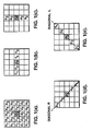
- FIG. 1(b) illustrates a (1 x 5) horizontal anti-median filter whose center element coincides with the center element c3 of the (5 x 5) MDP filter matrix.
- the filter array comprises a set of values c1 - c5.
- the imaging system will determine an intensity value for each individual element c1 - c5 and calculate a median (as described above) for this value.
- an absolute value of ⁇ 1 is determined as follows:
- FIGS. 1(d) and 1(e) show two diagonal one-dimensional (1 x 5) element anti-median sub-arrays, also centered at c3.
- FIG. 1(d) is a diagonal R (right) selected from the upper left downward to the lower right as shown, and includes the values a1, b2, c3, d4, e5.
- FIG. 1(e) is a diagonal L (left) array selected from the upper right downward to the lower left as shown, and includes the values a5, b4, c3, d2, e1.
- the diagonal L anti-median and the diagonal R anti-median filters are oriented at 45° and 135° respectively to the axis formed by the horizontal and vertical arrays. As above, the following quantities are calculated and stored.
- ⁇ 3 c3 - Med (Diagonal R),
- , ⁇ 4 c3 - Med (Diagonal L), and
- the MDP filter matrix is positioned during the scanning process at each location of the image such that each element of the matrix will be occupied with a data sample. In other words, the matrix does not extend beyond the boundaries of the image.
- the center of the matrix c3 is positioned or scanned to each pixel location of the image where this criterion is fulfilled.
- ) at each position is selected, and the corresponding value of the set ( ⁇ 1, ⁇ 2, ⁇ 3, ⁇ 4) is chosen as the output of the MDP filter for each scan location.
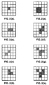
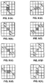
- FIGS. 2(a) - 2(h) show certain object shapes (represented by the shaded pixel areas) which a (5 x 5) MDP filter would preserve, independent of their respective orientations.
- object shapes represent images in the scene which do not subtend more than two (2) pixel elements in any one direction of any of the four anti-median filter arrays. It is noted that the shaded areas in these figures represent objects whose pixel intensities are detectably different from the white background intensities.
- the MDP filter of FIGS. 1 - 3 are formatted as (5 x 5) matrixes having four anti-median filters represented by different orientations of (1 x 5) arrays.
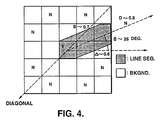
- certain outer ring elements specifically b1, d1, e2, e4, d5, b5, a4 and a2, are not used in the anti-median calculations. These elements have been designated “N" in FIG. 4. Because these elements are not included in the calculations, certain undesirable geometric forms are not eliminated or attenuated as much as desired.
- the object represented by the shaded area of FIG. 4 is one such example.
- the intensity of each pixel location in the array is reflected by its proportional shaded portion.
- a totally shaded cell has a value of one (1)
- a totally unshaded cell has a value of zero (0).
- the horizontal median value for the horizontal anti-median array (c1 - c5) is represented by element c5.
- the anti-median value (A) for the horizontal array is c3 minus c5 which is equal to 0.7, c3 being equal to 1 since it is entirely shaded and c5 being equal to 0.3, the percentage of cell area (c5) which is shaded.
- the median value for the diagonal L array is occupied by element b4, and the anti-median value (B) for this array is c3 minus b4 which is equal to 0.3. This object would partially survive as undesirable leakage in the embodiment described above.
- Undesirable leakage can be substantially reduced by including subtraction values (c3 - N) for each of the eight unused elements of the outer ring described above and represented by "N" in FIG. 4.
- the value of each one of these elements is subtracted from the center value c3 and absoluted as with each of the anti-median values for the horizontal, vertical and diagonal anti-median filters above.
- the resulting eight absolute values perhaps weighted by an arbitrary factor calculated to trade off relative performance in one area for performance in another, are included with the set of the four existing anti-median values to make up a new set having twelve values.
- the output of the MDP filter would then be the minimum of these twelve values.
- FIG. 1 the example of FIG.
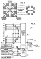
- FIG. 6 a representation of the second embodiment is shown.
- the white square elements represent the elements which are used in the first preferred embodiment of the horizontal, vertical and diagonal anti-median filters.
- the shaded elements are the ring elements for the second preferred embodiment as described above, each one possibly having a separate value.
- FIG. 7 discloses a system 10 showing a schematic implementation for developing an MDP filter output from the inputs of the anti-median filters and ring elements represented in FIG. 6.
- the first embodiment described above discloses an MDP filter with four anti-median sub-arrays. This description has been used merely as an example.
- the second preferred embodiment utilizes the pixels which are not included in the four anti-median sub-arrays of the first embodiment. These ring pixels, however, do not represent actual median values, and therefore do not produce the same kind of performance.
- the matrices of the preferred embodiments described above are symmetrical with respect to a center, i.e., square. It is entirely within the scope of the present invention to incorporate an MDP filter having any reasonable shape or size, as long as it comprises an odd number of pixel elements.
- FIG. 8 discloses eight additional anti-median sub-arrays which could have been included with the original four anti-median sub-arrays.
- FIG. 8(a) includes the (1 x 5) element array of (a2, b3, c3, d3, e4)
- FIG. 8(b) includes the (1 x 5) element array of (a2, b2, c3, d4, e4)
- FIG. 8(c) includes the (1 x 5) element array of (b1, b2, c3, d4, d5)
- FIG. 8(d) includes the (1 x 5) element array of (b1, c2, c3, c4, d5)
- FIG. 8(d) includes the (1 x 5) element array of (b1, c2, c3, c4, d5)
- FIG. 8(a) includes the (1 x 5) element array of (a2, b3, c3, d3, e4)
- FIG. 8(c) includes the (1 x 5) element array of (b1,
- each pixel includes the (1 x 5) element array of (d1, c2, c3, c4, b5);
- FIG. 8(f) includes the 1 x 5) element array of (d1, d2, c3, b4, b5);
- FIG. 8(g) includes the (1 x 5) element array of (e2, d2, c3, b4, a4);
- FIG. 8(h) includes the (1 x 5) element array of (e2, d3, c3, b3, a4).
- FIG. 9(b) shows an image derived from the original image of FIG. 9(a) by filtering with four cascaded anti-median filters.
- the cascaded anti-median filter arrangement is such that the anti-median values are calculated consecutively.
- the five element cascaded anti-median filters were arranged horizontally, vertically and diagonally at 45 and 135°, respectively.
- MDP filters can be employed in many applications where it is necessary to acquire and track unresolved objects embedded in severe background clutter. Although MDP filters are especially suited for background suppression applications, other potential uses will suggest themselves to those skilled in the art. For example, an MDP filter can be used to find line segments in a scene, such as may be associated with roads and rivers, and the orientation of these objects can be determined.
Landscapes
- Engineering & Computer Science (AREA)
- Physics & Mathematics (AREA)
- General Physics & Mathematics (AREA)
- Theoretical Computer Science (AREA)
- Computer Vision & Pattern Recognition (AREA)
- Multimedia (AREA)
- Image Processing (AREA)
Applications Claiming Priority (2)
| Application Number | Priority Date | Filing Date | Title |
|---|---|---|---|
| US67361891A | 1991-03-22 | 1991-03-22 | |
| US673618 | 1991-03-22 |
Publications (3)
| Publication Number | Publication Date |
|---|---|
| EP0504633A2 true EP0504633A2 (de) | 1992-09-23 |
| EP0504633A3 EP0504633A3 (en) | 1993-04-21 |
| EP0504633B1 EP0504633B1 (de) | 1998-04-29 |
Family
ID=24703403
Family Applications (1)
| Application Number | Title | Priority Date | Filing Date |
|---|---|---|---|
| EP92103276A Expired - Lifetime EP0504633B1 (de) | 1991-03-22 | 1992-02-26 | Minimaldifferenz-Prozessor |
Country Status (8)
| Country | Link |
|---|---|
| US (1) | US6111975A (de) |
| EP (1) | EP0504633B1 (de) |
| JP (1) | JPH0823888B2 (de) |
| CA (1) | CA2060407C (de) |
| DE (1) | DE69225264T2 (de) |
| IL (1) | IL101015A (de) |
| NO (1) | NO303555B1 (de) |
| TR (1) | TR26028A (de) |
Cited By (1)
| Publication number | Priority date | Publication date | Assignee | Title |
|---|---|---|---|---|
| EP0755023A1 (de) * | 1995-07-21 | 1997-01-22 | Laboratoires D'electronique Philips S.A.S. | Verfahren und Vorrichtung zur Raumfilterung von verrauschten numerischen Bildern |
Families Citing this family (17)
| Publication number | Priority date | Publication date | Assignee | Title |
|---|---|---|---|---|
| US6957350B1 (en) | 1996-01-30 | 2005-10-18 | Dolby Laboratories Licensing Corporation | Encrypted and watermarked temporal and resolution layering in advanced television |
| DE19849764B4 (de) * | 1998-10-28 | 2004-10-21 | Siemens Ag | Bildgebende Diagnostikeinrichtung |
| JP3625160B2 (ja) * | 1999-10-14 | 2005-03-02 | シャープ株式会社 | 画像処理装置 |
| US7266150B2 (en) | 2001-07-11 | 2007-09-04 | Dolby Laboratories, Inc. | Interpolation of video compression frames |
| US7177474B2 (en) * | 2003-11-10 | 2007-02-13 | Mobixell Networks Inc. | Video to animation conversion with file size constraint |
| EP1704510A4 (de) * | 2003-12-31 | 2009-09-09 | Lockheed Martin Missiles & Fir | Verfahren und system zur adaptiven zieldetektion |
| US20070200738A1 (en) * | 2005-10-12 | 2007-08-30 | Yuriy Reznik | Efficient multiplication-free computation for signal and data processing |
| US8595281B2 (en) | 2006-01-11 | 2013-11-26 | Qualcomm Incorporated | Transforms with common factors |
| US8849884B2 (en) | 2006-03-29 | 2014-09-30 | Qualcom Incorporate | Transform design with scaled and non-scaled interfaces |
| US8738678B2 (en) | 2009-10-29 | 2014-05-27 | Raytheon Company | Methods and systems for determining an enhanced rank order value of a data set |
| US8416986B2 (en) * | 2009-10-29 | 2013-04-09 | Raytheon Company | Methods and systems for processing data using non-linear slope compensation |
| JP2015121877A (ja) * | 2013-12-20 | 2015-07-02 | 東芝デジタルメディアエンジニアリング株式会社 | 中央値検索方法及び中央値検索装置 |
| KR102356230B1 (ko) * | 2017-08-14 | 2022-02-09 | 레이던 컴퍼니 | 종양의 검출을 위한 감산 알고리즘 |
| US11475558B2 (en) | 2019-11-13 | 2022-10-18 | Raytheon Company | Organ isolation in scan data |
| US11282209B2 (en) | 2020-01-10 | 2022-03-22 | Raytheon Company | System and method for generating contours |
| US11893745B2 (en) | 2020-12-09 | 2024-02-06 | Raytheon Company | System and method for generating and displaying contours |
| US11562512B2 (en) | 2020-12-09 | 2023-01-24 | Raytheon Company | System and method for generating and displaying contours |
Family Cites Families (10)
| Publication number | Priority date | Publication date | Assignee | Title |
|---|---|---|---|---|
| US4736439A (en) * | 1985-05-24 | 1988-04-05 | The United States Of America As Represented By The Secretary Of The Navy | Image preprocessing by modified median filter |
| US4703513A (en) * | 1985-12-31 | 1987-10-27 | The United States Of America As Represented By The Administrator Of The National Aeronautics And Space Administration | Neighborhood comparison operator |
| DE3751841T2 (de) * | 1986-03-17 | 1996-10-24 | Fuji Photo Film Co Ltd | Verfahren zur Glättung von Bildsignalen |
| JPH069061B2 (ja) * | 1986-03-26 | 1994-02-02 | 富士写真フイルム株式会社 | 画像デ−タの平滑化方法 |
| JPS63113776A (ja) * | 1986-10-31 | 1988-05-18 | Seiko Instr & Electronics Ltd | 画像の最大値,最小値変換回路 |
| US4783840A (en) * | 1987-12-04 | 1988-11-08 | Polaroid Corporation | Method for enhancing image data by noise reduction or sharpening |
| FR2638871B1 (fr) * | 1988-11-09 | 1994-06-03 | Jutand Francis | Procede et circuit de filtrage de signal de representation d'image |
| JPH03278057A (ja) * | 1990-02-14 | 1991-12-09 | Toshiba Corp | パターン検査装置 |
| US5020121A (en) * | 1990-08-16 | 1991-05-28 | Hewlett-Packard Company | Neighborhood block prediction bit compression |
| US5031227A (en) * | 1990-09-27 | 1991-07-09 | Loral Aerospace Corp. | Edge enhancement and smoothing in digital images |
-
1992
- 1992-01-30 CA CA002060407A patent/CA2060407C/en not_active Expired - Lifetime
- 1992-02-19 IL IL10101592A patent/IL101015A/en not_active IP Right Cessation
- 1992-02-26 DE DE69225264T patent/DE69225264T2/de not_active Expired - Lifetime
- 1992-02-26 EP EP92103276A patent/EP0504633B1/de not_active Expired - Lifetime
- 1992-03-05 NO NO920875A patent/NO303555B1/no not_active IP Right Cessation
- 1992-03-12 TR TR92/0300A patent/TR26028A/xx unknown
- 1992-03-18 JP JP4091564A patent/JPH0823888B2/ja not_active Expired - Fee Related
-
1996
- 1996-01-11 US US08/723,482 patent/US6111975A/en not_active Expired - Fee Related
Cited By (2)
| Publication number | Priority date | Publication date | Assignee | Title |
|---|---|---|---|---|
| EP0755023A1 (de) * | 1995-07-21 | 1997-01-22 | Laboratoires D'electronique Philips S.A.S. | Verfahren und Vorrichtung zur Raumfilterung von verrauschten numerischen Bildern |
| FR2737034A1 (fr) * | 1995-07-21 | 1997-01-24 | Philips Electronique Lab | Procede de traitement spatial d'une image numerique pour la reduction du bruit, et dispositif mettant en oeuvre ce procede |
Also Published As
| Publication number | Publication date |
|---|---|
| IL101015A (en) | 1996-06-18 |
| US6111975A (en) | 2000-08-29 |
| JPH05108820A (ja) | 1993-04-30 |
| TR26028A (tr) | 1993-11-01 |
| EP0504633A3 (en) | 1993-04-21 |
| CA2060407A1 (en) | 1992-09-23 |
| DE69225264D1 (de) | 1998-06-04 |
| NO920875L (no) | 1992-09-23 |
| DE69225264T2 (de) | 1998-08-20 |
| NO303555B1 (no) | 1998-07-27 |
| CA2060407C (en) | 1998-10-27 |
| NO920875D0 (no) | 1992-03-05 |
| EP0504633B1 (de) | 1998-04-29 |
| JPH0823888B2 (ja) | 1996-03-06 |
Similar Documents
| Publication | Publication Date | Title |
|---|---|---|
| EP0504633B1 (de) | Minimaldifferenz-Prozessor | |
| EP0135578B1 (de) | Auflösungserhöhung und zoom | |
| US6061100A (en) | Noise reduction for video signals | |
| CA2037066C (en) | Image processing technique | |
| EP0020417B1 (de) | Elektronische bildverdeutlichung | |
| Tom et al. | Morphology-based algorithm for point target detection in infrared backgrounds | |
| US5341439A (en) | System for texture-based automatic detection of man-made objects in representations of sensed natural environmental scenes | |
| US8582820B2 (en) | Coded aperture camera with adaptive image processing | |
| EP1093088A2 (de) | Auf Bereichsausweitung basiertes Geräuschverminderungsverfahren für digitale Bilder | |
| US6927804B2 (en) | Reducing color aliasing artifacts from color digital images | |
| Sauter et al. | Spatial filtering for speckle reduction, contrast enhancement, and texture analysis of GLORIA images | |
| He et al. | Bilateral edge detection on a virtual hexagonal structure | |
| Smith | Edge thinning used in the SUSAN edge detector | |
| AU662832B2 (en) | Real time connectivity algorithm system | |
| Gleed et al. | High-speed super-resolution techniques for passive millimeter-wave imaging systems | |
| US4910693A (en) | Method and apparatus for sampling lattice pattern generation and processing | |
| WO2001061993A1 (en) | Noise reduction for video signals | |
| Arivazhagan et al. | Performance comparison of discrete wavelet transform and dual tree discrete wavelet transform for automatic airborne target detection | |
| Hlavka | Simulation of LANDSAT multispectral scanner spatial resolution with airborne scanner data | |
| Rey et al. | A parametrized family of nonlinear image smoothing filters | |
| Qu | Directional morphological gradient edge detector | |
| Li | High-precision anti-jamming plant identification based on Faster-RCNN algorithm | |
| US20080187238A1 (en) | Noise Reduction Method based on Diamond-Shaped Window | |
| Tackett | Spatial domain image processing | |
| Amat et al. | Image Obtention and Preprocessing |
Legal Events
| Date | Code | Title | Description |
|---|---|---|---|
| PUAI | Public reference made under article 153(3) epc to a published international application that has entered the european phase |
Free format text: ORIGINAL CODE: 0009012 |
|
| AK | Designated contracting states |
Kind code of ref document: A2 Designated state(s): DE ES FR GB GR IT NL SE |
|
| PUAL | Search report despatched |
Free format text: ORIGINAL CODE: 0009013 |
|
| AK | Designated contracting states |
Kind code of ref document: A3 Designated state(s): DE ES FR GB GR IT NL SE |
|
| 17P | Request for examination filed |
Effective date: 19931020 |
|
| GRAG | Despatch of communication of intention to grant |
Free format text: ORIGINAL CODE: EPIDOS AGRA |
|
| 17Q | First examination report despatched |
Effective date: 19970619 |
|
| GRAG | Despatch of communication of intention to grant |
Free format text: ORIGINAL CODE: EPIDOS AGRA |
|
| GRAH | Despatch of communication of intention to grant a patent |
Free format text: ORIGINAL CODE: EPIDOS IGRA |
|
| GRAH | Despatch of communication of intention to grant a patent |
Free format text: ORIGINAL CODE: EPIDOS IGRA |
|
| GRAA | (expected) grant |
Free format text: ORIGINAL CODE: 0009210 |
|
| AK | Designated contracting states |
Kind code of ref document: B1 Designated state(s): DE ES FR GB GR IT NL SE |
|
| PG25 | Lapsed in a contracting state [announced via postgrant information from national office to epo] |
Ref country code: GR Free format text: LAPSE BECAUSE OF NON-PAYMENT OF DUE FEES Effective date: 19980429 Ref country code: ES Free format text: THE PATENT HAS BEEN ANNULLED BY A DECISION OF A NATIONAL AUTHORITY Effective date: 19980429 Ref country code: NL Free format text: LAPSE BECAUSE OF FAILURE TO SUBMIT A TRANSLATION OF THE DESCRIPTION OR TO PAY THE FEE WITHIN THE PRESCRIBED TIME-LIMIT Effective date: 19980429 |
|
| REF | Corresponds to: |
Ref document number: 69225264 Country of ref document: DE Date of ref document: 19980604 |
|
| ET | Fr: translation filed | ||
| ITF | It: translation for a ep patent filed | ||
| PG25 | Lapsed in a contracting state [announced via postgrant information from national office to epo] |
Ref country code: SE Free format text: LAPSE BECAUSE OF FAILURE TO SUBMIT A TRANSLATION OF THE DESCRIPTION OR TO PAY THE FEE WITHIN THE PRESCRIBED TIME-LIMIT Effective date: 19980729 |
|
| NLV1 | Nl: lapsed or annulled due to failure to fulfill the requirements of art. 29p and 29m of the patents act | ||
| PLBE | No opposition filed within time limit |
Free format text: ORIGINAL CODE: 0009261 |
|
| STAA | Information on the status of an ep patent application or granted ep patent |
Free format text: STATUS: NO OPPOSITION FILED WITHIN TIME LIMIT |
|
| REG | Reference to a national code |
Ref country code: GB Ref legal event code: 732E |
|
| 26N | No opposition filed | ||
| REG | Reference to a national code |
Ref country code: FR Ref legal event code: CA Ref country code: FR Ref legal event code: CD Ref country code: FR Ref legal event code: TP |
|
| REG | Reference to a national code |
Ref country code: GB Ref legal event code: IF02 |
|
| PGFP | Annual fee paid to national office [announced via postgrant information from national office to epo] |
Ref country code: DE Payment date: 20110223 Year of fee payment: 20 Ref country code: FR Payment date: 20110218 Year of fee payment: 20 Ref country code: IT Payment date: 20110217 Year of fee payment: 20 |
|
| PGFP | Annual fee paid to national office [announced via postgrant information from national office to epo] |
Ref country code: GB Payment date: 20110223 Year of fee payment: 20 |
|
| REG | Reference to a national code |
Ref country code: DE Ref legal event code: R071 Ref document number: 69225264 Country of ref document: DE |
|
| REG | Reference to a national code |
Ref country code: DE Ref legal event code: R071 Ref document number: 69225264 Country of ref document: DE |
|
| REG | Reference to a national code |
Ref country code: GB Ref legal event code: PE20 Expiry date: 20120225 |
|
| PG25 | Lapsed in a contracting state [announced via postgrant information from national office to epo] |
Ref country code: DE Free format text: LAPSE BECAUSE OF EXPIRATION OF PROTECTION Effective date: 20120227 |
|
| PG25 | Lapsed in a contracting state [announced via postgrant information from national office to epo] |
Ref country code: GB Free format text: LAPSE BECAUSE OF EXPIRATION OF PROTECTION Effective date: 20120225 |