EP0090113A2 - Continuous loading apparatus and method - Google Patents
Continuous loading apparatus and method Download PDFInfo
- Publication number
- EP0090113A2 EP0090113A2 EP82305865A EP82305865A EP0090113A2 EP 0090113 A2 EP0090113 A2 EP 0090113A2 EP 82305865 A EP82305865 A EP 82305865A EP 82305865 A EP82305865 A EP 82305865A EP 0090113 A2 EP0090113 A2 EP 0090113A2
- Authority
- EP
- European Patent Office
- Prior art keywords
- conveyor
- primary
- loading
- ram
- primary conveyor
- Prior art date
- Legal status (The legal status is an assumption and is not a legal conclusion. Google has not performed a legal analysis and makes no representation as to the accuracy of the status listed.)
- Granted
Links
Images


Classifications
-
- B—PERFORMING OPERATIONS; TRANSPORTING
- B65—CONVEYING; PACKING; STORING; HANDLING THIN OR FILAMENTARY MATERIAL
- B65G—TRANSPORT OR STORAGE DEVICES, e.g. CONVEYORS FOR LOADING OR TIPPING, SHOP CONVEYOR SYSTEMS OR PNEUMATIC TUBE CONVEYORS
- B65G65/00—Loading or unloading
- B65G65/02—Loading or unloading machines comprising essentially a conveyor for moving the loads associated with a device for picking-up the loads
- B65G65/04—Loading or unloading machines comprising essentially a conveyor for moving the loads associated with a device for picking-up the loads with pick-up shovels
-
- B—PERFORMING OPERATIONS; TRANSPORTING
- B65—CONVEYING; PACKING; STORING; HANDLING THIN OR FILAMENTARY MATERIAL
- B65G—TRANSPORT OR STORAGE DEVICES, e.g. CONVEYORS FOR LOADING OR TIPPING, SHOP CONVEYOR SYSTEMS OR PNEUMATIC TUBE CONVEYORS
- B65G65/00—Loading or unloading
- B65G65/02—Loading or unloading machines comprising essentially a conveyor for moving the loads associated with a device for picking-up the loads
- B65G65/14—Loading or unloading machines comprising essentially a conveyor for moving the loads associated with a device for picking-up the loads with jigging pick-up conveyors, e.g. duck-bills
Abstract
Description
- The invention relates to a loading apparatus and method particularly adapted for, but not limited to, use in a confined space, for example in underground excavation.
- In underground excavation, rock which has been fragmented by blasting is required to be removed from the working area. The rock or muck pile commonly has a steep angle of repose which is difficult to penetrate with loading apparatus during a mucking operation. If a loading apparatus requires a high tractive effort to penetrate the muck pile, slipping of the ground contacting means or mobile mounting means of the apparatus is common, resulting in rapid wear of the mobile mounting means and power train producing the tractive effort.
- Loading apparatus for mucking operations have been known for many years and some types include one or more conveyor assemblies having a gathering device at one end, for example a bucket, a back hoe or a scraper adapted to load material onto a fixed apron or hopper for feeding onto a forward or first conveyor. The gathering devices sometimes require a high degree of operator skill, and usually suffer from a high wear rate and low capacity. Also if the bucket or scraper of the gathering device is used on an articulated boom, additional headroom for the boom is required. After loading onto the conveyor, the material passes up the conveyor and then is fed either directly into a wheeled conveyance or onto a second conveyor remote from the loading apparatus for transport away from the work area. The apparatus is usually mounted for mobility on wheels or tracks, ie. the mobile mounting means and the apron of the primary conveyor is adapted to be advanced into the muck heap as the muck heap is depleted by the bucket or scraper. The apron of the conveyor assembly is forced into the muck heap by driving the apparatus forward, and this results in rapid wear of many components. Also excessive undulations or undesirable gradients of the ground supporting the apparatus, and resilience of tires or suspension often result in poor control of the scraper or apron, with consequent poor control of the gradient of the resulting road bed under the muck heap. The scraper or bucket of the gathering device usually loads the conveyor in a series of discrete feeding strokes interspersed with non-productive recovery strokes, and thus material is fed intermittently onto the apron reducing potential production.
- Attempts have been made to reduce the intermittent nature of the feeding of material onto the conveyor by use of auxiliary or feeder conveyors designed to feed material onto the first conveyor at a more constant rate than buckets, etc., or by use of vibrating or reciprocating fingers adjacent a leading portion or apron of the main conveyor to loosen material in the muck pile to facilitate entry of the apron or penetrating lip as the conveyor is advanced into the muck pile. Devices using a feeder conveyor for feeding material onto the main conveyor are shown in United States Patents #3,391,776 (Hancock) and #3,574,327 (Golfi), but in these devices, scrapers on a lower run of the forward or feeder conveyor merely push material onto the secondary conveyor and cannot easily penetrate a muck heap. The conveyors can move relative to each other but this is usually for positioning purposes and such devices are considered inappropriate for use in a mine due to the wide range of sizes of material in a mucking operation and limited head room in a mine. Devices having vibrating or reciprocating fingers adjacent a leading portion of the main conveyor to assist in penetration of the muck heap are shown in United States Patents #1,855,998 (Shannon) and #1,878,037 (Vodoz). While these latter devices may be adequate for handling some materials, it is felt that these devices have an excessive number of parts exposed to wear when disturbing the muck pile and would not be appropriate for material normally encountered in the harsh environment of mucking operations in hard rock excavation. Other loading devices having a vibrating trough or plate adjacent the leading portion of the conveyor have been used in coal mining in combination with vibrating or shaker conveyors. The plate is mounted directly on the conveyor to shake therewith, but such devices would be inappropriate in hard rock mining, and furthermore, are limited by very shallow angles of operation, thus requiring excessively long conveyors to attain a reasonable discharge height.
- The invention reduces difficulties and disadvantages of the prior art by providing a loading apparatus which enables a penetrating means at a forward end of a main or primary conveyor assembly to be fed essentially continuously into a muck heap for a relatively long working stroke, without the use of a complex and separate gathering device, thus reducing headroom requirements and associated maintenance problems. During the working stroke, material from the heap is distributed onto the conveyor in an essentially continuous manner as the conveyor is advanced into the muck heap, and the material conveyed in one working stroke is sufficient to load completely a stationary receiving conveyance located adjacent the rear end of the apparatus. Means are provided to permit relative movement between the primary conveyor and a supporting body of the apparatus so that during each working stroke, mobile mounting structure, such as tires, tracks, etc., carrying the body of the loading apparatus is stationary and thus the primary conveyor by itself is advanced into the muck heap in a controlled line of action or desired plane. Thus path or sweep of the penetrating means of the apparatus is relatively independent of the ground inclination or roughness, consequently producing a final road bed of desired inclination. Also, weight can be transferred from the mobile mounting means onto extendable legs, thus further improving control of the sweep by improving attitude control and augmenting--- resistance to mucking forces. Because the supporting body is stationary during penetration of the muck heap, use of the tractive power train is reduced with consequent reduction in transmission and tire or track wear. Prior to initiation of the working stroke, the supporting body is set in a desired attitude by adjusting the extendable legs independently, and once the body attitude is set, in some embodiments there is little requirement for a high degree of operator skill as other functions can be made to be semi-automatic. In some embodiments, particular modes of oscillation of the penetrating means are automatically selected by monitoring loading conditions. Portions of the apparatus that penetrate the muck heap and produce the oscillations can be made rugged and wear resistant so as to reduce maintenance problems and actuating structure associated therewith is protected from contact with the muck heap.
- As loading difficulty increases, the penetrating means is subjected to oscillation about a horizontal transverse axis to disturb the muck heap to facilitate loading of material onto the primary conveyor. The oscillation can be manually controlled reciprocation of the penetrating means at an amplitude and frequency determined by an operator. Alternatively, a semi-automatic oscillation can be initiated in which mucking conditions are sensed by the apparatus, and amplitude and frequency are automatically adjusted to search for optimum loading performance. In one alternative, the penetrating means can be raised to lighten mucking loads, and in another alternative the penetrating means can be subjected to two superimposed oscillations of widely differing frequencies and amplitudes.
- A loading apparatus according to the invention has a supporting body and primary and secondary conveyor assemblies having respective forward and rear conveyor portions. The two conveyor assemblies are disposed along a longitudinal axis so that the rear portion of the primary conveyor assembly is disposed above the forward portion of the secondary conveyor assembly. The apparatus is characterized by an extension means and a penetrating means which cooperate as follows. The extension means extends from the body and supports the primary conveyor assembly to permit essentially axial movement between the primary and secondary conveyor assemblies. The penetrating means is mounted adjacent the forward portion of the primary conveyor and is adapted to be oscillated as it penetrates material to facilitate loading of the material onto the primary conveyor.
- The apparatus can be operated in a manual mode which requires some degree of operator skill to select a frequency and amplitude of oscillation of the penetrating means. Alternatively in semi-automatic embodiments a sensor detects penetration or loading characteristics of material and an oscillating means is actuated which determines the frequency and amplitude of oscillation. Preferably as the resistance to penetration increases, the frequency of oscillation decreases and the amplitude increases, thus disturbing the material more effectively than merely forcing the penetrating means into the material.
- A detailed disclosure following, related to drawings, describes preferred embodiments of the invention which however are capable of expression in structure and method other than those particularly described and illustrated.
-
- Figure 1 is a simplified side elevation of an apparatus according to the invention shown in a retracted and lowered configuration,
- Figure 2 is a simplified top plan of the invention shown in the retracted configuration of Figure 1,
- Figure 3 is a simplified section on line 3-3 of Figure 1,
- Figure 4 is a simplified fragmented side elevation of a forward portion of the invention shown in an extended configuration,
- Figure 5 is a simplified fragmented detail section on line 5-5 of Figure 4
- Figure 6 is a simplified fragmented detail section on line 6-6 of Figure 4,
- Figure 7 is a simplified and sectioned side elevation at enlarged scale of a forward portion of a primary conveyor assembly and associated penetrating means,
- Figure 8 is a simplified fragmented side elevation of a forward portion of an alternative embodiment of oscillating means using a rotary actuator adjacent the primary conveyor,
- Figure 9 is a simplified fragmented section taken generally on line 9-9 of Figure 8,
- Figure 10 is a simplified fragmented side elevation of a forward portion of a second alternative embodiment of oscillating means using a hydraulic cylinder and rocker,
- Figure 11 is a simplified combination hydraulic/electrical schematic of a semi-automatic oscillating means according to the invention,
- Figure 12 is a simplified hydraulic/electrical schematic of an alternative semi-automatic oscillating means,
- Figures 13 -15 which appear on sheet 4 of the drawings, are simplified schematics, drawn in sequence, of modes of operation that are possible when operating the semi-automatic oscillating means of the Figure 12 embodiment,
- Figure 16 is a simplified diagram of a third embodiment of a semi-automatic oscillating means using hydraulic cylinders in series to produce a compound oscillation, and
- Figure 17 is a portion of a simplified hydraulic/electrical schematic used in conjunction with the embodiments of Figures 12 and 16.
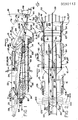
- A
loading apparatus 10 according to the invention has a supportingbody 12 carried on forward and rear pairs ofwheels longitudinal axis 19 of the vehicle at a constant angle to a datum, which steering is sometimes referred to as crab-like steering. The apparatus has an operator'sseat 17 provided with controls to control, amongst other things, anelectrical power unit 18 for use at an excavation face and areas where exhaust, heat or noise produces problems. Aseparate power unit 16, which is typically an internal combustion engine, is for use where exhaust, etc., are not problems. Alternatively the apparatus can be powered by one source of power. - The apparatus has primary and
secondary conveyor assemblies 21 and 22 respectively, the assembly 21 having forward andrear portions assembly 22 having forward andrear portions longitudinal axis 19 so that therear portion 25 of the primary conveyor assembly is disposed above theforward portion 27 of the secondary conveyor assembly to permit material to fall from the primary to the secondary conveyor assemblies. The primary conveyor assembly has aninclined chain conveyor 29 having fourchains 30 connecting a plurality of flights, some of which are shown in broken outline, theconveyor 29 being similar to those conveyors as commonly used in mucking operations. Thechain conveyor 29 has awidth 31 which is considerably wider thanwidth 32 of the secondary conveyor assembly, which has abelt conveyor 33 as commonly used in mines for transporting muck. Both conveyors pass through conveyor drive means so that upper surfaces of the conveyors move rearwardly in a general direction of anarrow 37. As seen in Figure 4, theforward portion 24 is inclined at anangle 35, about 15°, and therear portion 25 is inclined at ashallower angle 36, typically between 1° and 5°. Thus material moving up the primary conveyor is subjected to a rapid climb initially on the forward portion to reduce length of the conveyor, and is then transported essentially horizontally on the rear portion for discharge onto theforward portion 27 of the secondary conveyor assembly below, the discharged material being guided by an inclined taperingfunnel 34. - A penetrating means or
penetrator 38 has aforward tip 39 and is mounted adjacent theforward portion 24 of the primary conveyor assembly for swinging about atransverse penetrator axis 40 disposed horizontally and normally to thelongitudinal axis 19 in the top plan view of Figure 2. The penetrator axis is coincident with an axis of a forwardconveyor sprocket shaft 41 and permits the penetrating means to swing through an are 42 from a horizontal datum position as shown in full outline to a downwardlyinclined position 44 disposed to the horizontal at anangle 45, about 10°, through to an upwardlyinclined position 47 disposed to the horizontal at anangle 48, about 30". For some applications theangle 45 could be equal to theangle 48, ie. about 30°. A pair ofpenetrator moment arms penetrator actuating cylinders side members penetrator cylinders angles cylinders hydraulic cylinders moment arms cylinders - Thus, in summary, the penetrating means is hinged on the primary conveyor assembly for rotation about the horizontal
transverse penetrator axis 40 disposed normally to thelongitudinal axis 19. Also the oscillating means 57 include extensible and retractable hydraulic actuator means and coupling means extending between the primary conveyor assembly and the penetrating means so that actuation of the actuator means oscillates the penetrating means about the transverse axis. - The apparatus also includes a
ram member 58 extending rearwardly and axially from aprimary conveyor support 60, which supports a forward end of theportion 25 and a rear end of theportion 24 of the primary conveyor assembly. Thebody 12 has aram socket 62 which is complementary to the ram member and is adapted to receive the ram member therein. The socket is mounted on the body so as to be disposed generally axially, that is along thelongitudinal axis 19, and horizontally as viewed in the side elevation of Figure L As will be described with reference to Figure 5, the ram member and ram socket are generally rectangular in cross section and provide a sturdy support for ensuring axial movement of the ram member and primary conveyor assembly as will be described. As best seen in Figures 2 and 4, the ram member has forward andrear ends conveyor elevating cylinders 67 and 68 connected at theforward end 64, and aram actuating cylinder 69 connected at therear end 65. Theprimary conveyor support 60 also extends upwardly from theforward end 64 of the ram member to anupper hinge pin 76 to which is connected to theforward portion 24 of the primary conveyor to permit swinging thereabout relative to a conveyor hinge concentric with thepin 76. Thus thesupport 60 supports adjacent portions of the primary conveyor assembly at the conveyor hinge. The elevatingcylinders 67 and 68 extend to theside members forward portion 24 remote from thehinge pin 76 so that extension of the elevatingcylinders 67 and 68 swings theforward portion 24 about thepin 76 through anarc 78 to anuppermost position 79, shown in broken outline in Figure 1 only, in which theforward portion 24 is essentially horizontal. Thus theforward portion 24 is hinged to therear portion 25 to permit relative swinging therebetween about the hinge, and thecylinders 67 and 68 serve as elevating means which cooperate with theforward portion 24 and the ram member to swing theportion 24 relative to theportion 25 to vary height of thetransverse axis 40. When theforward portion 24 is in theuppermost position 79, and the penetrating means is fully elevated relative to theportion 24, thetip 39 of the penetrating means assumes anuppermost position 81 which is the highest portion of the apparatus. Theram actuating cylinder 69 has aninner end 83 secured adjacent a rear portion of thebody 12, and anouter end 84, ie. an end of the piston rod thereof, secured to therear end 65 of theram member 58 so that actuation of the ram actuating cylinder moves the ram member axially along the ram socket. Hydraulic apparatus and other telescoping means equivalent to the ram cylinder can be substituted. - As will be described with reference to Figure 6, the
rear portion 25 of the primary conveyor assembly has a pair ofparallel side members 85 and 86, each member having first guide means 87 extending along both sides of the conveyor. Thebody 12 has an upper support 88 having a second guide means 89 to engage the first guide means 87 of the primary conveyor assembly to permit essentially axial movement between theconveyor assemblies 21 and 22 and also to support therear portion 25 of the primary conveyor assembly above the secondary conveyor assembly. Thus, extension of theram member 58 produces concurrent forward movement of theforward portion 24 and therear portion 25 of the assembly 2L Thus it can be seen that the ram socket and second guide means, which are both fixed and carried on thebody 12, support theram member 58 andrear portion 25 of a movable excavating assembly 91 which includes the complete primary conveyor assembly 21, the penetratingmeans 38, theprimary conveyor support 60, thepenetrator cylinders cylinders 67 and 68 serving as elevating means, and theram member 58 serving as extension means. This total excavating assembly is movable "en masse", ie. all together as one connected assembly, relative to the body and this, permits the penetrating means 38 to be forced into a muck heap at a particular angle whilst thebody 12 and secondary conveyor assembly remain stationary. - Thus, in summary, the excavating assembly is supported on the extension means which extends forwardly from the body and supports the primary conveyor assembly to permit essentially axial movement between the primary and secondary conveyor assemblies. The extension means includes the ram means cooperating with the primary conveyor assembly and the body to permit longitudinal axial sliding movement of the primary conveyor relative to the body so that the penetrating means is forced into the material, the ram means concurrently supporting the forward portion of the primary conveyor.
- The
wheels body 12 and eliminate resilience effect of the tires and suspension by raising the body to relieve weight from the wheels during the mucking operation, and to provide forward movement for the penetrating means by extending the excavating assembly 91 as described. Such raising is accomplished by providing first andsecond pairs ram member 58, so as to accomodate terrain or other variables in the mine. In this way, when thebody 12 is set by the legs in a desired attitude, the ground under the muck heap can be scraped by the penetrating means 38 in a desired plane thus producing a final road bed of desired inclination. This reduces the irregularities in the final road bed that are commonly produced by prior art machines, some of which excavate whilst being supported on tires or tracks, where suspension resilience or irregularities in the existing road bed reduce control of a scraper or equivalent Clearly, in prior art machines where a scraper, etc. extends or overhangs considerably forwardly from wheels or tracks, any unevenness in the existing road bed is magnified at the scraper due to the overhang effect. Thus, weight is relieved, or completely eliminated from the mobile mounting means and reaction to thrust on the excavating assembly 91 is resisted by the four legs. In Figure 4, one leg of thefirst pair 93 is shown extended in broken outline and has a point to engage the ground to resist mucking forces. - A pair of similar laterally
extensible rams body 12 and have axes of extension andretraction acute angles extensible portions longitudinal axis 19 as best seen in Figure 2. An acute angle of contact with the side walls is preferred because the force from mucking is in direction of thearrow 37 and it can be seen that the acute angle of the rams contacting the walls resists slipping more effectively than if the rams were at right angles to the wall. Thus, the apparatus includes a first pair of extensible rams which are mounted on the body and, where appropriate, are adapted to extend generally laterally and horizontally from the body to engage adjacent oppositely facing surfaces to augment restraint of the apparatus against movement. - A pair of similar upwardly
extensible rams ram 108 is mounted on a knuckle joint 110 at a lower end thereof to permit swinging of the ram within a partially conical envelope III. so as to vary angle of contact of the ram with the surface with which it is engaged. A swing cylinder ll2 extends between thebody 12 and the ram to control angle of theram 108. When the first and second pairs oflegs rams body 12 is securely restrained within the mine opening. Thus, extension of the rams augments restraint of the apparatus against movement by increasing load on the means bearing weight of the apparatus, in this case, the first and second pairs oflegs - The
ram member 58 andram socket 62 are generally sy- metrical about theaxis 19, not shown, and thus one portion only will be described. Theram member 58 has a generally rectangular box section having four plate members, three only of which are shown, namely parallel upper andlower plate members vertical plate member 123 extending between themembers members member 123 and are provided with wear strips orrails ram guide roller 129 fitted between the wear strips. Theram socket 62 has upper andlower wall members side member 133 carrying an inwardly extendingspindle 134 which journals theroller 129 thereon, the spindle having alubrication passage 135 to lubricate theroller 129. Opposite sides of the ram member and ram socket are similar and it can be seen that the considerable loads existing between the ram member and ram socket are carried on the wear strips and respective rollers. At least four pairs of theram guide rollers 129 are fitted in the ram socket to support and guide the ram member as it extends and are also shown in broken outline in Figures 1, 2 and 4. The rollers and rails are defined as roller means to mount the ram for axial movement relative to the ram socket. - The primary conveyor assembly 21 and respective supports are generally symmetrical about the
axis 19, not shown, and thus one portion only will be described. Therear portion 25 of the assembly 21 has arear support spindle 141 extending non-rotatably between the side members and journalling thereon a rearconveyor sprocket shaft 143 carrying aconveyor sprocket 144. Thespindle 141 has an outer end adjacent theside member 85 journalling aconveyor guide roller 147 thereon. The support 88 of thebody 12 has a groovedside wall 152 having upper and lower wear surfaces orrails guide roller 147. Thus, the guide roller is restrained against vertical movement to resist forces imparted to the primary conveyor assembly during mucking, etc. , but is free to move axially as the conveyor assembly 21 extends. An opposite end of thespindle 141 is similar and thus it can be seen that theconveyor guide rollers 147 serve as the first guide means 87 for the rear portion of the primary conveyor assembly, and the grooved side walls and rails serve as the second guide means 89 of the body to engage the first guide means. The guide rollers and rails are defined as roller means associated with the first and second guide means to mount the primary conveyor assembly for movement relative to the supporting body. - The penetrating means 38 has upper and
lower plates concave wall 164 and side walls, not shown, so as to form a closed box-like assembly. Alower member 160 extending between theside members forward portion 24 terminate at an upwardlycurved lip 166 which, similarly to thewall 164, is concentric with thecommon penetrator axis 40 and axis of theconveyor sprocket shaft 41 of the primary conveyor. One of theconveyor chains 30, connected to the flights, not shown, for transporting material up the primary conveyor, passes around a sprocket, not shown, mounted on theconveyor shaft 41 which is hollow and encloses a fixedspindle 163 which journals theshaft 41 and the penetratingmeans 38. Anupper edge 165 of theconcave wall 164 is shown in a datum position designated 167 in which thelower plate 161 is horizontal, and theangles edge 165 is in an uppermost position, shown in broken outline 165.1, there is sufficient clearance to prevent interference with the chain. Likewise, in the lowermost position of the penetrating means, not shown, theupper edge 165 is no lower than thelip 166 of theundersurface 60. This is to direct muck relatively smoothly onto the conveyor and also to reduce ingress of muck between theframe 77 and thechain 30. - The
apparatus 10 moves into a position adjacent a muck heap and drives the penetrating means disposed in the datum position into the muck heap until resistance to penetration is such that the tires are close to the limit of adhesion. The apparatus is stopped and the first and second pairs oflegs extensible rams extensible rams ram actuating cylinder 69 is then extended so as to force the excavating assembly 91 forwardly from the position shown in Figure 1 towards the position shown in Figure 4. The penetrating means is set so as to be generally horizontal to aid penetration, but it can be inclined to accomodate the muck pile characteristics. Also the elevatingcylinders 67 and 68 are fully retracted initially so that the penetratingmeans 38 is at its lowermost position, but theforward portion 24 can be raised by extending thecylinders 67 and 68 if the muck heap is excessively high or resistant to penetration. - When the operator feels a particular crowding force is attained, or the rate of ram cylinder extension or loading of material becomes too slow, the
penetrator actuating cylinders axis 40 to thetip 39, a 20° total swing produces a maximum amplitude of swing of about 20 cms. In some conditions a 10° total swing at about 60 cycles per minute is effective. - The muck material immediately adjacent the penetrating means is disturbed by the oscillations, and material above the penetrating means falls onto the penetrating means and then onto the lower portion of the forward conveyor assembly, from where it is transported upwardly and rearwardly. The oscillations permit the tip of the penetrating means to penetrate into the muck heap in an essentially continuous manner, thus producing an essentially continuous stream of material falling onto the conveyor assembly, and essentially eliminating the intermittent feeding of mat- eral onto the conveyor assembly which is inherent in prior art apparatus using scrapers, buckets, etc. As the penetrating means moves into the muck pile, if the elevating cylinders remain inactive, the penetrating means follows a desired path which is dependent on inclination of the ram socket, and is independent of surface undulations and resilience of the suspension because the supporting
legs - In summary, the method of the invention is characterized by moving the primary conveyor assembly relative to the secondary conveyor assembly along the longitudinal axis so that the penetrating means penetrates material to be loaded without corresponding movement of the secondary conveyor assembly. The penetrating means is oscillated about a horizontal transverse axis disposed normally to the longitudinal axis to facilitate loading of material onto the conveyor.
- The penetrator oscillating means 57 of Figures 1 through 4 is relatively simple mechanically, but the
moment arms 51 and...52 andpenetrator cylinders rotary actuator 177 and coupling means for use with a suitable hydraulic circuit. - Referring to Figure 9, the
rotary actuator 177 is fitted adjacent one side of the primary conveyor assembly 21 and a rigidtubular coupling 179 connects to a second rotary actuator, not shown, fitted adjacent an opposite side of the conveyor so that both actuators are rigidly coupled and connected in such a way so as to rotate in similar directions simultan- eously. Theactuator 177 has a body secured bybrackets 178 to supporting structure of the primary conveyor assembly 21, not shown, and has anoutput shaft 180 connected to a swingingarm 182 which has a connectingpin 183 journalling ashoe 184 at an outer end thereof. An alternative penetrating means 186 is generally similar to the penetrating means 38 of Figures 1 through 4 and is journalled for swinging about apenetrator axis 188 adjacent a lower end of theforward portion 24 of the assembly 21. Anoperating arm 190 extends rearwardly and rigidly from a rear portion of the penetrating means 186 and is also rotatable about theaxis 188. Thearm 190 has an elongatedslot 192 adjacent an outer end thereof, the slot accepting theshoe 184 as a sliding fit therein for sliding between ends of the slot in a stroke having alength 194. Therotary actuator 177 can swing thearm 182 and thepin 183 through amaximum arc 196 of 180", and an axis 195 of the arm connecting theaxis 188 with an axis of thepin 183 oscillates within an envelope defined bybroken lines rotary actuator 177 and the penetrating means. Therotary actuator 177 is a hydraulic actuating means and has a first portion cooperating with the primary conveyor assembly and a second portion cooperating with the coupling means. - By geometry, in operation it can be seen that as the rotary actuator swings the
arm 182 through thearc 186, thepin 183 andshoe 184 cooperate with theoperating arm 190 to swing the axis 195 of thearm 190 from a datum 202, which is shown coincident with the axis 195 in Figure 8, through alower angle 203 and anupper angle 204 and back again. This reciprocating of thearm 190 results in an equal but opposite oscillation of the alternative penetrating means 186 through equivalent upper and lower angles equal to theangles angles arm 190, and a similar arm, not shown, at an opposite side of the penetrating means, oscillate through an angle of about 40° and thus can be easily accomodated in a low profile protective enclosure orside casing 206 which protects the hydraulic components and does not increase excessively size of the penetrating means. Thus, the oscillating means 175 is less vulnerable to damage when compared with the oscillating means 57 of Figures I through 7. The actuator is supplied with a hydraulic fluid flow which alternates in direction as previously described so as to oscillate the rotary actuator. - A third embodiment of a penetrator oscillating means 2ll has similar advantages to the second embodiment of Figures 8 and 9, but eliminates the cost and complications of the rotary actuators. One side only of the penetrating means is shown, the structure being symmetrical about the
axis 19 of Figure 2. An alternative penetrating means 214 is journalled for rotation about apenetrator axis 215, the penetrating means having a relativelyshort moment arm 217 extending from each side of the conveyor, one only being shown, and fitted withinprotective side casings 218 of the forward portion of the primary conveyor assembly. Arocker arm 220 is journalled for swinging about arocker axis 221 relative to the casing, and a connectinglink 223 extends between and is hinged to a lower end of therocker arm 220 and to an outer end of themoment arm 217. Apenetrator actuating cylinder 226 has afirst portion 227 mounted on the casing with a second portion, ie. apiston rod 228, connected to an upper end of therocker arm 220. It can be seen that reciprocation of thecylinder 226 oscillates the rocker arm about therocker axis 221, which movement is transmitted through the connectinglink 223 andmoment arm 217 to the penetrator means which swings through upper andlower angles datum 230. It can be seen that the rocker arm, connecting link, moment arm and associated structure serve as coupling means 233 and provide a low profile penetrator oscillating means producing a similar range of movement to the previously described penetrating means without the complexity of the rotary actuators of Figures 8 and 9. Similarly to the penetrator oscillating means of Figures I through 7, and of Figures 8 and 9, a flow control means such as a manually controlled directional valve and associated circuitry, or that shown in Figures ll and 12, cooperates with the cylinder to produce reversal of flow in conduits so as to result in oscillation of the penetrating means. As in the previous oscillating means embodiments, the oscillating means cooperates with the penetrating means to oscillate the penetrating means about the transverse penetrator axis. - The operation of the embodiments of the invention disclosed in Figures 1 through 10 have been described for use with the simple manual hydraulic circuit, wherein movement of the penetrating means is controlled by manually operable valves which control fluid flow to the requisite hydraulic apparatus, following conventional practice. Whilst such an arrangement might be preferred in some circumstances, for other applications a semi-automatic operation is preferable wherein the penetrating means is oscillated in an amount dependent on the characteristics of the muck pile. In general, the alternative hydraulic and electrical circuits which are to be described with reference to Figures 11 and 12, which includes the auxiliary circuit of Figure 17, incorporate sensing means which are responsive to the speed of advance of the penetrating means into the muck pile, or the force required to penetrate the muck pile, that is the sensor means are responsive to characteristics of material acting on the penetrating means or rate of loading. The sensing means is coupled to an oscillating means which oscillates the penetrating means about its transverse axis when required which assists considerably in penetrating a muck pile, and reduces skill demands on the operator. The semi-automatic systems allow penetration of the penetrating means into the muck pile without oscillation, so long as penetration is maintained above a pre-determined speed, or the force required to maintain penetration is below a pre-determined value. Thus, for penetration into a relatively free flowing muck heap, the oscillating feature might be mostly inactive and this reduces wear on the actuating mechanism. When penetration into the muck heap falls below the pre-determined speed, or force increases above the pre-determined value, the sensing means activates the oscillating means which commences the oscillation, which would thus assist in penetration of a less free flowing muck heap. Manual override of the oscillating means is also envisaged. In Figures 11, 12 and 17, normal hydraulic lines are shown in full, hydraulic pilot lines are shown in small broken lines, and electrical connections are shown as larger broken lines.
- The two penetrating
cylinders ram actuating cylinder 69 are integrated hydraulically and electrically into a powering and sensing circuit, generally 240. The circuit includes ahydraulic pump 242 which is coupled hydraulically to two four-way, three-positiondirectional valves cylinders directional valve 247 is also coupled to the pump and controls flow relative to theram cylinder 69. A normally-closed, pilot-operatedvalve 243 controls return flow of fluid relative to the pair ofcylinders valves check valves pressure regulating valve 259. Thedirectional valve 247 controls flow relative to arelief valve 261, which is disposed in parallel with an adjustable orifice andcheck valve assembly 262 which controls flow through acheck valve 264 connected to a normally-closedsolenoid valve 266. Electrical pressure switches 268 (normally open) and 269 (normally closed) are in series with each other and are electrically connected to the switch 252, and also to thevalve 266 which controls flow to a variable speed hydraulic motor 27L Themotor 271 is mechanically connected tocams valve 245. The pressure switches 268 and 269 are responsive to fluid pressure in pilot lines connected to opposite ends of theram cylinder 69, termedram cylinder circuit 270, as will be described. - In operation, the apparatus approaches the muck heap with the
ram cylinder 69 retracted until the penetratingmeans 38 is closely adjacent the muck heap. Thebutton 251 of the automatic "on" switch 252 is depressed and held down to energize thedirectional valve 247 and theram cylinder 69 extends to move the penetrating means further into the muck heap. The solenoid valve 253 is also de-energized and fluid pressure, which is controlled by thepressure regulating valve 259, is admitted into thecylinders valve 243 is opened to vent the downstream side of thecylinders pressure switch 268 is initially de-energized and, as resistance to penetration of the penetrating means into the muck heap increases, pressure rises in theram cylinder 69 until, at a pre-determined pressure, theswitch 268 closes as the pilot pressure exceeds a pre-determined value. The closing of theswitch 268 energizes thepressure switch 269, which is at that time held open by pilot pressure as follows. As theram cylinder 69 extends, the return fluid displaced by the piston from a chamber of thecylinder 69 into thereturn circuit 270 is pressurized byrelief valve 261 and theorifice assembly 262. As long as the ram cylinder extends at a sufficiently high rate, therelief valve 261 is maintained open and return fluid in thecircuit 270 is at a relief pressure which maintains the pilot pressure sufficiently high to hold thepressure switch 269 open. - As the rate of extension of the
ram cylinder 69 decreases, fluid pressure in thereturn circuit 270 drops, and when this pressure decreases below a pre-determined pressure, the pilot pressure can no longer hold thepressure switch 269 open, and so theswitch 269 closes, which energizes thesolenoid valve 266 which controls the hydraulic motor 27L Themotor 271 starts to rotate, with a corresponding rotation of thecams directional valve 245 is alternately reversed, ie. thevalve 245 is subjected to oscillating or alternating signals. Theoscillating valve 245 in turn alternately reverses fluid flow to thecylinders - It can be seen that the frequency of oscillation of the penetrating means is in proportion to rate of extension or advance of the
ram cylinder 69. At a higher rate of ram advance, a relatively large volume of return fluid in thecircuit 270 rotates thehydraulic motor 271 at a relatively high speed, which consequently rotates thecams circuit 270 also decreases with a consequent reduction of motor r.p.m., cam r.p.m. and frequency of oscillation of the penetrating means. Because the volume of fluid flowing into thecylinders directional valve 245 decreases, a correspondingly greater volume of fluid flows into thecylinders cylinders valve 245 decreases, which results in a greater amplitude of swing of the penetrating means. Thus, as frequency of oscillation of themeans 38 decreases, amplitude of oscillation increases. This is a desirable relationship because, as the resistance to penetration increases, the corresponding decrease in oscillation frequency and increase in amplitude reduces considerably the force required for penetration into the muck heap. For most materials encountered, as the muck heap resists penetration, mostly due to firmly embodied rocks or larger rocks, oscillating the penetrating means through a greater angle causes greater disturbance with corresponding less ram force required for penetration. Typical automatic frequencies of oscillation range from about 10 cycles per minute to about 200 cycles per minute, depending on the amplitude which can vary from an approximate 5° range up and down from the datum at the higher frequencies, to the wider range of 10° down and 30° up for the lower frequencies. In some conditions, the extreme range of 30° down to 30° up is preferable, and this would occur at a low frequency. The relationship between extension of the ram and oscillation frequency of the penetrating means can be varied by changing the volume displacement in thehydraulic motor 271 and by adjusting restriction of theorifice 262. - A further development of the hydraulic control system of Figure ll is shown in Figure 12 and provides automatic raising of the
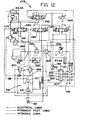
conveyor elevating cylinders 67 and 68 in response to hydraulic fluid pressure in the ram circuit. In this second alternative embodiment, theforward portion 24 of the primary conveyor assembly is raised incrementally to an elevation which allows easier penetration of the penetrating means into the muck pile. The Figure 12 circuit also provides automatic reversal of the ram stroke while encountering a pre-determined resistance to penetration, or an equivalent slow rate of advance or extension of the ram. - A second alternative
hydraulic circuit 278 is powered by a hydraulic pump 280 which supplies fluid to four four-way, three-position directional valves designated 282 through 285, which are incorporated in a circuit containing the penetrating meanscylinders ram cylinder 69 and theconveyor elevating cylinders 67 and 68. A normally-closed, pilot-operatedvalve 279 controls return flow of fluid relative to thecylinders multiple pole switch 281 controls electrical supply to thevalve 282 and other electrically actuated components as will be described. Thevalves actuating cylinders valve 284 controls fluid flow relative to theram actuating cylinder 69, and thevalve 285 controls fluid flow relative to the elevatingcylinders 67 and 68. A normallyopen solenoid valve 288 controls fluid flow from thevalve 284, which flow is pressure regulated and controlled by apressure reducing valve 290 and a check valve 29L Pressure in conduits connecting the rear of theram cylinder 69, termedram cylinder circuit 293, is controlled by arelief valve 295, which is in parallel to a variable orifice andcheck valve assembly 297. Lines connect thecircuit 293 of one end of the ram cylinder with a normally closedpressure switch 299, which switch is electrically connected to a normallyopen pressure switch 301, which is responsive to pilot pressure at an opposite end of the cylinder. - A normally-open pressure switch 305 is electrically connected to the
valve 285 and a multiplecontact limit switch 307 which is mechanically actuated byactuators cylinders 67 and 68. Apressure relief valve 309 has a pressure relief setting which is controllable by pilot pressure in a pilot line extending from a hydraulically actuated rheostat 3ll which is shown in a low resistance position. Acheck valve 313 closes a line from thevalve 285. The rheostat 3ll is electrically connected to a variable speedelectrical motor 315 to control speed of the motor, which is mechanically connected tocams valve 283 controlling thepenetrator cylinders limit switch 307 has four pairs of contacts designated 321, 322, 323 and 324 which are connected electrically to components as will be described. - In operation, the
system 278 functions similarly to the system 2.40 of Figure U with the exception that automatic reversal of the ram stroke and automatic raising of the forward portion of the primary conveyor assembly are provided as will be apparent from the following description. Initially the automatic "on"button 281 is depressed and held so as to energize theram operating valve 284 which moves into the ram forward advance position to cause the penetrating means to advance forwardly into the muck heap. Simultaneously, fluid is directed through thecheck valve 291 topressure reducing valve 290 which is set at a pre-determined pressure. Reduced fluid pressure from thevalve 290 flows through thesolenoid valve 288 into rear chambers of thecylinders cylinders valve 279 to sump. As the penetrating means penetrates further into the muck pile, resistance to penetration increases which consequently causes fluid pressure to increase, causing the normallyopen switch 301 to close. As long as theram cylinder 69 extends, fluid that is exhausted by the piston from the chamber of thecylinder 69 is maintained at a pressure byrelief valve 295 andvariable orifice assembly 297. Thus, pressure in thecircuit 293, which is termed ram advance control pressure, is sufficiently high to maintain theswitch 299 open, but as the rate of extension of the ram decreases, the ram advance control pressure similarly decreases and theswitch 299 finally closes at a pre-determined pressure which reflects a particular rate of ram extension, ie. speed of ram extending from the cylinder. When thepressure switch 299 closes, thevalve 288 also closes, and thecams circuit 293 orients the rheostat into the low resistance position against the spring force as shown. Theelectric motor 315 is thus driven at maximum speed, simultaneously rotating the cams of the switch means 319 at maximum speed which alternately energize thecontrol valve 283 between alternate positions at maximum frequency. Thevalve 283 controls flow direction to thecylinders cylinders cylinders - As the rate of extension of the ram cylinder further decreases, spring force of the rheostat 3ll overcomes the decreasing control pressure in the
circuit 293 which causes the rheostat to increase resistance, which results in a corresponding reduction in r.p.m. of themotor 315. Thus, r.p.m. of thecams cylinders circuit 293 is reflected as a minimum pressure on thevalve 309 which determines force on rear faces of the portions of the elevatingcylinders 67 and 68. Thus, when the penetratingmeans 38 is forced downwardly a reaction force on the cylinders overcomes the force due to the decreasing pressure on the rear faces of the pistons in theconveyor elevating cylinders 67 and 68. That is, there is now an inbalance in forces on opposite sides of the pistons of thecylinders 67 and 68, which causes the rams of thecylinders 67 and 68 to extend and to raise the forward portion of the conveyor. The forward portion of the conveyor will continue to rise until there is less resistance to penetration of the penetrating means, which results in a corresponding increase in rate of extension of thecylinder 69. As the ram extension speed increases, pressure in thecircuit 293 increases which results in a corresponding feedback signal to decrease resistance of the rheostat 3ll with a corresponding increase in oscillation frequency. Thus, the hydraulic circuit "searches" for an optimum loading rate commensurate with loading conditions as the forward portion of the conveyor is raised to a pre-determined height, depending on height and type of muck pile. Two relatively extreme types of loading conditions produce two different modes of operations as will be described with reference to Figures 14 and 15. In this embodiment, it can be seen that a portion of the circuit also serves as a sensor means to control the elevating of the conveyor assembly which is actuated when a particular operating condition is attained. In effect, the sensor senses a decrease in rate of loading or ram advance such that the ram advance drops below a pre-determined minimum rate, and then automatically allows theforward portion 24 to rise so that the penetrating means is advanced into the material at a higher elevation. - When the forward portion of the conveyor reaches an upper limit of elevation, the
actuator 310, cooperating with thecylinders 67 and 68, now actuates thelimit switch 307. which produces a change in the operation as follows. At first thecontacts 322 are opened and thevalve 284 controlling the ram cylinder is closed. This stops extension of the ram andpressure switch 301 now opens and stops oscillation of the penetrating means and thevalve 288 is energized. Next thecontact 321 closes which energizes thevalves 284, which reverses flow to the ram cylinder, causing the ram cylinder to retract. Thecontact 324 now closes, which energizes thevalve 282 which raises the tip of the penetrating means to a maximum raised position. Next thecontact 323 closes which energizes the switch 305 and theram cylinder 69 now retracts until it reaches the end of its stroke, with a consequent increase in pressure in thecircuit 293 closing the switch 305. This energizes thevalve 285, which lowers theforward portion 24 of the conveyor to the original lowered position, and at this point, theactuator 308 cooperating with thecylinders 67 and 68 de-activates thelimit switch 307, thus re-opening all thecontacts contact 322. At this point, the system returns to the penetrating means advance mode, ie. extension of theram cylinder 69 as previously described, and the cycle above is repeated until theram cylinder 69 reaches the end of its forward travel, that is at the end of its stroke. At this stage, the ram would normally be retracted manually, and the whole apparatus would be advanced further towards the muck heap to recommence the operation. - The
cams - Alternatively, other means of controlling the oscillating frequency in relation to ram cylinder advance can be used. For-example, the
variable orifice valve 297, the rheostat 3ll andmotor 315 can be replaced by a variable spaced hydraulic motor driven by the return fluid from theram cylinder 69 in a manner similar to that of the previously described embodiment. The speed of the cams mounted directly on the hydraulic motor shaft would be in direct proportion to ram cylinder advance speed, and proportionality between the oscillation frequency and ram advance can be changed by changing the displacement of the motor. Automatic sequencing and sensing can be attained as above using electronic means or by fluid logic or by other hydraulic means. - A further alternative control system can be substituted if desirable for muck which is more difficult to load, and this embodies a further alternative sensing means similar to that previously described, but one that not only controls oscillation of the penetrating means, but also controls cyclical extension of the
ram cylinder 69. Theram 69 can similarly be oscillated in a phase difference relative to oscillation of the penetrating means so that thetip 39 of the penetrating means follows a circular orbit or locus, or any closed locus. The locus of thetip 39 can be varied to provide the best loading action for the characteristics of the material to be loaded by adjusting the direction and rate of flow of the hydraulic fluid into the appropriate hydraulic cylinders. It can be seen from the above description of the two circuits that the circuit of Figure 12 could be more easily adapted for this latter arrangement, but this adaptation is not described in detail. - Thus, when considering the circuits of Figures II and 12, the ram cylinder is thus a hydraulic apparatus which has the associated ram hydraulic circuit receiving and discharging fluid having hydraulic parameters related to fluid pressure and fluid flow rate. Also the pressure
responsive switches motor 271 of Figure U, or themotor 315 of Figure 12, connected to means controlling fluid flow to the oscillator means. It can be seen that the sensor means of either circuit includes a pressure responsive electrical switch communicating with one chamber of the ram cylinder, in each case herein disclosed with the conduit receiving fluid discharged from the chambers by the piston, but this is not essential to use that particular conduit. The fluid parameters reflect rate of extension of the ram, which is also a reflection of rate of loading of material on the conveyor. A more direct means of measuring rate of loading would be monitoring input of power for driving the conveyor itself. Also with suitable changes the ram actuating cylinder could be retracted during forward movement of the primary conveyor, and thus the sensor means could be responsive to ram retraction. The oscillator means includes alternating electrical switch means and motor means to drive the switch means, the motor means being responsive to the pressure responsive electrical switch. The oscillator means also includes an electrically actuated directional valve connected to the reversing electrical switch means and controlling flow relative to hydraulic actuator means cooperating with the penetrating means. In both circuits, the switch means are a pair of rotary cam actuated alternating switches phased relative to each other so that the directional valve controlled by the switch means alternates flow to the hydraulic actuator means of the penetrating means at a frequency responsive to the rotation of the cams. Also, the motor has a rotary output coupled to the alternating switches and is rotated in an amount proportional to flow of fluid in the ram circuit. In summary, the sensor means cooperates with the oscillator means to vary frequency of oscillation of the penetrating means. - In summary, the semi-automatic method associated with the circuits of Figures 11 and 12 is characterized by sensing characteristics of the material to be loaded by monitoring a rate of loading, and varying automatically amplitude and frequency of oscillation of the penetrating means. This is attained by sensing a decrease in rate of loading of material, or alternatively a decrease in rate of advance of the penetrating means into the material due to resistance to penetration, and automatically decreasing the frequency and increasing the amplitude of oscillation of the penetrating means. Thus the characteristics of the material and rate of loading of material are sensed by automatically monitoring rate of advance of the penetrating means into the material.
- The descriptions following relate to modes of operation of the loading apparatus using the semi-automatic circuit of Figure 12, which subjects the penetrating means to an operating elevation and an oscillation dependent on loading conditions.
- Referring to Figure 13, the
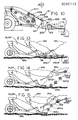
forward portion 24 of the primary conveyor assembly 21 is shown in full outline in an initial starting position with the penetrating means 38 shown positioned above an existingroad bed 330 and about to penetrate amuck pile 331 having very easy loading characteristics with a shallow angle of repose, shown in broken outline. As the ram means, not shown, extends theportion 24 to a maximum forward position, shown in broken outline at 24.1, when a pre-determined resistance is felt, the penetrating means is oscillated at a normal frequency and amplitude. Three sequentially advancing positions of a forward portion of the penetrating means are shown in broken outline positions 332.1 through 332.3, the broken outline positions defining alocus 333 which is generally parallel to theroad bed 330. This represents easy mucking conditions wherein the oscillating means is actuated minimally as needed and this disturbs the muck pile sufficiently to enable the muck to fall easily onto the forward portion of theconveyor 24 without raising the forward portion. - Referring to Figure 14, a
muck pile 335 having relatively easy loading characteristics is shown having a steeper angle of repose and the penetratingmeans 38 is shown in four sequentially advancing positions designated 337.1 through 337.4, so as to define alocus 339, shown in broken outline. It can be seen that thelocus 339 is rearwardly concave and this represents a typical path of the penetrating means through a muck pile of relatively easy loading characteristics. Thus, in such a muck pile, the method using the semi-automatic system as described with reference to Figure 12, is characterized by raising the forward portion of the primary conveyor assembly and simultaneously advancing the penetrating means so that the penetrating means describes a locus of a rearwardly concave shape. - Referring to Figure 15, the apparatus is shown penetrating a
muck pile 342 of relatively difficult loading characteristics and having a very steep angle of repose. The penetrating means is shown in four sequential positions 344.1 through 344.4 so as to define alocus 346 of rearwardly convex shape. Thus, when loading a muck pile of relatively difficult loading characteristics, the forward portion of the primary conveyor is raised and the penetrating means is advanced simultaneously so that the penetrating means describes a locus of rearwardly convex shape. - It can be seen above that oscillating the penetrating means in combination with ram advance and simultaneously raising of the forward portion of the conveyor, when required, describes a locus dependent on characteristics of the muck pile, which reflects rate of loading, and programming of the hydraulic parameters of the circuit. Clearly, a wide range of operating functions can be accomodated by selecting circuit parameters such that the locus of the penetrating means can be disposed between an essentially straight horizontal line as shown in Figure 13, to a reawardly convex or concave shape as shown in Figures 14 and 15.
- A fourth embodiment 351 of an oscillating means is for use in muck piles of particularly difficult loading characteristics and differs from the previously described oscillating means by providing apparatus and method which superimposes one type of oscillation upon another type of oscillation of the penetrating means so as to provide a compound oscillation of two distinct oscillations, ie. a least two modes of oscillation. Referring to Figure 16, the penetrating
means 38 is shown hinged for oscillation about thepenetrator axis 40 adjacent theforward portion 24 of the primary conveyor assembly 2L Thepenetrator moment arm 51 extends from theaxis 40, but thepenetrator cylinder 54 of Figure 1 is eliminated and a separatecompound oscillation apparatus 353 is substituted. Theapparatus 353 includes a large strokehydraulic cylinder 355 having a first portion orbody 356 hinged to theforward portion 24, and a second portion orpiston rod 358 extending therefrom. Therod 358 carries asmall stroke cylinder 360 aligned therewith and having a respectiveshort piston rod 362 connected to an outer end of the moment arm 5L It can be seen that thecompound oscillating apparatus 353 includes large and small stroke hydraulic actuators or cylinders arranged in series with each other and extending between the primary conveyor assembly and thearm 51 to provide coupling means equivalent to those as previously defined and described. - Referring to Figure 17, an
auxiliary circuit 364 is coupled to thecircuit 278 of Figure 12, and is used to actuate thesmall stroke cylinder 360 of Figure 16. The large andsmall stroke cylinders large cylinder 355 being controlled by thedirectional flow valve 283 of Figure 12 which controls fluid flow relative to thecylinder 355 throughconduits cylinders directional valve 367 cooperates withconduits small stroke cylinder 360. Avariable displacement pump 372 feeds hydraulic fluid to the circuit through acheck valve 368, and anaccumulator 375 andvariable relief valve 376 controls fluid flow characteristics. Anelectrical motor 378 is coupled directly to twocams valve 367 so as to reciprocate thevalve 367 to reverse fluid flow relative to thecylinder 360. An "on"switch 382 can be closed automatically or manually so as to supply electrical power to theauxiliary circuit 364 so as to actuate thesmall stroke cylinder 360 as required. When theswitch 382 is open, thecircuit 364 is inactive, and thevalve 367 locks theconduits large stroke cylinder 355 functions equivalently to thepenetrator actuating cylinders - In operation, in normal loading conditions, the
circuit 364 is inactive and the penetrating means penetrates the muck pile, not shown, to swing, if necessary, through an are of maximum amplitude shown as thearc 42, of Figure I, representing the range of movement of twoarcs auxiliary circuit 364 can be actuated manually or by suitable sensing means, not shown, to close theswitch 382 so that thedirectional valve 367 alternately supplies fluid to opposite ends of thesmall stroke cylinder 360. This causes the small stroke cylinder to produce a small amplitude, relatively high frequency oscillation of the penetrating means, and undesignated upper and lower positions of the penetrating means are shown in broken outline for each of the three main positions of the penetrating means. A maximum linear amplitude of oscillation due to thecylinder 360 is shown in Figure 16 for each position and designated 384. The frequency and amplitude of oscillation due to the small stroke cylinder is dependent on speed of rotation of thecams pump 372 and relative displacement of thecylinder 360. In general, the frequency of oscillation of the small stroke cylinder would be relatively high when compared with thelarge stroke cylinder 355, and clearly, due its shorter stroke, will be of smaller amplitude when compared with the maximum amplitude of the large stroke cylinder. For thesmall cylinder 360, a frequency range of between about 100 cycles per minute and 200 cycles per minute, and amplitude of about 5 ems. maximum total swing at thetip 39 is considered suitable for many mucking conditions. - It is envisaged that, for many mucking conditions, only the
small stroke cylinder 360 will be oscillated as this requires less power and, being capable of a higher frequency, may be more effective in disturbing muck piles of relatively small rocks. However, for the muck piles of large and heavy rocks, it is expected that the amplitude range and frequency of thelarge stroke cylinder 355 will be more effective than thecylinder 360 for disturbing the muck pile. For convenience, the oscillation of the penetrating means that occurs when the auxiliary circuit is also operated can be considered as a compound oscillation having primary and secondary oscillations compounded to produce a compound oscillation. Each oscillation is independently variable so as to have a frequency and an amplitude which can vary from zero to a desired value. The primary oscillation from thecylinder 360 or first hydraulic means would have a relatively high frequency and low amplitude, and, at the higher frequencies, thecylinder 360 may not complete its full stroke and thus amplitude of the primary oscillation could vary from zero to a relatively low maximum. The secondary oscillation from thecylinder 355 or second hydraulic means would have a frequency which varies from zero to a relatively low maximum, eg. 80 cycles per minute, and an amplitude which varies from zero to a relatively high maximum, eg. 40 cms. Typical primary oscillations might be 200 cycles per minute for a 5 cm. total amplitude, and a typical secondary oscillation might be 80 cycles per minute with a 30° or 20 cm. total amplitude, or 40 cycles per minute with a 40° or 40 cm. total amplitude. The oscillation means thus includes a compound oscillation apparatus adapted to apply oscillations as above described, and includes a small and large stroke actuator cooperating with the penetrating means so that the small stroke actuator applies the primary oscillation and the large stroke actuator applies the secondary oscillation. - Clearly, alternative hydraulic and electrical circuits can be devised in which a large stroke cylinder can be subjected to two compound fluid flows to produce a compound frequency on one cylinder, thus eliminating the short stroke cylinder in series with the large stroke cylinder. Whilst this would produce a more complex hydraulic circuit, there would be some structural simplification and clearly, the short cylinder would be eliminated. Also, such an arrangement could be utilized with the alternative hydraulic oscillating means of Figures 8, 9 and 10 utilizing the rotary oscillator and rocking arm arrangements respectively.
Claims (20)
Priority Applications (1)
| Application Number | Priority Date | Filing Date | Title |
|---|---|---|---|
| AT82305865T ATE52307T1 (en) | 1981-11-06 | 1982-11-04 | DEVICE AND METHOD FOR CONTINUOUS CHARGING. |
Applications Claiming Priority (2)
| Application Number | Priority Date | Filing Date | Title |
|---|---|---|---|
| CA000389652A CA1191487A (en) | 1981-11-06 | 1981-11-06 | Continuous loading apparatus and method |
| CA389652 | 1981-11-06 |
Publications (3)
| Publication Number | Publication Date |
|---|---|
| EP0090113A2 true EP0090113A2 (en) | 1983-10-05 |
| EP0090113A3 EP0090113A3 (en) | 1985-11-21 |
| EP0090113B1 EP0090113B1 (en) | 1990-04-25 |
Family
ID=4121355
Family Applications (1)
| Application Number | Title | Priority Date | Filing Date |
|---|---|---|---|
| EP82305865A Expired - Lifetime EP0090113B1 (en) | 1981-11-06 | 1982-11-04 | Continuous loading apparatus and method |
Country Status (8)
| Country | Link |
|---|---|
| US (2) | US4648776A (en) |
| EP (1) | EP0090113B1 (en) |
| JP (1) | JPS5883736A (en) |
| AT (1) | ATE52307T1 (en) |
| AU (1) | AU553690B2 (en) |
| CA (1) | CA1191487A (en) |
| DE (1) | DE3280158D1 (en) |
| ZA (1) | ZA827796B (en) |
Cited By (1)
| Publication number | Priority date | Publication date | Assignee | Title |
|---|---|---|---|---|
| DE3916767A1 (en) * | 1988-12-24 | 1990-07-05 | Hausherr & Soehne Rudolf | DEVICE FOR LOWERING DISTANCES OD. DGL. IN UNDERGROUND PIT OPERATIONS OD. DGL. |
Families Citing this family (13)
| Publication number | Priority date | Publication date | Assignee | Title |
|---|---|---|---|---|
| CA1191487A (en) * | 1981-11-06 | 1985-08-06 | Richard Crawshay | Continuous loading apparatus and method |
| CA1301697C (en) * | 1988-10-21 | 1992-05-26 | Richard Crawshay | Belt and chain flight conveyor |
| US7121555B2 (en) * | 2001-03-22 | 2006-10-17 | Komatsu Ltd. | Seal assembly and crawler-track connection structure |
| GB2401846B (en) * | 2003-05-02 | 2007-12-12 | Metso Minerals | Support means |
| US7886463B2 (en) * | 2005-06-29 | 2011-02-15 | Worldwide Machinery Pipeline Division | Pipeline padding machine |
| DE202005011280U1 (en) * | 2005-07-18 | 2006-11-23 | Kinshofer Greiftechnik Gmbh & Co. Kg | Lifting/swivelling device for hydraulic platform or loading ramp of vehicle, has swivel drive formed from two hydraulic motors having motor shaft rotatably supported in housing, where shaft stays in screw-contact with drive part |
| US20090101042A1 (en) * | 2006-08-30 | 2009-04-23 | Glyde-Rail Licensing, Llc | Apparatus for enabling an excavator to mount, demount and travel on railroad tracks |
| US20080053332A1 (en) * | 2006-08-30 | 2008-03-06 | John Roy | Apparatus for enabling an excavator to mount, demount and travel on railroad tracks |
| US7927059B2 (en) * | 2006-10-11 | 2011-04-19 | Worldwide Machinery Pipeline Division | Pipeline padding machine with a debris-resistant escalator assembly |
| US8577530B2 (en) * | 2011-12-01 | 2013-11-05 | Caterpillar Inc. | Steering system and operating method for mining truck |
| AU2016203614B2 (en) | 2015-06-02 | 2021-07-01 | Continental Global Material Handling Llc | Conveyor bridge |
| CN114620496A (en) * | 2022-02-22 | 2022-06-14 | 国能网信科技(北京)有限公司 | Intelligent material piling and taking control method and device, electronic equipment and storage medium |
| CN114933133A (en) * | 2022-06-29 | 2022-08-23 | 山东金恒力能源科技有限公司 | Straddle type material conveying equipment and method for underground coal mine |
Citations (6)
| Publication number | Priority date | Publication date | Assignee | Title |
|---|---|---|---|---|
| US3283877A (en) * | 1965-02-24 | 1966-11-08 | Maria Daniel August Santa | Tunneling apparatus |
| US3517840A (en) * | 1968-01-02 | 1970-06-30 | Harnischfeger Corp | Conveyor excavator having plural conveyors for continuous unloading |
| DE1634708A1 (en) * | 1965-11-19 | 1970-07-16 | Bilger Fa Friedr | Tillage equipment |
| DE1634864A1 (en) * | 1967-12-05 | 1972-01-27 | Kloeckner Humboldt Deutz Ag | Earth moving vehicle |
| GB1420922A (en) * | 1971-10-19 | 1976-01-14 | Secretary Industry Brit | Earth cutting machinery |
| US3984015A (en) * | 1975-02-28 | 1976-10-05 | Vasily Grigorievich Sidelnikov | Crushed rock loading machine |
Family Cites Families (41)
| Publication number | Priority date | Publication date | Assignee | Title |
|---|---|---|---|---|
| US1414398A (en) * | 1922-05-02 | Shoveling machine | ||
| US3127038A (en) * | 1964-03-31 | Shovelling and loading machine | ||
| CA626324A (en) * | 1961-08-29 | M. Schwartz Daniel | Pivoted bucket loader | |
| CA673468A (en) * | 1963-11-05 | M. Schwartz Daniel | Material handling machine | |
| CA627493A (en) * | 1961-09-19 | M. Moore Emanuel | Vehicle mounted earth moving apparatus | |
| DD39057A (en) * | ||||
| US940999A (en) * | 1909-09-07 | 1909-11-23 | William Whaley | Shoveling-machine. |
| US1739624A (en) * | 1927-06-04 | 1929-12-17 | Whamond David | Loading machine |
| US1797459A (en) * | 1927-09-15 | 1931-03-24 | Whaley William | Shoveling machine |
| US1855998A (en) * | 1928-10-03 | 1932-04-26 | Shannon Philip | Mechanical excavating machine |
| US1878037A (en) * | 1929-04-08 | 1932-09-20 | Goodman Mfg Co | Loading machine |
| US1859263A (en) * | 1929-10-10 | 1932-05-17 | Goodman Mfg Co | Power shovel |
| US2107682A (en) * | 1937-07-21 | 1938-02-08 | Reuben E Wall | Unloading truck |
| US2707570A (en) * | 1952-05-27 | 1955-05-03 | Goodman Mfg Co | Mucking machine |
| US2891653A (en) * | 1953-11-13 | 1959-06-23 | Gewerk Eisenhuette Westfalia | Loading device |
| FR1094454A (en) * | 1953-11-20 | 1955-05-20 | Chargement Mecanique Dans Les | Loader |
| DE1041422B (en) * | 1954-07-24 | 1958-10-16 | Salzgitter Maschinen Ag | Loading machine for bulk goods, especially mining bulk goods |
| US2859853A (en) * | 1955-05-25 | 1958-11-11 | Herrmann Julius | Loading device |
| US3032325A (en) * | 1958-09-10 | 1962-05-01 | Peterson Richard William | Mining apparatus having tubular digging tool |
| US3038618A (en) * | 1959-12-03 | 1962-06-12 | Whaley William | Control systems for loading machines |
| US3096893A (en) * | 1960-02-24 | 1963-07-09 | Goodman Mfg Co | Loading machine |
| US3317022A (en) * | 1964-12-10 | 1967-05-02 | Galion Jeffrey Mfg Co | Loading machine operating mechanism |
| US3391776A (en) * | 1966-11-14 | 1968-07-09 | Clark Equipment Co | Combination elevating scraper and loader |
| US3470681A (en) * | 1967-04-14 | 1969-10-07 | Deere & Co | Combine control system |
| US3512669A (en) * | 1968-09-10 | 1970-05-19 | Clark Benedict Corp | Mobile transfer apparatus |
| US3574327A (en) * | 1969-03-21 | 1971-04-13 | Michele Golfi | Loader |
| DE1921093C3 (en) * | 1969-04-25 | 1981-05-21 | Gewerkschaft Eisenhütte Westfalia, 4670 Lünen | Self-propelled mining and loading machine |
| SE335505B (en) * | 1969-09-24 | 1971-05-24 | Haegglund & Soener Ab | |
| JPS48428U (en) * | 1971-05-31 | 1973-01-06 | ||
| US3817355A (en) * | 1972-06-26 | 1974-06-18 | C Haase | Single-drum conveyor belt |
| DE2256020C3 (en) * | 1972-11-15 | 1981-06-19 | Gewerkschaft Eisenhütte Westfalia, 4670 Lünen | Partial section route or tunnel boring machine |
| US4011936A (en) * | 1976-01-02 | 1977-03-15 | Northwest Engineering Company | Conveyor positioning structure for loading and conveying machines |
| CA1082635A (en) * | 1976-01-02 | 1980-07-29 | Sheldon J. Brandtjen | Apron attitude adjustment for loading and conveying machines |
| US4011937A (en) * | 1976-01-02 | 1977-03-15 | Northwest Engineering Company | Apron attitude adjustment for loading and conveying machines |
| US4078679A (en) * | 1977-01-28 | 1978-03-14 | Northwest Engineering Company | Metering flow device for loading and conveying machines |
| US4088236A (en) * | 1977-06-17 | 1978-05-09 | B. B. And M. Inc. | Multiple use earth working machine |
| DE2813202A1 (en) * | 1978-03-25 | 1979-10-04 | Salzgitter Maschinen Ag | Digging shovel incorporating mechanical drive - has teeth projecting from bottom, reciprocated from rear, and may incorporate vibrators |
| US4196800A (en) * | 1978-09-05 | 1980-04-08 | Northwest Engineering Company | Apron-conveyor connection for loading and conveying machines |
| DE2906793B2 (en) * | 1979-02-22 | 1981-02-26 | Bochumer Eisenhuette Heintzmann & Co Gmbh, 7570 Baden-Baden | Abutment for tunneling machines |
| CA1191487A (en) * | 1981-11-06 | 1985-08-06 | Richard Crawshay | Continuous loading apparatus and method |
| SE426609B (en) * | 1982-01-11 | 1983-01-31 | Rolf Mannbro | AGRICULTURE FOR MOUNTAIN SCRAP |
-
1981
- 1981-11-06 CA CA000389652A patent/CA1191487A/en not_active Expired
-
1982
- 1982-10-25 ZA ZA827796A patent/ZA827796B/en unknown
- 1982-11-04 AT AT82305865T patent/ATE52307T1/en not_active IP Right Cessation
- 1982-11-04 EP EP82305865A patent/EP0090113B1/en not_active Expired - Lifetime
- 1982-11-04 DE DE8282305865T patent/DE3280158D1/en not_active Expired - Fee Related
- 1982-11-05 AU AU90220/82A patent/AU553690B2/en not_active Ceased
- 1982-11-06 JP JP57193980A patent/JPS5883736A/en active Granted
-
1984
- 1984-09-12 US US06/649,857 patent/US4648776A/en not_active Expired - Fee Related
-
1986
- 1986-10-20 US US06/920,783 patent/US4749326A/en not_active Expired - Fee Related
Patent Citations (6)
| Publication number | Priority date | Publication date | Assignee | Title |
|---|---|---|---|---|
| US3283877A (en) * | 1965-02-24 | 1966-11-08 | Maria Daniel August Santa | Tunneling apparatus |
| DE1634708A1 (en) * | 1965-11-19 | 1970-07-16 | Bilger Fa Friedr | Tillage equipment |
| DE1634864A1 (en) * | 1967-12-05 | 1972-01-27 | Kloeckner Humboldt Deutz Ag | Earth moving vehicle |
| US3517840A (en) * | 1968-01-02 | 1970-06-30 | Harnischfeger Corp | Conveyor excavator having plural conveyors for continuous unloading |
| GB1420922A (en) * | 1971-10-19 | 1976-01-14 | Secretary Industry Brit | Earth cutting machinery |
| US3984015A (en) * | 1975-02-28 | 1976-10-05 | Vasily Grigorievich Sidelnikov | Crushed rock loading machine |
Cited By (1)
| Publication number | Priority date | Publication date | Assignee | Title |
|---|---|---|---|---|
| DE3916767A1 (en) * | 1988-12-24 | 1990-07-05 | Hausherr & Soehne Rudolf | DEVICE FOR LOWERING DISTANCES OD. DGL. IN UNDERGROUND PIT OPERATIONS OD. DGL. |
Also Published As
| Publication number | Publication date |
|---|---|
| EP0090113A3 (en) | 1985-11-21 |
| ZA827796B (en) | 1983-09-28 |
| JPH044416B2 (en) | 1992-01-28 |
| AU553690B2 (en) | 1986-07-24 |
| CA1191487A (en) | 1985-08-06 |
| US4749326A (en) | 1988-06-07 |
| EP0090113B1 (en) | 1990-04-25 |
| DE3280158D1 (en) | 1990-05-31 |
| AU9022082A (en) | 1983-05-12 |
| JPS5883736A (en) | 1983-05-19 |
| US4648776A (en) | 1987-03-10 |
| ATE52307T1 (en) | 1990-05-15 |
Similar Documents
| Publication | Publication Date | Title |
|---|---|---|
| EP0090113B1 (en) | Continuous loading apparatus and method | |
| CA1278318C (en) | Road planer with full width cutting/excavating tool | |
| RU2571463C2 (en) | Advancing of solid open working system | |
| US5074063A (en) | Undercut trenching machine | |
| US4633602A (en) | Method and apparatus for padding pipe | |
| US4063375A (en) | Conveyor folding and moldboard operation for excavating and loading systems | |
| US4090601A (en) | Mining machine conveyor and apparatus for controlling the tension thereon | |
| US4345680A (en) | Material transfer apparatus | |
| CN112049656A (en) | Crank arm type tunneling and anchoring all-in-one machine with random support and hydraulic control system | |
| US4183158A (en) | Conveyor folding and deflector operation for excavating and loading systems | |
| US4160566A (en) | Mining apparatus | |
| GB2260526A (en) | Mining machine with cascading conveyor system. | |
| US3939958A (en) | Variable discharge surge feeder and bolter | |
| US6185847B1 (en) | Continuous shovel | |
| US3268258A (en) | Conveying and roof bolting method and apparatus | |
| US5577808A (en) | Quarry miner | |
| US4281879A (en) | Stabilizing assembly for a mining machine | |
| US3982338A (en) | Material handling apparatus | |
| US4084751A (en) | Self-propelled material storage and feeding vehicle | |
| US4444434A (en) | Continuous miner | |
| US3313437A (en) | Loader shovels and shovel tilting means | |
| US3818618A (en) | Linkage for ground positioning of an earth scraper elevator | |
| US4556257A (en) | Horizontal edna miner | |
| EP0166039A1 (en) | Mobile loading apparatus and method | |
| CA1191488A (en) | Mobile loading apparatus and method |
Legal Events
| Date | Code | Title | Description |
|---|---|---|---|
| PUAI | Public reference made under article 153(3) epc to a published international application that has entered the european phase |
Free format text: ORIGINAL CODE: 0009012 |
|
| AK | Designated contracting states |
Designated state(s): AT BE CH DE FR GB IT LI NL SE |
|
| PUAL | Search report despatched |
Free format text: ORIGINAL CODE: 0009013 |
|
| AK | Designated contracting states |
Designated state(s): AT BE CH DE FR GB IT LI NL SE |
|
| 17P | Request for examination filed |
Effective date: 19860220 |
|
| 17Q | First examination report despatched |
Effective date: 19861029 |
|
| R17C | First examination report despatched (corrected) |
Effective date: 19870427 |
|
| RAP1 | Party data changed (applicant data changed or rights of an application transferred) |
Owner name: INCO LIMITED |
|
| GRAA | (expected) grant |
Free format text: ORIGINAL CODE: 0009210 |
|
| AK | Designated contracting states |
Kind code of ref document: B1 Designated state(s): AT BE CH DE FR GB IT LI NL SE |
|
| PG25 | Lapsed in a contracting state [announced via postgrant information from national office to epo] |
Ref country code: NL Effective date: 19900425 Ref country code: BE Effective date: 19900425 |
|
| REF | Corresponds to: |
Ref document number: 52307 Country of ref document: AT Date of ref document: 19900515 Kind code of ref document: T |
|
| REF | Corresponds to: |
Ref document number: 3280158 Country of ref document: DE Date of ref document: 19900531 |
|
| ITF | It: translation for a ep patent filed |
Owner name: SOCIETA' ITALIANA BREVETTI S.P.A. |
|
| ET | Fr: translation filed | ||
| NLV1 | Nl: lapsed or annulled due to failure to fulfill the requirements of art. 29p and 29m of the patents act | ||
| PLBE | No opposition filed within time limit |
Free format text: ORIGINAL CODE: 0009261 |
|
| STAA | Information on the status of an ep patent application or granted ep patent |
Free format text: STATUS: NO OPPOSITION FILED WITHIN TIME LIMIT |
|
| 26N | No opposition filed | ||
| ITTA | It: last paid annual fee | ||
| EAL | Se: european patent in force in sweden |
Ref document number: 82305865.6 |
|
| PGFP | Annual fee paid to national office [announced via postgrant information from national office to epo] |
Ref country code: FR Payment date: 19951009 Year of fee payment: 14 |
|
| PGFP | Annual fee paid to national office [announced via postgrant information from national office to epo] |
Ref country code: AT Payment date: 19951012 Year of fee payment: 14 |
|
| PGFP | Annual fee paid to national office [announced via postgrant information from national office to epo] |
Ref country code: SE Payment date: 19951013 Year of fee payment: 14 |
|
| PGFP | Annual fee paid to national office [announced via postgrant information from national office to epo] |
Ref country code: DE Payment date: 19951023 Year of fee payment: 14 |
|
| PGFP | Annual fee paid to national office [announced via postgrant information from national office to epo] |
Ref country code: CH Payment date: 19951025 Year of fee payment: 14 |
|
| PGFP | Annual fee paid to national office [announced via postgrant information from national office to epo] |
Ref country code: GB Payment date: 19961028 Year of fee payment: 15 |
|
| PG25 | Lapsed in a contracting state [announced via postgrant information from national office to epo] |
Ref country code: AT Effective date: 19961104 |
|
| PG25 | Lapsed in a contracting state [announced via postgrant information from national office to epo] |
Ref country code: SE Effective date: 19961105 |
|
| PG25 | Lapsed in a contracting state [announced via postgrant information from national office to epo] |
Ref country code: LI Effective date: 19961130 Ref country code: CH Effective date: 19961130 |
|
| REG | Reference to a national code |
Ref country code: CH Ref legal event code: PL |
|
| PG25 | Lapsed in a contracting state [announced via postgrant information from national office to epo] |
Ref country code: FR Effective date: 19970731 |
|
| PG25 | Lapsed in a contracting state [announced via postgrant information from national office to epo] |
Ref country code: DE Effective date: 19970801 |
|
| EUG | Se: european patent has lapsed |
Ref document number: 82305865.6 |
|
| REG | Reference to a national code |
Ref country code: FR Ref legal event code: ST |
|
| PG25 | Lapsed in a contracting state [announced via postgrant information from national office to epo] |
Ref country code: GB Free format text: LAPSE BECAUSE OF NON-PAYMENT OF DUE FEES Effective date: 19971104 |
|
| GBPC | Gb: european patent ceased through non-payment of renewal fee |
Effective date: 19971104 |