EP0166039A1 - Mobile loading apparatus and method - Google Patents
Mobile loading apparatus and method Download PDFInfo
- Publication number
- EP0166039A1 EP0166039A1 EP84304235A EP84304235A EP0166039A1 EP 0166039 A1 EP0166039 A1 EP 0166039A1 EP 84304235 A EP84304235 A EP 84304235A EP 84304235 A EP84304235 A EP 84304235A EP 0166039 A1 EP0166039 A1 EP 0166039A1
- Authority
- EP
- European Patent Office
- Prior art keywords
- conveyor
- conveyor assembly
- assembly
- penetrating
- axis
- Prior art date
- Legal status (The legal status is an assumption and is not a legal conclusion. Google has not performed a legal analysis and makes no representation as to the accuracy of the status listed.)
- Withdrawn
Links
Images


Classifications
-
- E—FIXED CONSTRUCTIONS
- E02—HYDRAULIC ENGINEERING; FOUNDATIONS; SOIL SHIFTING
- E02F—DREDGING; SOIL-SHIFTING
- E02F3/00—Dredgers; Soil-shifting machines
- E02F3/04—Dredgers; Soil-shifting machines mechanically-driven
- E02F3/28—Dredgers; Soil-shifting machines mechanically-driven with digging tools mounted on a dipper- or bucket-arm, i.e. there is either one arm or a pair of arms, e.g. dippers, buckets
- E02F3/34—Dredgers; Soil-shifting machines mechanically-driven with digging tools mounted on a dipper- or bucket-arm, i.e. there is either one arm or a pair of arms, e.g. dippers, buckets with bucket-arms, i.e. a pair of arms, e.g. manufacturing processes, form, geometry, material of bucket-arms directly pivoted on the frames of tractors or self-propelled machines
- E02F3/348—Buckets emptying into a collecting or conveying device
- E02F3/3483—Buckets discharging on a conveyor or elevator mounted on the machine
Definitions
- the invention relates to an apparatus and method for loading loose material onto a conveyor, for subsequent filling of a conveyance, particularly for use in underground mines when mucking.
- a loading apparatus carrying the bucket or equivalent utilizes tractive force from ground contacting means, eg. wheels or crawler tracks, which can be termed mobile mounting means, rapid wear of the mounting means and power train producing the tractive effort results due to scuffing and heavy forces incurred.
- Loading apparatus for mucking operations commonly include a conveyor assembly having a gathering device at one end, for example a bucket, a backhoe, gathering arms or a scraper, which is adapted to load material onto a fixed apron or hopper for feeding onto a lower portion of the conveyor.
- the gathering devices sometimes require a high degree of operator skill, usually suffer from high wear rate and low capacity and, if used with an articulated boom, require some considerable head room for operation which can be inappropriate in a low head room mine.
- the apron of the conveyor assembly is forced into the muck pile by driving the apparatus forward, resulting in the rapid wear of the drive train as outlined above, and also in wear of the gathering devices.
- the scraper or bucket of the gathering device usually loads the conveyor in a series of discrete feeding strokes interspersed with non- productive recovery strokes, and thus material is fed intermittently onto the apron reducing potential production.
- auxiliary or essentially continuous feeder devices designed to feed material onto the conveyor at a more constant rate than buckets, etc.
- Some devices use vibrating or reciprocating fingers adjacent the leading portion or apron of the conveyor to loosen material in the muck pile to facilitate entry of the apron or penetrating lip as the conveyor is advanced into the muck pile.
- Many of these devices have an excessive number of parts which are exposed to wear when disturbing a muck pile, and it is felt that they would not be appropriate for material normally encountered in the harsh environment of mucking operations in hard rock excavation.
- the invention reduces difficulties and disadvantages of the prior art by providing a loading apparatus which enables a penetrating means at a forward end of a conveyor assembly to be fed essentially continuously into a muck heap for a relatively long working stroke, without the use of complex and separate gathering devices, thus increasing productivity and decreasing maintenance problems.
- material from the heap is distributed onto the conveyor in an essentially continuous manner as the conveyor is advanced into the muck heap.
- the apparatus can secure itself to stationary surroundings to provide a anchor so that the penetrating means can be forced into the muck pile by forcing or reacting against the anchor, thus eliminating necessity of tractive effort and resulting wear of wheels or crawler track that are usually used.
- a mobile loading apparatus has a body and a conveyor assembly mounted on the body.
- the conveyor assembly is adapted to transport material from a front portion of the conveyor assembly to a rear portion thereof along a longitudinal conveyor axis.
- the apparatus has advancing means cooperating with the conveyor assembly to cause essentially axial movement of the conveyor assembly as a reaction to force from the advancing means.
- the apparatus also has penetrating means mounted adjacent the front portion of the conveyor.
- the penetrating means is adapted to be rotationally oscillated about a horizontal transverse penetrator axis disposed normally to the longitudinal axis to facilitate penetration of the material to be loaded onto the conveyor assembly.
- Anchoring means can be provided to cooperate with surroundings adjacent the apparatus to resist reaction to penetration forces generated on the penetrating means.
- the front portion of the conveyor assembly preferably is hinged to the rear portion for swinging about a horizontal transverse conveyor axis, and preferably forward elevating means extend between the front portion of the conveyor assembly and the body so that actuation of the elevating means swings the front portion about the transverse conveyor axis and raises or lowers the penetrating means.
- the anchoring means can be releasably engaged to the rigid structure adjacent the apparatus, eg.
- the conveyor assembly has a conveyor supporting frame carrying the conveyor, and the supporting frame is movable relative to the body along the longitudinal axis of the conveyor assembly.
- the anchoring means secures the body itself to stationary surroundings, and the advancing means moves the conveyor assembly relative to the body.
- a secondary conveyor assembly Is fitted below and rearward of the first or primary conveyor to provide a stationary discharge point.
- the penetrating means is guided in a controlled direction by either the rails carrying the body, or the body of the apparatus which supports the conveyor assembly as it moves relative to the body.
- the force to drive the penetrating means into the muck heap is transferred through the body and anchoring means to the surroundings, and thus scuffing and drive train wear is essentially eliminated.
- particular modes of oscillation of the penetrating means can be selected by monitoring loading conditions. If loading conditions are difficult, the penetrating means can be raised so as to penetrate the muck heap at a higher position, thus reducing load thereon.
- the conveyor assembly can be mounted for swivelling about a vertical swivel axis to load material disposed to one side of the apparatus.
- a method according to the invention is for use with a loading apparatus having a body and a conveyor assembly mounted on the body and adapted to transport material from a front portion of the conveyor assembly to a rear portion thereof along a longitudinal conveyor axis.
- the front portion has a penetrating means and the method is characterized by advancing the penetrating means into the material to be loaded, and, when required, simultaneously rotationally oscillating the penetrating means about a horizontal transverse axis disposed normally to the longitudinal axis to faciliate loading of material onto the conveyor.
- the method is further characterized by, prior to advancing the penetrating means into the material to be loaded, anchoring the body relative to the surroundings with anchoring means and forcing against the anchoring means to overcome resistance to penetration of the material.
- the method can be further characterized by swinging the conveyor assembly about a vertical swivel axis so as to approach material disposed to one side of the conveyor assembly.
- a rail mounted loading apparatus 10 is shown supported on a pair of spaced rails 12 of a railroad track carried on a movable rail platform 14 which has a forward end 15.
- the rails 12 are securely fixed to the platform 14 to withstand penetration forces as will be described, and if the platform is not used, alternative means of securely fixing the rails to the ground 16 is required.
- the apparatus 10 has a body 20 supported on front and rear wheeled bogies 22 and 23 respectively, each bogie carrying two pairs of flanged wheels, severally 25, adapted to engage the rails 12.
- the wheels 25 and associated bogies serve as mobile mounting means for supporting and permitting movement of the body on a supporting surface, namely the rails.
- the apparatus has a conveyor assembly 27 mounted on the body and adapted to transport material from a front portion 29 of the conveyor assembly to a rear portion 30 thereof along a longitudinal conveyor axis 32.
- the conveyor assembly has a conveyor supporting frame 34 which is divided into front and rear conveyor frames 35 and 36 which are hinged together at a horizontal transverse conveyor hinge axis 38.
- the conveyor assembly also includes a chain conveyor 40, in which four endless parallel conveyor chains, shown in broken line, extend around front and rear sprocket shafts 41 and 42 respectively journalled on the respective conveyor portions, pass over idlers, not shown, and are driven by chain transmission drive means 45 cooperating with the chains as they pass around the rear portion.
- a chain conveyor is preferred for heavy duty work and steep conveyor angles, but if desired a cleated belt conveyor or other means can be substituted.
- Parallel elevating cylinders 47 and 48 extend between the front portion 29 of the conveyor assembly and the body 20 and serve as elevating means so that, when actuated, the front portion swings about the transverse conveyor axis 38 and raises or lowers the portion 29.
- Connections of the cylinders 47 and 48 to the front portion 29 and the body 20 are partial universal connections to permit swivelling of the conveyor as will be described.
- the cylinders 47 and 48 serve as forward elevating means extending between the front portion and structure associated with the rear portion, in this instance the body.
- a penetrating means 50 is hinged adjacent an extreme forward end of the front portion of the conveyor assembly for limited rotation about a horizontal transverse penetrator axis 53 which is disposed normally to the longitudinal conveyor axis 32 and is also concentric with an axis of rotation of the sprocket shaft 4L
- the penetrating means 50 is a shallow wedge-like apron or shovel that is forced into the muck pile and has a reinforced penetrator tip 52 to resist wear as it is forced into the muck pile.
- a similar penetrating means is described in greater detail with reference to Figure 16.
- the penetrating means also has upwardly extending arms 57 and 58, and a pair of spaced parallel oscillating cylinders 61 and 62 extend from the arms 57 and 58 respectively to interconnect to brackets 63 and 64 respectively of the front portion. It can be seen that actuation of the oscillating cylinders 61 and 62 acting on the arms 57 and 58 swings the penetrating means from a datum position shown at 66 which is an extension of an upper surface of the conveyor through upper and lower angles 67 and 68 which can be about 85° and 30° respectively. Clearly, the angles 67 and 68 are variable and can be zero, depending on the location of the penetrating means relative to fixed rock and to the front portion 29.
- the means 50 can also be made to oscillate at particular frequencies through relatively small angles as will be described.
- the body 20 has chassis members 70 and 71 to which the front and rear bogies 22 and 23 are swivellably connected in a normal manner as for rail mounted carriages.
- the body also has an outer frame 74 connecting the chassis members which carries the conveyor assembly 27 and structure associated therewith.
- the outer frame 74 houses a power plant 73 for moving the apparatus along the rails as required, and also for powering the conveyor assembly 27 and actuating the various hydraulic and electrical components.
- the member 71 and the bogie 23 are mounted for relative swivelling movement therebetween and are coupled together through a swivel bearing assembly 77 having a swivel axis 78 as seen in Figure 3.
- a swivel cylinder 79 extends transversely between a central portion 76 of the body 20 and the outer frame 74 and is adapted to swing the outer frame relative to the bogies about the swivel axis 78.
- the bogie 22 is connected to the central portion 76 of the body 20 by a bogie swivel bearing 80 and cylinder body 81 of the cylinder 79 is connected by trunnion mounts to the portion 76.
- the chassis member 70 has a plate-like horizontal base with a rectangular opening 69 to accept the central portion 76 therein as a sliding fit.
- the opening 69 is of sufficient size to provide clearance for relative limited lateral swinging movement of the portion 76.
- the front portion 29 swings between limits 29.1 and 29.2 and the rear portion 30 swings between limits 30.1 and 30.2 as shown in Figure 1.
- stabilizers can be provided to extend downwardly from outer portions of the frame 74 to engage the ground to prevent over turning of the apparatus when the upper portion approaches the limits of swinging relative to the chassis.
- the conveyor assembly is mounted on the body for limited lateral swinging about an essentially vertical swivel axis so as to permit collection of material disposed to one side of the front portion of the conveyor when in a central position.
- An advancing cylinder 82 has a cylinder upper end connected to a bracket 83 connected to the chassis 70, and an extensible and retractable piston rod 84 connected to a releasable rail clamp 85 which can be clamped onto an adjacent rail 12 or adjacent rail platform structure. Any clamp of sufficient gripping force can be used, and is preferably operated remotely.
- a lift cylinder 88 broken outline, extends between the advancing cylinder 82 and the body so as to raise the rail clamp 85 when required, so as to avoid interference with obstructions adjacent the ground, and structure associated with the rail when the apparatus 10 is mobile.
- a similar advancing cylinder 90, and respective lift cylinder, not shown, are provided on an opposite side of the body to engage the opposite rail or equivalent with a similar rail clamp 91.
- the advancing and lift cylinders are connected to respective structure through partial universal joints or equivalents to permit limited lateral and vertical swinging of the cylinders.
- the apparatus 10 is moved in direction of the arrow 17 so that the penetrating means 50 is forced into the muck pile, and as will be described, when the means 50 is oscillated, material is fed at relatively low energy requirements onto the conveyor.
- the apparatus is thus moved forwardly independently of tractive effort from the wheels, and thus the wheels could freewheel while the advancing cylinders are actuated, thus eliminating scuffing and drive strain wear .
- the rail clamps 85 and 91 serve as anchoring means which are adapted to cooperate with surroundings adjacent the apparatus, that is to releasably engage rigid structure, ie.
- the advancing cylinders 82 and 90 are seen to be extensible and retractable means extending between the anchoring means and the body and serve as advancing means cooperating with the anchoring means to force the penetrating means into the material to be transported onto the conveyor, but equivalent advancing means could be substituted.
- the wheels are adapted to run on tracks, preferably on a movable rail platform
- the anchoring means is a releasable rail clamp adapted to engage at least one of the rails or tracks, but clearly, equivalent wheels and complementary tracks, or equivalents can be substituted, with other means tcperm it the anchoring means to engage non-moving or rigid surroundings.
- the movable rail platform 14 is positioned so that the forward end thereof 15 is closely adjacent the muck pile, and the apparatus 10 moves, for example by power applied to the wheels 25, so that the front portion 29 extends beyond the end 15 to be close to the muck pile.
- the elevating cylinders 47 and 48 are actuated so that a lower surface of the penetrating means 50 is closely adjacent the ground 16 so that the means 50 can approach a lower portion of the muck heap.
- the advancing cylinders are extended to full extension and the respective lift cylinders are actuated to position the rail clamps 85 and 91 over the appropriate rail 12, the rail clamps then being actuated so that they grip the rails 12.
- the advancing cylinders 82 and 90 are retracted equally, thus forcing the penetrating means into the muck heap, and pushing material onto the conveyor assembly.
- the operator can rotationally oscillate the the penetrating means about the penetrator axis 53, ie. by swinging the penetrating means up and down through the angles 67 and 68 which assists in penetration.
- the front portion 29 can be raised by extending the elevating cylinders 47 and 48, so that the penetrating means penetrates the muck heap at a higher elevation, thus reducing load on the penetrating means and facilitating entry.
- Material disturbed by oscillations of the means 50 falls onto the means 50 and is pushed rearwardly onto the conveyor and moved upwardly along the portion 29 onto the portion 30 from where it is discharged into a waiting conveyance, not shown, from a rear end of the rear portion 30.
- the rear end of the conveyor assembly sweeps over the conveyance during the stroke of the advancing cylinders and distributes material generally evenly in the conveyance.
- the cylinders 82 and 90 are fully retracted, the advancing ceases.
- the rail clamps are released and the advancing cylinders are actuated to reposition the rail clamps in a more forward position, and the rail clamps are again actuated to grip and the cycle is repeated.
- the oscillations permit the tip of the penetrating means to penetrate into the muck heap in an essentially continuous manner, thus producing an essentially continuous stream of material falling onto the conveyor assembly, and essentially eliminating the intermittent feeding of material onto the conveyor assembly which is inherent in prior art apparatus using scrapers, buckets, etc. If the cylinders 47 and 48 are not actuated to raise the penetrating means 50, the means 50 follows a path dependent on inclination of the rails and this improves control of the angle of the resulting bed.
- the penetrating means can be oscillated at an optimum frequency, or a combination of frequencies as will be described with reference to Figure 16, and the penetrating means can be raised as required to enhance material removal without use of the power train or scuffing of the wheels and rails.
- a typical range of frequencies might be between ten and several thousand cycles per minute for a total amplitude swing of between zero and thirty ' degrees, or alternatively a maximum total tip displacement of about twenty to thirty centimeters. It would be usual to combine the higher frequency with the smaller amplitude and vice versa.
- a second embodiment loading apparatus 130 differs from the loading apparatus 10 of Figures 1 through 4 by substituting a track laying or crawler track mounting means 132 for the wheels 25 and railroad track 12. Also, because the crawler tracks 132 can be positioned relatively easily on the ground 131, the swivelling conveyor assembly of Figures 1 through 4 has been replaced with a non-swivelling alternative conveyor assembly 134, which also has other differences as will be described.
- the apparatus 130 has a body 135 mounted on the crawler tracks 132 and a plurality of roller bearing assemblies 137 which support the conveyor assembly to permit longitudinal movement of the conveyor assembly as will be described with reference to Figure 7.
- the conveyor assembly 134 has a longitudinal conveyor axis 133 and a conveyor supporting frame 129 carrying a conveyor, the frame 129 having front and rear portions 139 and 140, the front portion being hinged to the rear portion for swinging about a horizontal transverse conveyor hinge axis 142.
- the rear portion 140 is carried on a longitudinal rail or ram means 141 complementary to the bearing assemblies 137 as will be described with reference to Figure 7.
- the ram or rail means 141 is mounted in the bearing assemblies 137 which serve as a complementary ram socket or linear bearing guide means 148.
- the resulting combination of ram and socket permits longitudinal movement of the conveyor supporting frame in direction of an arrow 144 from a retracted or rearmost position of the conveyor assembly as shown, to a foremost or extended position of the conveyor assembly, not shown.
- An extended position of an equivalent ram means of a third embodiment is shown in Figure 12, and will be described later.
- the body contains a suitable motor and hydraulic pumps, and other known equipment for driving the crawler tracks, and for operating various hydraulic
- the body carries a pair of parallel conveyor advancing cylinders 146 and 147 which extend between the body and the ram means 141, which is secured to and thus is effectively part of the rear portion 140 of the conveyor assembly.
- actuation of the cylinders 146 and 147 advances the conveyor assembly axially in direction of the arrow 144 so that the forward portion 139 attains a position 139.1 when the advancing cylinders are fully actuated.
- the rear portion 140 moves with the front portion 139 and moves along the body until an extreme rear end 151 of the portion 140 becomes close to a rear end of the body.
- a rear elevating cylinder 149 extends between a rear portion 150 of the ram means 141 and the rear portion 140, and can raise the rear portion to a raised position 140.1, as shown in Figure 6 to provide clearance for the end 151 of the conveyor over a conveyance, not shown, which can be positioned to receive material falling from the conveyor.
- the rear portion is adapted for swinging about the conveyor hinge axis 142 and, because the cylinder 149 is mounted on the ram means 141, it can accomodate the longitudinal sliding of the rear portion when the advancing cylinders 146 and 147 are actuated.
- the assembly 137 has upper and lower horizontally-journalled rollers 136 and 138 which sandwich the ram or rail means 141 therebetween, adjacent horizontal surfaces of the means 141 being hardened tracks which are engaged by the rollers to permit longitudinal movement and to prevent vertical movement of the rear portion 140.
- a vertically journalled roller 143 engages an outer vertical face of the means 141 to prevent lateral movement of the rear portion 140.
- the rollers 136, 138 and 143 are mounted on eccentrics to permit fine adjustment of the rollers relative to the means 141 to control lost motion and aceomodate wear, and a dust seal 145 sweeps a face of the rear portion 140 to reduce bearing contamination.
- a series of similar bearing assemblies 137 are mounted on each side of the body 135 and are also spaced along the body to support the rear portion in all positions and thus provide the linear bearing 148 which provides the ram socket for mounting the ram means 14L
- a penetrating means 152 is mounted adjacent the front portion 139 and is hinged adjacent an extreme forward end of the front portion for limited rotation about a horizontal transverse penetrator axis 154 disposed normally to the longitudinal axis 133 of the conveyor.
- the means 152 has a penetrator tip 156 which is reinforced to reduce wear when forced into a muck pile during mucking and is similar to the means 50 of Figure L
- a pair of spaced oscillating cylinders 157 and 158 extend between brackets secured to the forward portion 139 and respective arms 159 and 160, which arms extend upwardly from the penetrating means.
- actuation of the cylinders 157 and 158 swings the penetrating means about the axis 154 through an arc shown by undesignated arrows.
- a pair of parallel elevating cylinders 163 and 164 extend between the front portion 139 and a forward portion 161 of structure movable with the ram means 141, so as to swing the front portion about the axis 142.
- the elevating cylinders 163 and 164 thus follow longitudinal movement of the conveyor and, for convenience, the combination of the complete conveyor assembly 134, the ram means 141, the penetrating means 152 and the cylinders 149, 157, 158, 163, 164 is termed an excavating assembly 165 which is movable "en masse" relative to the body 135 in response to actuation of the cylinders 146 and 147.
- extension of the elevating cylinders 163 and 164 swings the front portion from a retracted lowered position, shown in full outline and designated 139 in Figure 6, to a retracted raised position, shown in broken outline and designated 139.2, in which the penetrating means is in a similar retracted raised position 152.2.
- the front portion and means 152 assume extended lowered positions 139.1 and 152.1, broken outline, from which when the front portion is raised, the front portion assumes an extended raised position 139.3, shown in broken outline.
- the body 135 has two operator positions 166 and 167 provided with necessary duplicate controls.
- the operator position 166 can be used when the apparatus is being moved, ie. when positioning the apparatus prior to mucking, and the position 167 is used primarily when loading or as desired.
- the body 135 has a pair of laterally extensible rams 171 and 172, which are shown in broken outline in an extended position in Figure 5 so as to contact portions of rock face 174 defining opposite side walls of the tunnel so as to essentially prevent movement of the body during mucking.
- the body 135 also has a pair of longitudinally extensible support legs 177 and 178 which are adapted to extend downwardly from a rear portion of the body to an extended position as shown in broken outline in Figure 6.
- the support legs extend from a transverse beam 180 adjacent a rear of the body 135 and, if required, a similar transverse beam, not shown, can be mounted adjacent the front of the apparatus and a second pair of support legs, not shown, can be fitted.
- the loading apparatus 130 functions similarly to the apparatus 10 of Figures 1 through 4, with the exception that the anchoring means, namely the laterally extending rams 171 and 172, and if required the legs 177 and 178, secure the body 135 to adjacent fixed structure, ie. the adjacent rock, and thus the body itself does not move whilst the penetrating means and conveyor is advanced into the muck pile.
- the anchoring means namely the laterally extending rams 171 and 172, and if required the legs 177 and 178, secure the body 135 to adjacent fixed structure, ie. the adjacent rock, and thus the body itself does not move whilst the penetrating means and conveyor is advanced into the muck pile.
- the advancing means ie. the cylinders 146 and 147, cooperate with the conveyor assembly to cause essentially axial movement of the conveyor assembly as a reaction to force from the advancing means which is independent of tractive effort from the wheels.
- a typical sequence of operation for the apparatus 130 is as follows.
- the operator in the position 166, actuates the crawler tracks 132 until the penetrating means, in the lowered retracted position as shown in full outline in Figure 6, is closely adjacent the muck pile.
- the laterally extending rams 171 and 172 are extended to engage the rock wall 174, and if inclination of the body requires adjusting, the support legs 177 and 178 are extended, independently from each other, as required, to position the linear bearing 148 of the ram socket at the desired inclination relative to the ground 13L
- the operator then assumes the position 167 and actuates the advancing cylinders 146 and 147, with the penetrating means 152 positioned closely adjacent the ground, that is the front portion 139 is lowered as shown in Figure 6.
- the penetrating means advances into the muck pile, and when a particular resistance to penetration is felt, the oscillating cylinders 157 and 158 are actuated so as to extend and retract at a particular frequency, which rotationally oscillates the penetrating means about the axis 145 to facilitate penetration into the muck pile.
- the elevating cylinders 163 and 164 can be extended to raise the front portion 139, so that the penetrating means describes a higher path through the muck pile, thus reducing load on the penetrating means.
- Muck falling onto the penetrating means is moved rearwardly onto the conveyor, to pass up the forward portion 139, along the rear portion 140 and is discharged from the back of the rear portion 140 onto a waiting conveyance, not shown.
- the rear portion 140 moves axially, and thus distributes material axially into the waiting conveyance.
- the penetrating means When the advancing cylinders reach the end of their stroke, the penetrating means is activated so as to essentially empty material off the penetrating means. The advancing cylinders are then retracted so that the conveyor assembly moves rearwardly and the front portion is again lowered to assume the full outline position shown in Figure 6. The above cycle is repeated as needed until the muck pile is essentially removed, the body remaining stationary throughout to relieve the power train of wear. The laterally extending rams and advancing cylinders are then retracted and the crawler tracks are actuated to move the apparatus 130 forwardly, so as to position the penetrating means closely adjacent remaining portions of the muck heap once again. The laterally extending rams 170 and 171 and the support legs 177 and 178 are extended as required to lock and position the body as required.
- the laterally extending rams serve as anchoring means mounted on the body and adapted to extend outwardly therefrom to engage an adjacent surface of the surroundings to prevent substantially movement of the body relative to the surface.
- the rams are adapted to cooperate with the surroundings adjacent the apparatus to resist reaction to penetration forces generated on the penetrating means.
- the conveyor advancing cylinders 146 and 147 serve as the advancing means, equivalent to the advancing cylinders 82 and 90 of Figure 1, and in fact are extensible and retractable means extending between the body and the conveyor assembly to move the conveyor assembly towards the material yet to be loaded.
- the elevating cylinders 163 and 164 are equivalent to the cylinders 47 and 48 of Figure 1 and serve as forward elevating means extending between the front portion of the conveyor assembly and structure associated with the rear portion, which in this instance in the ram means, so that actuation of the elevating means swings the front portion about the transverse conveyor axis and raises or lowers the penetrating means.
- the horizontal transverse conveyor hinge axis permits relative swinging between the front and rear portions of the conveyor, which occurs when either, or both, portions are raised or lowered.
- oscillating cylinders 157 and 158 and associated structure are equivalent to the cylinders 61 and 62 and associated structure of Figure 1, and serve as oscillator means cooperating with the penetrating means to oscillate the penetrating means about the transverse penetrator axis.
- a method of loading material is for use with an apparatus having a body and a conveyor assembly mounted on the body and adapted to transport material from a front portion of the conveyor to a rear portion thereof along a longitudinal conveyor axis.
- the front portion has a penetrating means and the method is characterized by: advancing the penetrating means into the material to be loaded, and, when required, simultaneously rotationally oscillating the penetrating means about a horizontal transverse axis disposed normally to the longitudinal axis to facilitate loading of material onto the conveyor.
- an anchoring means is anchored relative to the surroundings and is forced against to overcome the resistance to penetration of the material.
- the remainder of the apparatus is moved by advancing means relative to the anchoring means, thus forcing the penetrating means into the muck heap.
- the body is anchored relative to the surroundings and the conveyor assembly is moved forwardly relative to the body to advance the penetrating means into the muck heap.
- a third embodiment 210 of the invention differs from the two previously described embodiments by providing a secondary conveyor assembly which remains fixed during mucking, thus discharging material at a fixed locating during one complete stroke of the penetrating means.
- the conveyor assembly carrying the penetrating means moves relative to a fixed body during the complete stroke and is a portion of an equivalent excavating assembly as will be described.
- the third embodiment 210 of the invention has a supporting body 212 carried on forward and rear pairs of wheels 214 and 215 respectively.
- Each wheel is swivellable about an essentially vertical axis as shown in Figure 10 to permit conventional steering, steering for travelling in a straight line or in an arc,or for steering in which the vehicles moves both longitudinally and laterally simultaneously so as to maintain a longitudinal axis 219 of the vehicle at a constant angle to a datum, which steering is sometimes referred to as crab-like steering.
- the apparatus has an operator's seat 217, provided with controls to control, amongst other things, an electrical power unit 218 for use at an excavation face and area where exhaust, heat or noise produces problems.
- a separate power unit 216 which is typically an internal combustion engine, is for use where exhaust, etc., are not problems.
- the apparatus can be powered by one source of power.
- the apparatus has primary and secondary conveyor assemblies 221 and 222 respectively, the assembly 221 having front and rear portions 224 and 225 respectively, and the assembly 222 having front and rear portions 227 and 228.
- the two conveyor assemblies are disposed along the longitudinal axis 219 so that the rear portion 225 of the primary conveyor assembly is disposed above the forward portion 227 of the secondary conveyor assembly to permit material to fall from the primary to the secondary conveyor assemblies.
- the primary conveyor assembly has an inclined chain conveyor 229 having four chains 230 connecting a plurality of flights, some of which are shown in broken outline, the conveyor 229 being similar to those conveyors as commonly used in mucking operations.
- the chain conveyor 229 has a width 231 which is considerably wider than width 232 of the secondary conveyor assembly, which has a belt conveyor 233 as commonly used in mines for transporting muck. Both conveyors pass through conveyor drive means so that upper surfaces of the conveyors move rearwardly in a general direction of an arrow 237.
- the front or forward portion 224 is inclined at an angle 235 about 15°
- the rear portion 225 is inclined at a shallower angle 236, typically between 1° and 5°.
- a penetrating means or penetrator 238 has a forward tip 239 and is mounted adjacent the forward portion 224 of the primary conveyor assembly for swinging about a transverse penetrator axis 240 disposed horizontally and normally to the longitudinal axis 19 in the top plan view of Figure 10.
- the penetrator axis is coincident with an axis of a forward conveyor sprocket shaft 241 and permits the penetrating means to swing through an arc 242 from a horizontal datum position as shown in full outline to a downwardly inclined position 244 disposed to the horizontal at an angle 245, about 10°, through to an upwardly inclined position 247 disposed to the horizontal at an angle 248 about 30°.
- a pair of penetrator moment arms 251 and 252 extend from an inner portion of the penetrating means to serve as coupling means 250 which cooperate with respective hydraulic penetrator actuating cylinders 254 and 255 respectively which have opposite ends cooperating with side members 253 and 256 of the primary conveyor assembly.
- Each hydraulic cylinder thus has a first portion cooperating with the primary con- . veyor assembly and a second portion cooperating with the coupling means. It can be seen that actuation of the penetrator cylinders 254 and 255 swings the penetrating means through the angles 245 and 248 as required, to facilitate loading and are thus equivalent to the oscillating cylinder as previously described.
- the apparatus also includes a ram member 258 extending rearwardly and axially from a primary conveyor support 260, which supports a forward end of the portion 225 and a rear end of the portion 224 of the primary conveyor assembly.
- the body 12 has a ram socket 262 which is complementary to the ram member and is adapted to receive the ram member therein.
- the socket is mounted on the body so as to be disposed generally axially, that is along the longitudinal axis 219, and horizontally as viewed in the side elevation of Figure 9.
- the ram member and ram socket are generally rectangular in cross section and provide a sturdy support for ensuring axial movement of the ram member and primary conveyor assembly as will be described.
- the ram rnmber has forward and rear ends 264 and 265, with spaced parallel primary conveyor elevating cylinders 267 and 268 connected at the forward end 264, and a ram actuating cylinder 269 connected at the rear end 265.
- the primary conveyor support 260 also extends upwardly from the forward end 264 of the ram member to an upper hinge pin 276 to which is connected to the forward portion 224 of the primary conveyor to permit swinging thereabout relative to a conveyor hinge concentric with the pin 276.
- the support 260 supports adjacent portions of the primary conveyor assembly at the conveyor hinge.
- the elevating cylinders 267 and 268 extend to the side members 253 and 256 of the forward portion 224 remote from the hinge pin 276 so that extension of the elevating cylinders 267 and 268 swings the forward portion 224 about the pin 276 through an arc 278 to an uppermost position 279, shown in broken outline in Figure 9 only, in which the forward portion 224 is essentially horizontal.
- the forward portion 224 is hinged to the rear portion 225 to permit relative swinging therebetween about the hinge, and the cylinders 267 and 268 serve as elevating means which cooperate with the forward portion 224 and the ram member to swing the portion 224 relative to the portion 225 to vary height of the transverse axis 240.
- actuating cylinder 269 has an inner end 283 secured adjacent a rear portion of the body 212, and an outer end 284, i.e. an end of the piston rod thereof, secured to the rear end 265 of the ram member 258 so that actuation of the ram actuating cylinder moves the ram member axially along the ram socket.
- Other telescoping means equivalent to the ram cylinder are known and all serve as an advancing means to move the primary conveyor assembly.
- a conveyor supporting frame 282 of the rear portion 225 of the primary conveyor assembly has a pair of parallel side members 285 and 286, each member having first guide means 287 extending along both sides of the conveyor.
- the body 212 has an upper support 288 having a second guide means 289 to engage the first guide means 287 of the primary conveyor assembly to permit essentially axial movement between the conveyor assemblies 221 and 222 and also to support the rear portion 225 of the primary conveyor assembly above the secondary conveyor assembly.
- extension of the ram member 258 produces concurrent forward movement of the forward portion 224 and the rear portion 225 of the assembly 221.
- the ram socket and second guide means which are both fixed and carried on the body 212, support the ram member 258 and rear portion 225 of a movable excavating assembly 291 which includes the complete primary conveyor assembly 221, the penetrating means 238, the primary conveyor support 260, the pemetrator cylinders 254 and 255 serving as oscillating means, elevating cylinders 267 and 268 serving as elevating means,and the ram member 258 serving as extension means.
- This total excavating assembly is movable "en masse", i.e. all together as one connected assembly, relative to the body and this, permits the penetrating means 238 to be forced into a muck heap at a particular angle whilst the body 212 and secondary conveyor assembly remain stationary.
- the excavating assembly is supported on the extension means which extends forwardly from the body and supports the primary conveyor assembly to permit essentially axial movement between the primary and secondary conveyor assemblies.
- the extension means includes the ram means cooperating with the primary conveyor assembly and the body to permit longitudinal axial sliding movement of the primary conveyor relative to the body so that the penetrating means is forced into the material the ram means concurrently supporting the forward portion of the primary conveyor.
- the excavating assemblies 165 of Figure 5 and 291 of Figure 12 are essentially equivalent and permit movement of the penetrating means relative to a fixed body.
- the wheels 214 and 215 or equivalents such as tracks serve as mobile mounting means to support the body for movement as described for positioning the apparatus relative to the muck heap.
- a rigid, anchored base for the body 212 and eliminate resilience effect of the tires and suspension by raising the body to relieve weight from the wheels during the mucking operation, and to provide forward movement for the penetrating means by extending the excavating assembly 291 as described.
- Such raising is accomplished by providing first and second pairs 293 and 294 of extensible support legs adjacent the forward and rear portions of the body respectively.
- Each extensible support leg is independently adjustable so as to vary inclination of the body relative to the surface, which would correspondingly vary a path of extension or sweep of the ram member 258, so as to accommodate terrain or other variables in the mine. In this way, when the body 212 is set by the legs in a desired attitude, the ground under the muck heap can be scraped by the penetrating means 238 in a desired plane thus producing a final road bed of desired inclination.
- a pair of similar laterally extensible rams 297 and 298 are mounted adjacent a rear portion of the body 212 and have axes of extension and retraction 299 and 300 which are inclined at equal acute angles 302 and 303 to the longitudinal axis, typically about 80°C.
- the ram assemblies have extensible portions 304 and 305 having outer ends adapted to contact side walls of the mine opening where feasible at an acute angle relative to the longitudinal axis 219 as best seen in Figure 10.
- An acute angle of contact with the side walls is preferred because the force from mucking is in direction of the arrow 237 and it can be seen that the acute angle of the rams contacting the walls resists slipping more effectively than if the rams were at right angles to the wall.
- the apparatus includes a first pair of extensible rams which are mounted on the body and, where appropriate, are adapted to extend generally laterally and horizontally from the body to engage adjacent oppositely facing surfaces to augment restraint of the apparatus against movement, and thus serve as anchoring moans.
- a pair of similar upwardly extensible rams 308 and 309 are mounted on opposite sides of the body adjacent the rear portion thereof and, where appropriate, are adapted to extend generally upwardly to engage an upper surface above the apparatus, i.e. the roof of the mine opening which is not shown.
- the ram 308 is mounted on a knuckle joint 310 at a lower end thereof to permit swinging of the ram within a partially conical envelope 311 so as to vary angle of contact of the ram with the surface with which it is engaged.
- a swing cylinder 312 extends between the body 212 and the ram to control angle of the ram 308.
- the ram menber 258 and ram socket 262 are generally metrical about the axis 219, not shown, and thus one portion only will be described.
- the ram member 258 has a generally rectangular box section having four plate members, three of which are shown, namely parallel upper and lower plate members 321 and 322 and a vertical plate member 323 extending between the members 321 and 322.
- the members 321 and 322 extend outwardly beyond the member 323 and are provided with wear strips or rails 325 and 326 respectively which straddle a ram guide roller 329 fitted between the wear strips.
- the ram socket 262 has upper and lower wall members 331 and 332 which are connected by a side member 333 carrying an inwardly extending spindle 334 which journals the rolls 329 thereon, the spindle having a lubrication passage 335 to lubricate the roller 329.
- Opposite sides of the ram member and ram sockets are similar and it can be seen that the considerable loads existing between the ram member and ram socket are carried on the wear strips and respective rollers.
- At least four pairs of the ram guide rollers 329 are fitted in the ram socket to support and guide the ram member as it extends and are also shown in broken outline in Figures 9, 10 and 12.
- the rollers and rails are defined as roller means to mount the ram for axial movement relative to the ram socket.
- the primary conveyor assenbly 221 and respective supports are generally symmetrical about the axis 219, not shown, and thus one portion only will be described.
- the rear portion 225 of the assembly 221 has a rear support spindle 341 extending non- rotatably between the side members and journalling thereon a rear conveyor sprocket shaft 343 carrying a conveyor sprocket 344.
- the spindle 341 has an outer end adjacent the side member 285 journalling a conveyor guide roller 347 thereon.
- the support 288 of the body 212 has a grooved side wall 352 having upper and lower wear surfaces or rails 353 and 354 which straddle the guide roller 347.
- the guide roller is restrained against vertical movement to resist forces imparted to the primary conveyor assembly during mucking, etc., but is free to move axially as the conveyor assembly 221 extends.
- An opposite end of the spindle 341 is similar and thus it can be seen that the conveyor guide rollers 347 serve as the first guide means 287 for the rear portion of the primary conveyor assembly, and the grooved side walls and rails serve as the second guide means 289 of the body to engage the first guide means.
- the guide rollers and rails are defined as roller means associated with the first and second guide means to mount the primary conveyor assembly for movement relative to the supporting body.
- the penetrating means 238 has upper and lower plates 360 and 361 secured together by an inner concave wall 364 and side walls, not shown, so as to form a closed box-like assembly.
- a lower member 360 extending between the side members 253 and 256 of the forward portion 224 terminate at an upwardly curved lip 366 which, similarly to the wall 364, is concentric with the common penetrator axis 240 and axis of the conveyor sprocket shaft 241 of the primary conveyor.
- One of the conveyor chains 280 connected to the flights, not shown, for transporting materials up the primary conveyor, passes around a sprocket, not shown, mounted on the conveyor shaft 241 which is hollow and encloses a fixed spindle 363 which journals the shaft 241 and the penetrating means 238.
- An upper edge 365 of the concave wall 364 is shown in a datum position designated 367 in which the lower plate 361 is horizontal, and the angles 245 and 248 represent maximum downward and upward ranges of movement of the penetrating means relative to the datum.
- the edge 365 is in an uppermost position, shown in broken outline 365.1, there is sufficient clearance to prevent interference with the chain.
- the upper edge 365 is no lower than the lip 366 of the undersurface 260. This is to direct muck relatively smothly onto the conveyor and also to reduce ingress of muck between the frame 277 and the chain 230.
- the penetrating means 50 and 152 of the previous embodiments are generally similar to the means 238.
- the third embodiment functions generally similarly to the second embodiment as follows.
- the apparatus 210 with a retracted ram cylinder, moves into a position adjacent amuck heap and drives the penetrating means disposed in the datum position into the muck heap until resistance to penetration is such that the tires are close to the limit of adhesion.
- the apparatus is stopped and the first and second pairs of legs 293 and 294 are extended downwardly from the body so as to provide a positive restraint of the body against movement, and to position the penetrating means 238 in a desired attitude to produce a desired final road bed. If adjacent surfaces are suitable, the laterally extensible rams 297 and 298, and the upwardly extensible rams 308 and 309 are also extended to augment restraint.
- the ram actuating cylinder 269 is then extended so as to force the excavating assembly 291 forwardly from the position shown in Figure 9 towards the position shown in Figure 12.
- the penetrating means is set so as to be generally horizontal to aid penetration, but it can be inclined to accommodate the muck pile characteristics.
- the elevating cylinders 267 and 268 are fully retracted initially so that the penetrating means 268 is at its lowermost position, but the forward portion 224 can be raised by extending the cylinders 267 and 268 if the muck heap is excessively high or resistant to penetration.
- the penetrator oscillating cylinders 254 and 255 are actuated so as to produce suitable rotational oscillations of the penetrating means as previously described.
- the penetrating means moves into the muck pile, if the elevating cylinders remain inactive, the penetrating means follow a desired path which is dependent on inclination of the ram socket, and is independent of surface undulations and resilience of the suspension because the supporting legs 293 and 294 carry the body whilst the ram means extends.
- the apparatus can be repositioned, if needed, following retraction of the ram cylinder and anchoring means, by moving forwardly to approach the diminished muck heap.
- the cycle of operation is then repeated, after the receiving conveyance is also moved to follow the linkage from the rear portion of the secondary conveyor as before.
- Each of the three embodiments shown have different mobile mounting means, for example railroad wheels of the first embodiment, endless crawler tracks of the second embodiment and rubber-tired wheels of the third embodiment. All are equivalent and can be substituted as required.
- a second embodiment 371 of an oscillating means is for use in muck piles of particularly difficult loading characteristics and differs from the previously described oscillating means by providing apparatus and method which superimposes one type of oscillation upon another type of oscillation of the penetrating means so as to provide a compound oscillation of two distinct oscillations, i.e. at least two modes of oscillation which can be applied to any penetrating means as described.
- the penetrating means 238 of Figure 9 is shown hinged for oscillation about the penetrator axis 240 adjacent the forward portion 224 of the primary conveyor assembly 221.
- the penetrator moment arm 251 extends from the axis 240, but the oscillating cylinder 254 of Figure 9 is eliminated and a separate compound oscillation apparatus 373 is substituted.
- the apparatus 373 includes a large stroke hydraulic cylinder 375 having a first portion or body 376 hinged to the forward portion 224, and a second portion or piston rod 378 extending therefrom.
- the rod 378 carries a small stroke cylinder 380 aligned therewith and having a respective short piston rod 382 connected to an outer end of the moment arm 251, It can be seen that the compound oscillating apparatus 378 includes large and small stroke hydraulic actuators by cylinders arranged in series with each other and extending between the primary conveyor assembly and the arm 251 to provide means equivalent to those as previously described for rotationally oscillating the penetrating means 50.
- the apparatus 373 receives two distinct sets of hydraulic signals for the two cylinders, but these sets are usually related.
- the cylinder 375 receives large volume, low frequency, flow signals to swing the means 238 through the angles 238 through the angles 245 and 248 about the datum.
- the cylinder 380 receives relatively lower volume, higher frequency, flow signals to oscillate the means 238 through smaller displacements 384 at the tip 239 shown in broken outline at the three particular positions, but of course the higher frequency oscillations are applied to the tip for the full swinging between the upper and lower extreme positions.
- Total displacement 385 of the tip due to actuation of the cylinder 375 is of the order of thirty centemeters maximum as previously described, whereas the displacement 384 could be less than one centimeter in scene instances.
- the frequency of oscillation of the cylinder 375 can vary from zero to about one- hundred cycles per minute, depending on amplitude, and the frequency of the cylinder 380 can vary between zero and several thousand cycles per minute, also depending on the amplitude.
Abstract
Description
- The invention relates to an apparatus and method for loading loose material onto a conveyor, for subsequent filling of a conveyance, particularly for use in underground mines when mucking.
- In underground excavation, rock which has been fragmented by blasting is removed from the working area during a "mucking" operation. The rock or muck pile commonly has a steep angle of repose which can be difficult to penetrate by a bucket or other implement used for removing the muck. If a loading apparatus carrying the bucket or equivalent utilizes tractive force from ground contacting means, eg. wheels or crawler tracks, which can be termed mobile mounting means, rapid wear of the mounting means and power train producing the tractive effort results due to scuffing and heavy forces incurred.
- Loading apparatus for mucking operations commonly include a conveyor assembly having a gathering device at one end, for example a bucket, a backhoe, gathering arms or a scraper, which is adapted to load material onto a fixed apron or hopper for feeding onto a lower portion of the conveyor. The gathering devices sometimes require a high degree of operator skill, usually suffer from high wear rate and low capacity and, if used with an articulated boom, require some considerable head room for operation which can be inappropriate in a low head room mine. The apron of the conveyor assembly is forced into the muck pile by driving the apparatus forward, resulting in the rapid wear of the drive train as outlined above, and also in wear of the gathering devices. Commonly, excessive undulations or undesirable gradients of the ground supporting the apparatus, and resilience of tires or suspension result in poor control of the scraper, bucket or apron, with consequent poor control of the plane of the resulting road bed under the muck heap. The scraper or bucket of the gathering device usually loads the conveyor in a series of discrete feeding strokes interspersed with non- productive recovery strokes, and thus material is fed intermittently onto the apron reducing potential production.
- Attempts have been made to reduce the intermittent nature of feeding of material onto the conveyor by use of auxiliary or essentially continuous feeder devices designed to feed material onto the conveyor at a more constant rate than buckets, etc. Some devices use vibrating or reciprocating fingers adjacent the leading portion or apron of the conveyor to loosen material in the muck pile to facilitate entry of the apron or penetrating lip as the conveyor is advanced into the muck pile. Many of these devices have an excessive number of parts which are exposed to wear when disturbing a muck pile, and it is felt that they would not be appropriate for material normally encountered in the harsh environment of mucking operations in hard rock excavation. Devices of these general types are shown in United States Patents 11,855,998 (Shannon); #1,903,672 (Hauge); #1,414,398 (Dennis) and $1,878,037 (Vodoz). Other loading devices having a vibrating trough or plate adjacent the leading portion of the conveyor have been used in coal mining in combination with vibrating or shaking conveyors. The plate is mounted directly on the conveyor to shake therewith, but such devices would be inappropriate in hard rock mining, and furthermore, are limited by a very shallow angle of operation, thus requiring excessively long conveyors to attain a reasonable discharge height onto a waiting conveyance.
- The invention reduces difficulties and disadvantages of the prior art by providing a loading apparatus which enables a penetrating means at a forward end of a conveyor assembly to be fed essentially continuously into a muck heap for a relatively long working stroke, without the use of complex and separate gathering devices, thus increasing productivity and decreasing maintenance problems. During the working stroke, material from the heap is distributed onto the conveyor in an essentially continuous manner as the conveyor is advanced into the muck heap. If desired, the apparatus can secure itself to stationary surroundings to provide a anchor so that the penetrating means can be forced into the muck pile by forcing or reacting against the anchor, thus eliminating necessity of tractive effort and resulting wear of wheels or crawler track that are usually used.
- A mobile loading apparatus according to the invention has a body and a conveyor assembly mounted on the body. The conveyor assembly is adapted to transport material from a front portion of the conveyor assembly to a rear portion thereof along a longitudinal conveyor axis. The apparatus has advancing means cooperating with the conveyor assembly to cause essentially axial movement of the conveyor assembly as a reaction to force from the advancing means. The apparatus also has penetrating means mounted adjacent the front portion of the conveyor. The penetrating means is adapted to be rotationally oscillated about a horizontal transverse penetrator axis disposed normally to the longitudinal axis to facilitate penetration of the material to be loaded onto the conveyor assembly. Anchoring means can be provided to cooperate with surroundings adjacent the apparatus to resist reaction to penetration forces generated on the penetrating means. When the advancing means cooperates with the anchoring means to force the penetrating means into the material to facilitate loading of the material onto the conveyor, this penetration is independent of tractive effort from wheels or crawler tracks. The front portion of the conveyor assembly preferably is hinged to the rear portion for swinging about a horizontal transverse conveyor axis, and preferably forward elevating means extend between the front portion of the conveyor assembly and the body so that actuation of the elevating means swings the front portion about the transverse conveyor axis and raises or lowers the penetrating means. In one embodiment, in which the mobile mounting means are wheels running on railroad tracks, the anchoring means can be releasably engaged to the rigid structure adjacent the apparatus, eg. the tracks, and the advancing means extend between the anchoring means and the body so that, when actuated, the apparatus rolls towards the material to be loaded, thus forcing the penetrating means into the material. In a second embodiment which is mounted on endless crawler tracks, the conveyor assembly has a conveyor supporting frame carrying the conveyor, and the supporting frame is movable relative to the body along the longitudinal axis of the conveyor assembly. In the second embodiment, the anchoring means secures the body itself to stationary surroundings, and the advancing means moves the conveyor assembly relative to the body. In a third embodiment, a secondary conveyor assembly Is fitted below and rearward of the first or primary conveyor to provide a stationary discharge point. In each case, the penetrating means is guided in a controlled direction by either the rails carrying the body, or the body of the apparatus which supports the conveyor assembly as it moves relative to the body. In each case, the force to drive the penetrating means into the muck heap is transferred through the body and anchoring means to the surroundings, and thus scuffing and drive train wear is essentially eliminated. In some embodiments, particular modes of oscillation of the penetrating means can be selected by monitoring loading conditions. If loading conditions are difficult, the penetrating means can be raised so as to penetrate the muck heap at a higher position, thus reducing load thereon. Also, in the rail mounted first embodiment, the conveyor assembly can be mounted for swivelling about a vertical swivel axis to load material disposed to one side of the apparatus.
- A method according to the invention is for use with a loading apparatus having a body and a conveyor assembly mounted on the body and adapted to transport material from a front portion of the conveyor assembly to a rear portion thereof along a longitudinal conveyor axis. The front portion has a penetrating means and the method is characterized by advancing the penetrating means into the material to be loaded, and, when required, simultaneously rotationally oscillating the penetrating means about a horizontal transverse axis disposed normally to the longitudinal axis to faciliate loading of material onto the conveyor. The method is further characterized by, prior to advancing the penetrating means into the material to be loaded, anchoring the body relative to the surroundings with anchoring means and forcing against the anchoring means to overcome resistance to penetration of the material. If desired, prior to advancing the penetrating means into the material to be loaded, the method can be further characterized by swinging the conveyor assembly about a vertical swivel axis so as to approach material disposed to one side of the conveyor assembly.
- Preferred apparatus and method according to the invention for three embodiments will now be described having reference to the accompanying drawings in which:
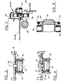
- Figure I is a simplified fragmented top plan view of a rail mounted loading apparatus according to the invention, shown on a portion of a movable rail bed, with portions of the apparatus shown broken away for clarity,
- Figure 2 is a simplified fragmented side elevation of the apparatus of Figure 1, drawn at a larger scale than Figure 1, the apparatus being shown in full outline in a lowered position and partially in broken outline in a raised position,
- Figure 3 is a simplified fragmented transverse section generally on line 3-3 of Figure 2, showing swivellable mounting means,
- Figure 4 is a simplified fragmented transverse section generally on line 4-4 of Figure 2, showing swivelling means,
- Figure 5 is a simplified top plan of a second embodiment of the invention, shown in full outline in a lowered and retracted position, and partially in broken outline in extended positions, with anchoring means thereof shown in broken outline extended,
- Figure 6 is a simplified fragmented side elevation of the second embodiment of Figure 5, drawn at a larger scale than Figure 5, the apparatus being shown in full outline with a portion retracted, and partly in broken outline with the portion extended and/or raised,
- Figure 7 is a simplified fragmented section generally on line 7-7 of Figure 6 showing an advancing cylinder and a portion of the body and conveyor assembly,
- Figure 8 is a simplified transverse section on line 8-8 of Figure 6 showing alternate anchoring or levelling means.
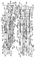
- Figure 9 . is a simplified side elevation of a third embodiment of the invention shown in a retracted and lowered configuration,
- Figure 10 is a simplified top plan of the third embodiment shown in the retracted configuration of Figure 9,
- Figure 11 is a simplified section on line II-II of Figure 9,
- Figure 12 is a simplified fragmented side elevation of a forward portion of the third embodiment shown in an extended configuration,
- Figure 13 is a simplified fragmented detail section on line 13-13 of Figure 12,
- Figure 14 is a simplified fragmented detail section on line 14-14 of Figure 12, and
- Figure 15 is a simplified and sectioned side elevation at enlarged scale of a forward portion of a primary conveyor assembly and associated penetrating means.
- Figure 16 is a simplified diagram of compound oscillating means using hydraulic cylinders in series.
- Referring mainly to Figures I and 2, a rail mounted
loading apparatus 10 according to the invention is shown supported on a pair of spacedrails 12 of a railroad track carried on amovable rail platform 14 which has aforward end 15. Theplatform 14, which can be of the type described in Canadian Patent #719,987, is supported on theground 16 and, by known means, is advanced in direction of anarrow 17 towards a muck pile or loose material to be excavated, not shown. Therails 12 are securely fixed to theplatform 14 to withstand penetration forces as will be described, and if the platform is not used, alternative means of securely fixing the rails to theground 16 is required. - The
apparatus 10 has abody 20 supported on front and rearwheeled bogies rails 12. Thewheels 25 and associated bogies serve as mobile mounting means for supporting and permitting movement of the body on a supporting surface, namely the rails. The apparatus has aconveyor assembly 27 mounted on the body and adapted to transport material from afront portion 29 of the conveyor assembly to arear portion 30 thereof along alongitudinal conveyor axis 32. The conveyor assembly has aconveyor supporting frame 34 which is divided into front and rear conveyor frames 35 and 36 which are hinged together at a horizontal transverseconveyor hinge axis 38. Thus, the front portion of the conveyor assembly is hinged to the rear portion thereof for swinging about a hinge at thehinge axis 38. The conveyor assembly also includes achain conveyor 40, in which four endless parallel conveyor chains, shown in broken line, extend around front andrear sprocket shafts - Parallel elevating cylinders 47 and 48 extend between the
front portion 29 of the conveyor assembly and thebody 20 and serve as elevating means so that, when actuated, the front portion swings about thetransverse conveyor axis 38 and raises or lowers theportion 29. Connections of the cylinders 47 and 48 to thefront portion 29 and thebody 20 are partial universal connections to permit swivelling of the conveyor as will be described. The cylinders 47 and 48 serve as forward elevating means extending between the front portion and structure associated with the rear portion, in this instance the body. A penetratingmeans 50 according to the invention is hinged adjacent an extreme forward end of the front portion of the conveyor assembly for limited rotation about a horizontaltransverse penetrator axis 53 which is disposed normally to thelongitudinal conveyor axis 32 and is also concentric with an axis of rotation of the sprocket shaft 4L The penetrating means 50 is a shallow wedge-like apron or shovel that is forced into the muck pile and has a reinforcedpenetrator tip 52 to resist wear as it is forced into the muck pile. A similar penetrating means is described in greater detail with reference to Figure 16. The penetrating means also has upwardly extendingarms oscillating cylinders arms brackets oscillating cylinders arms lower angles angles front portion 29. The means 50 can also be made to oscillate at particular frequencies through relatively small angles as will be described. - With reference also to Figures 3 and 4, the body 20 has
chassis members rear bogies outer frame 74 connecting the chassis members which carries theconveyor assembly 27 and structure associated therewith. Thus, theouter frame 74 houses apower plant 73 for moving the apparatus along the rails as required, and also for powering theconveyor assembly 27 and actuating the various hydraulic and electrical components. Themember 71 and thebogie 23 are mounted for relative swivelling movement therebetween and are coupled together through aswivel bearing assembly 77 having aswivel axis 78 as seen in Figure 3. As seen best in Figures I and 4, aswivel cylinder 79 extends transversely between acentral portion 76 of thebody 20 and theouter frame 74 and is adapted to swing the outer frame relative to the bogies about theswivel axis 78. Thebogie 22 is connected to thecentral portion 76 of thebody 20 by a bogie swivel bearing 80 andcylinder body 81 of thecylinder 79 is connected by trunnion mounts to theportion 76. Thechassis member 70 has a plate-like horizontal base with arectangular opening 69 to accept thecentral portion 76 therein as a sliding fit. Theopening 69 is of sufficient size to provide clearance for relative limited lateral swinging movement of theportion 76. As the combination of theframe 74 and theconveyor assembly 27 is swung about theswivel axis 78, thefront portion 29 swings between limits 29.1 and 29.2 and therear portion 30 swings between limits 30.1 and 30.2 as shown in Figure 1. If necessary, stabilizers, not shown, can be provided to extend downwardly from outer portions of theframe 74 to engage the ground to prevent over turning of the apparatus when the upper portion approaches the limits of swinging relative to the chassis. Thus, it can be seen that the conveyor assembly is mounted on the body for limited lateral swinging about an essentially vertical swivel axis so as to permit collection of material disposed to one side of the front portion of the conveyor when in a central position. - An advancing
cylinder 82 has a cylinder upper end connected to abracket 83 connected to thechassis 70, and an extensible andretractable piston rod 84 connected to areleasable rail clamp 85 which can be clamped onto anadjacent rail 12 or adjacent rail platform structure. Any clamp of sufficient gripping force can be used, and is preferably operated remotely. Alift cylinder 88, broken outline, extends between the advancingcylinder 82 and the body so as to raise therail clamp 85 when required, so as to avoid interference with obstructions adjacent the ground, and structure associated with the rail when theapparatus 10 is mobile. A similar advancingcylinder 90, and respective lift cylinder, not shown, are provided on an opposite side of the body to engage the opposite rail or equivalent with asimilar rail clamp 91. The advancing and lift cylinders are connected to respective structure through partial universal joints or equivalents to permit limited lateral and vertical swinging of the cylinders. - It can be seen that, when the two rail clamps are clamped on appropriate rails, and the advancing
cylinders apparatus 10 is moved in direction of thearrow 17 so that the penetratingmeans 50 is forced into the muck pile, and as will be described, when themeans 50 is oscillated, material is fed at relatively low energy requirements onto the conveyor. The apparatus is thus moved forwardly independently of tractive effort from the wheels, and thus the wheels could freewheel while the advancing cylinders are actuated, thus eliminating scuffing and drive strain wear . It can be seen that the rail clamps 85 and 91 serve as anchoring means which are adapted to cooperate with surroundings adjacent the apparatus, that is to releasably engage rigid structure, ie. the rails, so as to resist reaction to penetration forces generated on the penetrating means, or in other words, to permit the advancing means to force against the anchoring means to drive the penetrating means into the muck pile. The advancingcylinders - In operation, referring mainly to Figures 1 and 2, the
movable rail platform 14 is positioned so that the forward end thereof 15 is closely adjacent the muck pile, and theapparatus 10 moves, for example by power applied to thewheels 25, so that thefront portion 29 extends beyond theend 15 to be close to the muck pile. The elevating cylinders 47 and 48 are actuated so that a lower surface of the penetratingmeans 50 is closely adjacent theground 16 so that themeans 50 can approach a lower portion of the muck heap. The advancing cylinders are extended to full extension and the respective lift cylinders are actuated to position the rail clamps 85 and 91 over theappropriate rail 12, the rail clamps then being actuated so that they grip therails 12. The advancingcylinders penetrator axis 53, ie. by swinging the penetrating means up and down through theangles front portion 29 can be raised by extending the elevating cylinders 47 and 48, so that the penetrating means penetrates the muck heap at a higher elevation, thus reducing load on the penetrating means and facilitating entry. Material disturbed by oscillations of themeans 50 falls onto themeans 50 and is pushed rearwardly onto the conveyor and moved upwardly along theportion 29 onto theportion 30 from where it is discharged into a waiting conveyance, not shown, from a rear end of therear portion 30. The rear end of the conveyor assembly sweeps over the conveyance during the stroke of the advancing cylinders and distributes material generally evenly in the conveyance. When thecylinders - The oscillations permit the tip of the penetrating means to penetrate into the muck heap in an essentially continuous manner, thus producing an essentially continuous stream of material falling onto the conveyor assembly, and essentially eliminating the intermittent feeding of material onto the conveyor assembly which is inherent in prior art apparatus using scrapers, buckets, etc. If the cylinders 47 and 48 are not actuated to raise the penetrating
means 50, themeans 50 follows a path dependent on inclination of the rails and this improves control of the angle of the resulting bed. The penetrating means can be oscillated at an optimum frequency, or a combination of frequencies as will be described with reference to Figure 16, and the penetrating means can be raised as required to enhance material removal without use of the power train or scuffing of the wheels and rails. A typical range of frequencies might be between ten and several thousand cycles per minute for a total amplitude swing of between zero and thirty ' degrees, or alternatively a maximum total tip displacement of about twenty to thirty centimeters. It would be usual to combine the higher frequency with the smaller amplitude and vice versa. - A second
embodiment loading apparatus 130 differs from theloading apparatus 10 of Figures 1 through 4 by substituting a track laying or crawler track mounting means 132 for thewheels 25 andrailroad track 12. Also, because the crawler tracks 132 can be positioned relatively easily on theground 131, the swivelling conveyor assembly of Figures 1 through 4 has been replaced with a non-swivellingalternative conveyor assembly 134, which also has other differences as will be described. Theapparatus 130 has abody 135 mounted on the crawler tracks 132 and a plurality of roller bearing assemblies 137 which support the conveyor assembly to permit longitudinal movement of the conveyor assembly as will be described with reference to Figure 7. Theconveyor assembly 134 has alongitudinal conveyor axis 133 and aconveyor supporting frame 129 carrying a conveyor, theframe 129 having front andrear portions conveyor hinge axis 142. Therear portion 140 is carried on a longitudinal rail or ram means 141 complementary to the bearing assemblies 137 as will be described with reference to Figure 7. The ram or rail means 141 is mounted in the bearing assemblies 137 which serve as a complementary ram socket or linear bearing guide means 148. The resulting combination of ram and socket permits longitudinal movement of the conveyor supporting frame in direction of anarrow 144 from a retracted or rearmost position of the conveyor assembly as shown, to a foremost or extended position of the conveyor assembly, not shown. An extended position of an equivalent ram means of a third embodiment is shown in Figure 12, and will be described later. The body contains a suitable motor and hydraulic pumps, and other known equipment for driving the crawler tracks, and for operating various hydraulic and electrical equipment as will be described. - The body carries a pair of parallel
conveyor advancing cylinders rear portion 140 of the conveyor assembly. Thus, from the position shown in Figure 6, actuation of thecylinders arrow 144 so that theforward portion 139 attains a position 139.1 when the advancing cylinders are fully actuated. Therear portion 140 moves with thefront portion 139 and moves along the body until an extremerear end 151 of theportion 140 becomes close to a rear end of the body. Arear elevating cylinder 149 extends between a rear portion 150 of the ram means 141 and therear portion 140, and can raise the rear portion to a raised position 140.1, as shown in Figure 6 to provide clearance for theend 151 of the conveyor over a conveyance, not shown, which can be positioned to receive material falling from the conveyor. Thus, the rear portion is adapted for swinging about theconveyor hinge axis 142 and, because thecylinder 149 is mounted on the ram means 141, it can accomodate the longitudinal sliding of the rear portion when the advancingcylinders - Referring also to Figure 7, which shows one side of the
rear portion 140, one typical bearing assembly 137 of the several on each side is described. The assembly 137 has upper and lower horizontally-journalled rollers means 141 being hardened tracks which are engaged by the rollers to permit longitudinal movement and to prevent vertical movement of therear portion 140. A verticallyjournalled roller 143 engages an outer vertical face of themeans 141 to prevent lateral movement of therear portion 140. Therollers means 141 to control lost motion and aceomodate wear, and adust seal 145 sweeps a face of therear portion 140 to reduce bearing contamination. A series of similar bearing assemblies 137 are mounted on each side of thebody 135 and are also spaced along the body to support the rear portion in all positions and thus provide the linear bearing 148 which provides the ram socket for mounting the ram means 14L - Referring mainly to Figure 6, a penetrating
means 152 is mounted adjacent thefront portion 139 and is hinged adjacent an extreme forward end of the front portion for limited rotation about a horizontaltransverse penetrator axis 154 disposed normally to thelongitudinal axis 133 of the conveyor. The means 152 has apenetrator tip 156 which is reinforced to reduce wear when forced into a muck pile during mucking and is similar to themeans 50 of Figure L A pair of spacedoscillating cylinders forward portion 139 andrespective arms cylinders axis 154 through an arc shown by undesignated arrows. A pair of parallel elevating cylinders 163 and 164 extend between thefront portion 139 and aforward portion 161 of structure movable with the ram means 141, so as to swing the front portion about theaxis 142. The elevating cylinders 163 and 164 thus follow longitudinal movement of the conveyor and, for convenience, the combination of thecomplete conveyor assembly 134, the ram means 141, the penetrating means 152 and thecylinders body 135 in response to actuation of thecylinders - When the
rear portion 140 is in a rearmost position as shown, extension of the elevating cylinders 163 and 164 swings the front portion from a retracted lowered position, shown in full outline and designated 139 in Figure 6, to a retracted raised position, shown in broken outline and designated 139.2, in which the penetrating means is in a similar retracted raised position 152.2. However, if the advancing cylinders are actuated when the front portion is lowered, the front portion and means 152 assume extended lowered positions 139.1 and 152.1, broken outline, from which when the front portion is raised, the front portion assumes an extended raised position 139.3, shown in broken outline. - The
body 135 has twooperator positions operator position 166 can be used when the apparatus is being moved, ie. when positioning the apparatus prior to mucking, and theposition 167 is used primarily when loading or as desired. Thebody 135 has a pair of laterallyextensible rams rock face 174 defining opposite side walls of the tunnel so as to essentially prevent movement of the body during mucking. Thebody 135 also has a pair of longitudinallyextensible support legs transverse beam 180 adjacent a rear of thebody 135 and, if required, a similar transverse beam, not shown, can be mounted adjacent the front of the apparatus and a second pair of support legs, not shown, can be fitted. - In operation, the
loading apparatus 130 functions similarly to theapparatus 10 of Figures 1 through 4, with the exception that the anchoring means, namely the laterally extendingrams legs body 135 to adjacent fixed structure, ie. the adjacent rock, and thus the body itself does not move whilst the penetrating means and conveyor is advanced into the muck pile. This contrasts with the previous embodiment where the whole apparatus, with the exception of the anchoring means, moves as the penetrating means is advanced into the muck pile. Similarly to the first embodiment, in the second embodiment the advancing means, ie. thecylinders - A typical sequence of operation for the
apparatus 130 is as follows. The operator, in theposition 166, actuates the crawler tracks 132 until the penetrating means, in the lowered retracted position as shown in full outline in Figure 6, is closely adjacent the muck pile. If heavy mucking is expected, the laterally extendingrams rock wall 174, and if inclination of the body requires adjusting, thesupport legs position 167 and actuates the advancingcylinders front portion 139 is lowered as shown in Figure 6. As the advancing cylinders move theconveyor assembly 134 forwardly, the penetrating means advances into the muck pile, and when a particular resistance to penetration is felt, theoscillating cylinders axis 145 to facilitate penetration into the muck pile. As the penetrating means advances further into the muck pile, and additional resistance is experienced, if necessary the elevating cylinders 163 and 164 can be extended to raise thefront portion 139, so that the penetrating means describes a higher path through the muck pile, thus reducing load on the penetrating means. Muck falling onto the penetrating means is moved rearwardly onto the conveyor, to pass up theforward portion 139, along therear portion 140 and is discharged from the back of therear portion 140 onto a waiting conveyance, not shown. Therear portion 140 moves axially, and thus distributes material axially into the waiting conveyance. - When the advancing cylinders reach the end of their stroke, the penetrating means is activated so as to essentially empty material off the penetrating means. The advancing cylinders are then retracted so that the conveyor assembly moves rearwardly and the front portion is again lowered to assume the full outline position shown in Figure 6. The above cycle is repeated as needed until the muck pile is essentially removed, the body remaining stationary throughout to relieve the power train of wear. The laterally extending rams and advancing cylinders are then retracted and the crawler tracks are actuated to move the
apparatus 130 forwardly, so as to position the penetrating means closely adjacent remaining portions of the muck heap once again. The laterally extendingrams 170 and 171 and thesupport legs - Thus, it can be seen that the laterally extending rams serve as anchoring means mounted on the body and adapted to extend outwardly therefrom to engage an adjacent surface of the surroundings to prevent esentially movement of the body relative to the surface. Thus the rams are adapted to cooperate with the surroundings adjacent the apparatus to resist reaction to penetration forces generated on the penetrating means. Also, the
conveyor advancing cylinders cylinders oscillating cylinders cylinders - In summary, it can be seen that a method of loading material according to the invention is for use with an apparatus having a body and a conveyor assembly mounted on the body and adapted to transport material from a front portion of the conveyor to a rear portion thereof along a longitudinal conveyor axis. The front portion has a penetrating means and the method is characterized by: advancing the penetrating means into the material to be loaded, and, when required, simultaneously rotationally oscillating the penetrating means about a horizontal transverse axis disposed normally to the longitudinal axis to facilitate loading of material onto the conveyor. To overcome resistance to penetration, prior to advancing the penetrating means into the material to be loaded, an anchoring means is anchored relative to the surroundings and is forced against to overcome the resistance to penetration of the material. In the first embodiment, after the anchoring means is anchored relative to the surroundings, the remainder of the apparatus is moved by advancing means relative to the anchoring means, thus forcing the penetrating means into the muck heap. In the second embodiment, the body is anchored relative to the surroundings and the conveyor assembly is moved forwardly relative to the body to advance the penetrating means into the muck heap.
- A
third embodiment 210 of the invention differs from the two previously described embodiments by providing a secondary conveyor assembly which remains fixed during mucking, thus discharging material at a fixed locating during one complete stroke of the penetrating means. Similarly to the second embodiment herein, the conveyor assembly carrying the penetrating means moves relative to a fixed body during the complete stroke and is a portion of an equivalent excavating assembly as will be described. - The
third embodiment 210 of the invention has a supportingbody 212 carried on forward and rear pairs ofwheels seat 217, provided with controls to control, amongst other things, anelectrical power unit 218 for use at an excavation face and area where exhaust, heat or noise produces problems. Aseparate power unit 216, which is typically an internal combustion engine, is for use where exhaust, etc., are not problems. Alternatively the apparatus can be powered by one source of power. - The apparatus has primary and
secondary conveyor assemblies 221 and 222 respectively, the assembly 221 having front andrear portions assembly 222 having front andrear portions rear portion 225 of the primary conveyor assembly is disposed above theforward portion 227 of the secondary conveyor assembly to permit material to fall from the primary to the secondary conveyor assemblies. The primary conveyor assembly has aninclined chain conveyor 229 having fourchains 230 connecting a plurality of flights, some of which are shown in broken outline, theconveyor 229 being similar to those conveyors as commonly used in mucking operations. Thechain conveyor 229 has awidth 231 which is considerably wider thanwidth 232 of the secondary conveyor assembly, which has abelt conveyor 233 as commonly used in mines for transporting muck. Both conveyors pass through conveyor drive means so that upper surfaces of the conveyors move rearwardly in a general direction of anarrow 237. The front orforward portion 224 is inclined at anangle 235 about 15°, and therear portion 225 is inclined at ashallower angle 236, typically between 1° and 5°. Thus material moving up the primary conveyor is subjected to a rapid climb initially on the forward portion to reduce length of the conveyor, and is then transported essentially horizontally on the rear portion for discharge onto theforward portion 227 of the secondary conveyor assembly below, the discharged material being guided by aninclined tapering funnel 234. - A penetrating means or
penetrator 238 has aforward tip 239 and is mounted adjacent theforward portion 224 of the primary conveyor assembly for swinging about atransverse penetrator axis 240 disposed horizontally and normally to the longitudinal axis 19 in the top plan view of Figure 10. The penetrator axis is coincident with an axis of a forwardconveyor sprocket shaft 241 and permits the penetrating means to swing through an arc 242 from a horizontal datum position as shown in full outline to a downwardlyinclined position 244 disposed to the horizontal at anangle 245, about 10°, through to an upwardly inclined position 247 disposed to the horizontal at anangle 248 about 30°. For some applications theangle 245 could be equal to theangle 248, i.e. about 30°. A pair ofpenetrator moment arms penetrator actuating cylinders 254 and 255 respectively which have opposite ends cooperating withside members penetrator cylinders 254 and 255 swings the penetrating means through theangles - The apparatus also includes a
ram member 258 extending rearwardly and axially from aprimary conveyor support 260, which supports a forward end of theportion 225 and a rear end of theportion 224 of the primary conveyor assembly. Thebody 12 has aram socket 262 which is complementary to the ram member and is adapted to receive the ram member therein. The socket is mounted on the body so as to be disposed generally axially, that is along the longitudinal axis 219, and horizontally as viewed in the side elevation of Figure 9. As will be described with reference to Figure 13, the ram member and ram socket are generally rectangular in cross section and provide a sturdy support for ensuring axial movement of the ram member and primary conveyor assembly as will be described. As best seen in Figures 10 and 12, the ram rnmber has forward andrear ends conveyor elevating cylinders forward end 264, and aram actuating cylinder 269 connected at therear end 265. Theprimary conveyor support 260 also extends upwardly from theforward end 264 of the ram member to anupper hinge pin 276 to which is connected to theforward portion 224 of the primary conveyor to permit swinging thereabout relative to a conveyor hinge concentric with thepin 276. Thus thesupport 260 supports adjacent portions of the primary conveyor assembly at the conveyor hinge. The elevatingcylinders side members forward portion 224 remote from thehinge pin 276 so that extension of the elevatingcylinders forward portion 224 about thepin 276 through anarc 278 to anuppermost position 279, shown in broken outline in Figure 9 only, in which theforward portion 224 is essentially horizontal. Thus theforward portion 224 is hinged to therear portion 225 to permit relative swinging therebetween about the hinge, and thecylinders forward portion 224 and the ram member to swing theportion 224 relative to theportion 225 to vary height of thetransverse axis 240. When theforward portion 224 is in theuppermost position 279 and the penetrating means is fully elevated relative to theportion 224 thetip 239 of the penetrating means assumes anuppermost position 281 which is the highest portion of the apparatus. Therein actuatingcylinder 269 has aninner end 283 secured adjacent a rear portion of thebody 212, and anouter end 284, i.e. an end of the piston rod thereof, secured to therear end 265 of theram member 258 so that actuation of the ram actuating cylinder moves the ram member axially along the ram socket. Other telescoping means equivalent to the ram cylinder are known and all serve as an advancing means to move the primary conveyor assembly. - As best seen in Figure 14, a conveyor supporting frame 282 of the
rear portion 225 of the primary conveyor assembly has a pair of parallel side members 285 and 286, each member having first guide means 287 extending along both sides of the conveyor. Thebody 212 has an upper support 288 having a second guide means 289 to engage the first guide means 287 of the primary conveyor assembly to permit essentially axial movement between theconveyor assemblies 221 and 222 and also to support therear portion 225 of the primary conveyor assembly above the secondary conveyor assembly. Thus, extension of theram member 258 produces concurrent forward movement of theforward portion 224 and therear portion 225 of the assembly 221. Thus it can be seen that the ram socket and second guide means, which are both fixed and carried on thebody 212, support theram member 258 andrear portion 225 of a movable excavating assembly 291 which includes the complete primary conveyor assembly 221, the penetrating means 238, theprimary conveyor support 260, thepemetrator cylinders 254 and 255 serving as oscillating means, elevatingcylinders ram member 258 serving as extension means. This total excavating assembly is movable "en masse", i.e. all together as one connected assembly, relative to the body and this, permits the penetrating means 238 to be forced into a muck heap at a particular angle whilst thebody 212 and secondary conveyor assembly remain stationary. - Thus, in summary, the excavating assembly is supported on the extension means which extends forwardly from the body and supports the primary conveyor assembly to permit essentially axial movement between the primary and secondary conveyor assemblies. The extension means includes the ram means cooperating with the primary conveyor assembly and the body to permit longitudinal axial sliding movement of the primary conveyor relative to the body so that the penetrating means is forced into the material the ram means concurrently supporting the forward portion of the primary conveyor. The excavating assemblies 165 of Figure 5 and 291 of Figure 12 are essentially equivalent and permit movement of the penetrating means relative to a fixed body.
- The
wheels body 212 and eliminate resilience effect of the tires and suspension by raising the body to relieve weight from the wheels during the mucking operation, and to provide forward movement for the penetrating means by extending the excavating assembly 291 as described. Such raising is accomplished by providing first andsecond pairs ram member 258, so as to accommodate terrain or other variables in the mine. In this way, when thebody 212 is set by the legs in a desired attitude, the ground under the muck heap can be scraped by the penetrating means 238 in a desired plane thus producing a final road bed of desired inclination. This reduces the irregularities in the final road bed that are commonly produced by prior art machines, some of which excavate whilst being supported on tires or tracks, where suspension resilience or irregularities in the existing road bed reduce control of a scraper or equivalent. Clearly, in prior art machines where a scraper, etc., extends or overhangs considerable forwardly from wheels or tracks, any unevenness in the existing road bed is magnified at the scraper due to the overhang effect. Thus, weight is relieved, or completely eliminated from the mobile mounting means and reaction to thrust on the excavating assembly 291 is resisted by the four legs. In Figure 12, one leg of thefirst pair 293 is shown extended in broken outline and has a point to engage the ground to resist mucking forces to serve as anchoring means. - A pair of similar laterally
extensible rams body 212 and have axes of extension andretraction acute angles extensible portions arrow 237 and it can be seen that the acute angle of the rams contacting the walls resists slipping more effectively than if the rams were at right angles to the wall. Thus, the apparatus includes a first pair of extensible rams which are mounted on the body and, where appropriate, are adapted to extend generally laterally and horizontally from the body to engage adjacent oppositely facing surfaces to augment restraint of the apparatus against movement, and thus serve as anchoring moans. - A pair of similar upwardly
extensible rams ram 308 is mounted on a knuckle joint 310 at a lower end thereof to permit swinging of the ram within a partiallyconical envelope 311 so as to vary angle of contact of the ram with the surface with which it is engaged. Aswing cylinder 312 extends between thebody 212 and the ram to control angle of theram 308. When the first and second pairs oflegs rams body 212 is securely restrained within the mine opening. Thus, extension of the rams augments restraint of the apparatus against movement by increasing load on the means bearing weight of the apgaratus, in this case, the first and second pairs oflegs - The
ram menber 258 andram socket 262 are generally metrical about the axis 219, not shown, and thus one portion only will be described. Theram member 258 has a generally rectangular box section having four plate members, three of which are shown, namely parallel upper andlower plate members vertical plate member 323 extending between themembers members member 323 and are provided with wear strips orrails ram guide roller 329 fitted between the wear strips. Theram socket 262 has upper andlower wall members side member 333 carrying an inwardly extendingspindle 334 which journals therolls 329 thereon, the spindle having alubrication passage 335 to lubricate theroller 329. Opposite sides of the ram member and ram sockets are similar and it can be seen that the considerable loads existing between the ram member and ram socket are carried on the wear strips and respective rollers. At least four pairs of theram guide rollers 329 are fitted in the ram socket to support and guide the ram member as it extends and are also shown in broken outline in Figures 9, 10 and 12. The rollers and rails are defined as roller means to mount the ram for axial movement relative to the ram socket. - The primary conveyor assenbly 221 and respective supports are generally symmetrical about the axis 219, not shown, and thus one portion only will be described. The
rear portion 225 of the assembly 221 has arear support spindle 341 extending non- rotatably between the side members and journalling thereon a rearconveyor sprocket shaft 343 carrying aconveyor sprocket 344. Thespindle 341 has an outer end adjacent the side member 285 journalling aconveyor guide roller 347 thereon. The support 288 of thebody 212 has a grooved side wall 352 having upper and lower wear surfaces orrails guide roller 347. Thus, the guide roller is restrained against vertical movement to resist forces imparted to the primary conveyor assembly during mucking, etc., but is free to move axially as the conveyor assembly 221 extends. An opposite end of thespindle 341 is similar and thus it can be seen that theconveyor guide rollers 347 serve as the first guide means 287 for the rear portion of the primary conveyor assembly, and the grooved side walls and rails serve as the second guide means 289 of the body to engage the first guide means. The guide rollers and rails are defined as roller means associated with the first and second guide means to mount the primary conveyor assembly for movement relative to the supporting body. - The penetrating means 238 has upper and
lower plates concave wall 364 and side walls, not shown, so as to form a closed box-like assembly. Alower member 360 extending between theside members forward portion 224 terminate at an upwardlycurved lip 366 which, similarly to thewall 364, is concentric with thecommon penetrator axis 240 and axis of theconveyor sprocket shaft 241 of the primary conveyor. One of the conveyor chains 280, connected to the flights, not shown, for transporting materials up the primary conveyor, passes around a sprocket, not shown, mounted on theconveyor shaft 241 which is hollow and encloses a fixedspindle 363 which journals theshaft 241 and the penetratingmeans 238. Anupper edge 365 of theconcave wall 364 is shown in a datum position designated 367 in which thelower plate 361 is horizontal, and theangles edge 365 is in an uppermost position, shown in broken outline 365.1, there is sufficient clearance to prevent interference with the chain. Likewise, in the lowermost position of the penetrating means, not shown, theupper edge 365 is no lower than thelip 366 of theundersurface 260. This is to direct muck relatively smothly onto the conveyor and also to reduce ingress of muck between theframe 277 and thechain 230. The penetrating means 50 and 152 of the previous embodiments are generally similar to themeans 238. - In operation, the third embodiment functions generally similarly to the second embodiment as follows.
- The
apparatus 210 with a retracted ram cylinder, moves into a position adjacent amuck heap and drives the penetrating means disposed in the datum position into the muck heap until resistance to penetration is such that the tires are close to the limit of adhesion. The apparatus is stopped and the first and second pairs oflegs extensible rams extensible rams ram actuating cylinder 269 is then extended so as to force the excavating assembly 291 forwardly from the position shown in Figure 9 towards the position shown in Figure 12. The penetrating means is set so as to be generally horizontal to aid penetration, but it can be inclined to accommodate the muck pile characteristics. Also the elevatingcylinders forward portion 224 can be raised by extending thecylinders penetrator oscillating cylinders 254 and 255 are actuated so as to produce suitable rotational oscillations of the penetrating means as previously described. As the penetrating means moves into the muck pile, if the elevating cylinders remain inactive, the penetrating means follow a desired path which is dependent on inclination of the ram socket, and is independent of surface undulations and resilience of the suspension because the supportinglegs - Each of the three embodiments shown have different mobile mounting means, for example railroad wheels of the first embodiment, endless crawler tracks of the second embodiment and rubber-tired wheels of the third embodiment. All are equivalent and can be substituted as required.
- A
second embodiment 371 of an oscillating means is for use in muck piles of particularly difficult loading characteristics and differs from the previously described oscillating means by providing apparatus and method which superimposes one type of oscillation upon another type of oscillation of the penetrating means so as to provide a compound oscillation of two distinct oscillations, i.e. at least two modes of oscillation which can be applied to any penetrating means as described. The penetrating means 238 of Figure 9 is shown hinged for oscillation about thepenetrator axis 240 adjacent theforward portion 224 of the primary conveyor assembly 221. Thepenetrator moment arm 251 extends from theaxis 240, but theoscillating cylinder 254 of Figure 9 is eliminated and a separatecompound oscillation apparatus 373 is substituted. Theapparatus 373 includes a large strokehydraulic cylinder 375 having a first portion orbody 376 hinged to theforward portion 224, and a second portion orpiston rod 378 extending therefrom. Therod 378 carries asmall stroke cylinder 380 aligned therewith and having a respectiveshort piston rod 382 connected to an outer end of themoment arm 251, It can be seen that thecompound oscillating apparatus 378 includes large and small stroke hydraulic actuators by cylinders arranged in series with each other and extending between the primary conveyor assembly and thearm 251 to provide means equivalent to those as previously described for rotationally oscillating the penetratingmeans 50. - In operation, the
apparatus 373 receives two distinct sets of hydraulic signals for the two cylinders, but these sets are usually related. Thecylinder 375 receives large volume, low frequency, flow signals to swing themeans 238 through theangles 238 through theangles cylinder 380 receives relatively lower volume, higher frequency, flow signals to oscillate themeans 238 throughsmaller displacements 384 at thetip 239 shown in broken outline at the three particular positions, but of course the higher frequency oscillations are applied to the tip for the full swinging between the upper and lower extreme positions.Total displacement 385 of the tip due to actuation of thecylinder 375 is of the order of thirty centemeters maximum as previously described, whereas thedisplacement 384 could be less than one centimeter in scene instances. The frequency of oscillation of thecylinder 375 can vary from zero to about one- hundred cycles per minute, depending on amplitude, and the frequency of thecylinder 380 can vary between zero and several thousand cycles per minute, also depending on the amplitude.
Claims (16)
- L A mobile loading apparatus (10, 130, 210) having a body (20, 135, 212), and a conveyor assembly (27, 134, 221) mounted on the body, the conveyor assembly being adapted to transport material from a front portion (29, 139, 224) of the conveyor assembly to a rear portion (30, 140, 225) thereof along a longitudinal conveyor axis (32, 133, 219), the apparatus being characterized by:(a) advancing means (82, 90; 146, 147; 269) cooperating with the conveyor assembly (27, 134, 221) to cause essentially axial movement of the conveyor assembly as a reaction to force from the advancing means,(b) penetrating means (50, 152, 238) mounted adjacent the front portion (29, 139, 224), the penetrating means being adapted to be rotationally oscillated about a horizontal transverse penetrator axis (53, 154, 240) disposed normally to the longitudinal axis (32, 133, 219) to facilitate penetration of the material to be loaded onto the conveyor assembly.
- 2. A loading apparatus as claimed in Claim 1 further characterized by:(a) the front portion (29, 139, 224) of the conveyor assembly being hinged to the rear portion (30, 140, 225) thereof for swinging about a horizontal transverse conveyor hinge axis (38, 142, 276),(b) forward elevating means (47, 48; 163, 164; 267, 268) extending between the front portion of the conveyor assembly and structure associated with the transverse conveyor hinge,
so that actuation of the elevating means swings the front portion about the transverse conveyor axis and raises or lowers the penetrating means. - 3. A loading apparatus as claimed in Claim 1 or Claim 2 further characterised by:(a) the body (20) being mounted on mobile mounting means (25),(b) anchoring means (85, 91) adapted to releasably engage rigid structure (12) adjacent the apparatus,(c) the advancing means being extensible and retractable means (82, 90) and extending between the anchoring means and the body,
so that, as the advancing means is actuated, the apparatus rolls on the mounting means towards the material, thus forcing the penetrating means into the material independently of tractive effort from the mounting means. - 4. A loading apparatus as claimed in any preceding claim further characterised by:(a) the conveyor assembly (27) being mounted on the body (20) for limited lateral swinging about an essentially vertical swivel axis (78) so as to permit collection of material disposed to one side of the front portion (29) of the conveyor when in a central position.
- 5. A loading apparatus as claimed in Claim 1 further characterized by:(a) the conveyor assembly (134, 221) having a conveyor supporting frame (129, 282) carrying a conveyor (230), the supporting frame being movable relative to the body along the longitudinal axis (133, 219) of the conveyor assembly.
- 6. A loading apparatus as claimed in Claim 5 further characterized by:(a) an excavating assembly (165, 291) which includes a ram means (141, 258), the conveyor assembly (134, 221), the penetrating means (152, 238) and an oscillating means (157, 158; 254, 255) for oscillating the penetrating means, the excavating assembly being mounted relative to the body (135, 212) so as to be movable all together relative to the body to enable the penetrating means to penetrate the material to be loaded while the body remains stationary.
- 7. A loading apparatus as claimed in Claim 6 wherein the excavating assembly (165, 291) is further characterized by:(a) the front portion (139, 224) of the conveyor essembly (134, 221) being hinged to the rear portion (140, 225) of the conveyor assembly at a conveyor hinge (142, 276) to permit relative swinging therebetween about a horizontal transverse conveyor hinge axis (142, 276),(b) forward elevating means (163, 164; 267, 268) cooperating with the front portion and the ram means (141, 258) to swing the front portion relative to the ram means.
- 8. A loading apparatus as claimed in Claim 5 or 6 in which the conveyor assembly is a primary conveyor assembly (221) and the apparatus is further characterized by:(a) a secondary conveyor assembly (222) mounted on the body (212) and having front and rear portions (227, 228), the two conveyor assemblies being disposed along the longitudinal conveyor axis (219) so that the rear portion (225) of the primary conveyor assembly (221) is disposed directly above the front portion (227) of the secondary conveyor assembly (222).
- 9. A loading apparatus as claimed in Claim 5, 6 or 8 further characterized by:(a) anchoring means including at least one ram (171, 172; 293, 294, 297, 298, 308, 309) mounted on the body (135, 212) and adapted to extend from the body to engage an adjacent surface (174) of the surroundings to prevent essentially movement of the body relative to the surface,(b) the advancing means including extensible and retractable means (146, 147, 269) extending between the body and the conveyor supporting frame to move the conveyor assembly along the conveyor axis,
so that, as the advancing means is actuated, the conveyor is moved towards the material thus forcing the penetrating means into the material independently of tractive effort from mobile mounting means supporting the body. - 10. A loading apparatus as claimed in Claim I further characterized by:(a) the rear portion (140) of the conveyor assembly (134) being hinged for swinging about a horizontal transverse conveyor hinge axis (142),(b) rearward elevating means (149) extending between the rear portion of the conveyor and structure associated with the transverse conveyor axis,
so that actuation of the elevating means swings the rear portion about the transverse conveyor axis and raises or lowers the rear portion. - II. A loading apparatus as claimed in Claim 1 further characterized by:(a) compound oscillation apparatus (373) adapted to apply, as needed, at least two modes of oscillation to the penetrating means.
- 12. A method of loading material onto a loading apparatus (10, 130, 210), wherein the apparatus has a body (20, 135, 212) and a conveyor assembly (27, 134, 221) mounted on the body and adapted to transport material from a front portion (29, 139, 224) of the conveyor assembly to a rear portion (30, 140, 225) thereof along a longitudinal conveyor axis (32, 133, 219), the front portion having a penetrating means (50, 152, 238), the method being characterized by:(a) advancing the penetrating means into material to be loaded,(b) when required, simultaneously rotationally oscillating the penetrating means about a horizontal transverse penetrator axis (53, 154, 240) disposed normally to the longitudinal axis to facilitate loading of material onto the conveyor.
- 13. A method as claimed in Claim 12 further characterized by:(a) prior to advancing the penetrating means into the material to be loaded, anchoring an anchoring means (85, 91; 171, 172; 293, 294, 297, 298, 308, 309) relative to surroundings (174) and forcing against the anchoring means to overcome resistance to penetration of the material
- 14. A method as claimed in Claim 12 in which the conveyor essembly (134, 221) is mounted for longitudinal movement relative to the body (135, 212), and the method is further characterized by:(a) prior to advancing the penetrating means into the material to be loaded, anchoring the body relative to the surroundings to resist reaction to penetrating forces,(b) moving the conveyor assembly forwardly relative to the body to advance the penetrating means into the material.
- 15. A method as claimed in Claim 12 further characterized by:(a) oscillating the penetrating means in a compound oscillation of two modes of oscillation.
- 16. A loading apparatus as claimed in Claim 1 in which the conveyor assembly includes an endless conveyor, and the apparatus is further characterized by:(a) the forward portion of the conveyor assembly having a forward shaft around which the endless conveyor passes,(b) the horizontal transverse penetrator axis being concentric with the forward shaft.
Priority Applications (1)
| Application Number | Priority Date | Filing Date | Title |
|---|---|---|---|
| EP84304235A EP0166039A1 (en) | 1984-06-22 | 1984-06-22 | Mobile loading apparatus and method |
Applications Claiming Priority (1)
| Application Number | Priority Date | Filing Date | Title |
|---|---|---|---|
| EP84304235A EP0166039A1 (en) | 1984-06-22 | 1984-06-22 | Mobile loading apparatus and method |
Publications (1)
| Publication Number | Publication Date |
|---|---|
| EP0166039A1 true EP0166039A1 (en) | 1986-01-02 |
Family
ID=8192671
Family Applications (1)
| Application Number | Title | Priority Date | Filing Date |
|---|---|---|---|
| EP84304235A Withdrawn EP0166039A1 (en) | 1984-06-22 | 1984-06-22 | Mobile loading apparatus and method |
Country Status (1)
| Country | Link |
|---|---|
| EP (1) | EP0166039A1 (en) |
Cited By (1)
| Publication number | Priority date | Publication date | Assignee | Title |
|---|---|---|---|---|
| GB2622764A (en) * | 2022-06-15 | 2024-04-03 | Atureliya Senake | Subterranean space creation and utilisation solutions |
Citations (6)
| Publication number | Priority date | Publication date | Assignee | Title |
|---|---|---|---|---|
| DD39057A (en) * | ||||
| DE2813202A1 (en) * | 1978-03-25 | 1979-10-04 | Salzgitter Maschinen Ag | Digging shovel incorporating mechanical drive - has teeth projecting from bottom, reciprocated from rear, and may incorporate vibrators |
| DE2256020B2 (en) * | 1972-11-15 | 1980-07-10 | Gewerkschaft Eisenhuette Westfalia, 4670 Luenen | Part-cut route or tunnel boring machine |
| DE1921093B2 (en) * | 1969-04-25 | 1980-10-09 | Gewerkschaft Eisenhuette Westfalia, 4670 Luenen | Self propelled excavator and loader - has cutter drum gearbox forming part of excavator boom |
| DE2906793B2 (en) * | 1979-02-22 | 1981-02-26 | Bochumer Eisenhuette Heintzmann & Co Gmbh, 7570 Baden-Baden | Abutment for tunneling machines |
| WO1983002471A1 (en) * | 1982-01-11 | 1983-07-21 | Rolf Mannbro | Vibrator unit preferably for construction works |
-
1984
- 1984-06-22 EP EP84304235A patent/EP0166039A1/en not_active Withdrawn
Patent Citations (6)
| Publication number | Priority date | Publication date | Assignee | Title |
|---|---|---|---|---|
| DD39057A (en) * | ||||
| DE1921093B2 (en) * | 1969-04-25 | 1980-10-09 | Gewerkschaft Eisenhuette Westfalia, 4670 Luenen | Self propelled excavator and loader - has cutter drum gearbox forming part of excavator boom |
| DE2256020B2 (en) * | 1972-11-15 | 1980-07-10 | Gewerkschaft Eisenhuette Westfalia, 4670 Luenen | Part-cut route or tunnel boring machine |
| DE2813202A1 (en) * | 1978-03-25 | 1979-10-04 | Salzgitter Maschinen Ag | Digging shovel incorporating mechanical drive - has teeth projecting from bottom, reciprocated from rear, and may incorporate vibrators |
| DE2906793B2 (en) * | 1979-02-22 | 1981-02-26 | Bochumer Eisenhuette Heintzmann & Co Gmbh, 7570 Baden-Baden | Abutment for tunneling machines |
| WO1983002471A1 (en) * | 1982-01-11 | 1983-07-21 | Rolf Mannbro | Vibrator unit preferably for construction works |
Cited By (1)
| Publication number | Priority date | Publication date | Assignee | Title |
|---|---|---|---|---|
| GB2622764A (en) * | 2022-06-15 | 2024-04-03 | Atureliya Senake | Subterranean space creation and utilisation solutions |
Similar Documents
| Publication | Publication Date | Title |
|---|---|---|
| AU659378B2 (en) | Mobile mining machine having tilted swing axis | |
| US4056284A (en) | Machines for use in mining or tunnelling work | |
| US4648776A (en) | Continuous loading apparatus and method | |
| CN106979015A (en) | A kind of climbing control method of the high inclination-angle development machine with auxiliary climbing apparatus | |
| US4387798A (en) | Cascading conveyor system | |
| US6185847B1 (en) | Continuous shovel | |
| EP0585372A1 (en) | Mobile mining machine | |
| US4240665A (en) | Conveyor mounted vehicle | |
| GB2222995A (en) | Mobile conveyors | |
| US4645266A (en) | Tunnel and gallery excavator | |
| US3982338A (en) | Material handling apparatus | |
| US5577808A (en) | Quarry miner | |
| EP0166039A1 (en) | Mobile loading apparatus and method | |
| DE2160643B2 (en) | Tunneling machine with cutter boom - has inclined trough beneath boom with conveyor on each side | |
| CN115977625A (en) | Cutting big arm with adjustable posture and sliding function and cantilever tunneling machine | |
| US4400897A (en) | Method and railway train for draining a railway track | |
| CN114810113A (en) | Integral telescopic structure and telescopic method of cutting mechanism of heading machine | |
| US3726382A (en) | Loading machine | |
| CN206070609U (en) | Chain type depth adjustable bucket component | |
| CN114150721B (en) | Slagging-off, loading and supporting integrated machine equipment | |
| CN116281238B (en) | Conveying device and conveying method for conveying float coal by following fully-mechanized coal mining machine | |
| CN215979391U (en) | TBM slag removal system and slag removal mechanism thereof | |
| CN219176333U (en) | Tunneling and anchoring integrated machine | |
| CA1191488A (en) | Mobile loading apparatus and method | |
| US3854607A (en) | Traction assist means for loading machines and the like |
Legal Events
| Date | Code | Title | Description |
|---|---|---|---|
| PUAI | Public reference made under article 153(3) epc to a published international application that has entered the european phase |
Free format text: ORIGINAL CODE: 0009012 |
|
| AK | Designated contracting states |
Designated state(s): AT BE CH DE FR GB IT LI LU NL SE |
|
| 17P | Request for examination filed |
Effective date: 19860619 |
|
| 17Q | First examination report despatched |
Effective date: 19870522 |
|
| STAA | Information on the status of an ep patent application or granted ep patent |
Free format text: STATUS: THE APPLICATION IS DEEMED TO BE WITHDRAWN |
|
| 18D | Application deemed to be withdrawn |
Effective date: 19890803 |
|
| EUG | Se: european patent has lapsed |
Ref document number: 84304235.9 Effective date: 19890831 |
|
| RIN1 | Information on inventor provided before grant (corrected) |
Inventor name: BOTTOMLEY, FRANK Inventor name: CRAWSHAY, RICHARD Inventor name: JRADIL, JOHN HELMUT |