EP0089641B1 - Fernsteuerempfänger, insbesondere zur Steuerung von Elektrogeräten - Google Patents
Fernsteuerempfänger, insbesondere zur Steuerung von Elektrogeräten Download PDFInfo
- Publication number
- EP0089641B1 EP0089641B1 EP83102705A EP83102705A EP0089641B1 EP 0089641 B1 EP0089641 B1 EP 0089641B1 EP 83102705 A EP83102705 A EP 83102705A EP 83102705 A EP83102705 A EP 83102705A EP 0089641 B1 EP0089641 B1 EP 0089641B1
- Authority
- EP
- European Patent Office
- Prior art keywords
- voltage
- output
- remote
- integrator
- control receiver
- Prior art date
- Legal status (The legal status is an assumption and is not a legal conclusion. Google has not performed a legal analysis and makes no representation as to the accuracy of the status listed.)
- Expired
Links
Images
Classifications
-
- H—ELECTRICITY
- H04—ELECTRIC COMMUNICATION TECHNIQUE
- H04B—TRANSMISSION
- H04B10/00—Transmission systems employing electromagnetic waves other than radio-waves, e.g. infrared, visible or ultraviolet light, or employing corpuscular radiation, e.g. quantum communication
- H04B10/60—Receivers
-
- G—PHYSICS
- G08—SIGNALLING
- G08C—TRANSMISSION SYSTEMS FOR MEASURED VALUES, CONTROL OR SIMILAR SIGNALS
- G08C19/00—Electric signal transmission systems
- G08C19/16—Electric signal transmission systems in which transmission is by pulses
- G08C19/26—Electric signal transmission systems in which transmission is by pulses by varying pulse repetition frequency
-
- H—ELECTRICITY
- H03—ELECTRONIC CIRCUITRY
- H03J—TUNING RESONANT CIRCUITS; SELECTING RESONANT CIRCUITS
- H03J9/00—Remote-control of tuned circuits; Combined remote-control of tuning and other functions, e.g. brightness, amplification
- H03J9/06—Remote-control of tuned circuits; Combined remote-control of tuning and other functions, e.g. brightness, amplification using electromagnetic waves other than radio waves, e.g. light
-
- H—ELECTRICITY
- H04—ELECTRIC COMMUNICATION TECHNIQUE
- H04B—TRANSMISSION
- H04B14/00—Transmission systems not characterised by the medium used for transmission
- H04B14/02—Transmission systems not characterised by the medium used for transmission characterised by the use of pulse modulation
- H04B14/026—Transmission systems not characterised by the medium used for transmission characterised by the use of pulse modulation using pulse time characteristics modulation, e.g. width, position, interval
Definitions
- the invention relates to a remote control receiver, in particular for controlling electrical devices with the features specified in the preamble of claim 1.
- Remote control receivers of this type are known from FR-A-2180 926, GB-A-20 80 653 or from the specialist publication "The Electronic Engineer", volume 28, No. 12, Dec. 1969, page 76, entry No. 970 and become used in many embodiments. They are generally used, for example, for toy models, radio and television sets or electrical equipment, which also includes in particular electrical lighting. Electromagnetic waves, infrared light or ultrasound waves are used as the transmission medium. The transmission to the remote control receiver takes place either through free space or through the air, but electrical lines or optical fibers can also be used. In addition to amplitude, frequency or also implus width modulation of the transmission signal, an plus frequency modulation is also used for the information transmission.
- the pulses can be modulated onto a carrier or can also be emitted directly, for example as infrared light pulses.
- the lowest possible power consumption for remote control receivers is desirable. This applies not only to battery-operated devices, but also, for example, when the receiver is to be supplied with power from a dimmer circuit for power control of mains-operated consumers, in particular lighting fixtures.
- a dimmer circuit for power control of mains-operated consumers, in particular lighting fixtures.
- Such dimmer circuits regulate the power supply to the consumer by phase-cutting the AC voltage half-waves by means of controlled semiconductor rectifiers (thyristors, triacs).
- thyristors, triacs controlled semiconductor rectifiers
- remote control receivers should reliably recognize the respectively assigned transmission signal, that is to say they should not respond to other signals, for example adjacent modulation frequencies, harmonics of the modulation frequency or even pulse-shaped interference signals.
- Another requirement is that not only is the effort to be kept as low as possible, but also due to the limited space in the devices to be controlled, for example in installation switches with built-in dimmers, the space required with a compact and safe construction is to be kept to a minimum.
- FR-A-2 180 926 and GB-A-20 80 653 describe optical communication systems which are based on the information transmission by infrared light pulses. These devices are used to control electrical devices and are equipped with a sensor for a pulse frequency modulated transmission signal, a selection stage for the modulation frequency and an output stage for switching on the device to be controlled.
- the selection stage has a monostable multivibrator (monoflop) triggered by the modulation pulses, the delay time of which is shorter than the period of the modulation frequency.
- the output of the monostable multivibrator is followed by an integrator which produces a DC voltage that is dependent on the modulation frequency.
- At least one window discriminator connected downstream of the integrator then delivers a signal to the output stage when the DC voltage generated by the integrator at a predetermined modulation frequency lies within an area forming the window.
- the invention has for its object to provide a remote control receiver that improves these known designs of remote control receivers, enables safe selection of the assigned transmission signal in particular with little effort and small space requirements and manages with very low operating performance.
- the invention is based on a remote control receiver of the type mentioned at the outset and is characterized in that in the window discriminator, a voltage divider consisting of two resistors is connected between the integrator output and the positive connection of the operating voltage U B of the receiver or the ground connection .
- the center tap of the voltage divider on the operating voltage side is connected to the input of a C-MOS inverter.
- the center tap of the ground-side voltage divider is connected to an input of a C-MOS gate, the second input of which is connected to the output of the C-MOS inverter and the output of which supplies the signal S.
- the window discriminator is constructed in this way according to the invention from C-MOS logic modules, two of which, according to claim 2, have a positive or negative voltage shift equal to half the window width at the integrator output voltage, for example fluctuations in the operating voltage have practically no influence on the mode of operation .
- a known property of the C-MOS logic modules is used, which consists in the fact that the output voltage of the modules jumps from L to H or vice versa when the input voltage runs through the value of half the operating voltage.
- Such modules also have the advantage of extremely low power consumption in almost all operating states. This also simplifies the power supply accordingly.
- C-MOS logic modules are inexpensive mass-produced items. Together with the simplified power supply, this results in a considerable cost advantage compared to conventional devices of this type.
- OR, NOR, AND, NAND or exclusive OR and NOR logic elements can be considered as logic modules.
- a development according to the characterizing part of claim 6 therefore provides that an integrator is connected downstream of the link.
- the output stage is only influenced if the voltage value is within the window area for a long time.
- the invention can be used in connection with a transmission signal in the field of radio waves or also in connection with ultrasound signals.
- the transmission signal is expedient, particularly with regard to the range limitation, as indicated in claim 7, to use a keyed infrared signal whose keying frequency is the modulation frequency.
- This procedure allows the particularly economical use of a battery-powered handheld transmitter that only has to emit short, powerful infrared flashes with a certain frequency.
- the sensor then consists of an infrared-sensitive diode and an amplifier is connected between the diode and the monostable multivibrator.
- the output stage can be an electronic dimmer circuit with a controllable semiconductor switch, the operating voltage of the receiver being derived from the dimmer circuit.
- the otherwise usually manually set dimmer for brightness control of lamps and power control of other devices can then be easily controlled remotely.
- the components of the remote control receiver then expediently form a compact plug-in module which can be plugged into an electrical installation switch combined with a dimmer. This measure teaches the characterizing part of claim 9.
- the plug-in module can be designed in a similar manner and in a similar size to the fuses arranged in a known manner in a plastic base, which protect the dimmer circuit from excessive inrush currents.
- the components of the remote control receiver can also be built into the actuating plate of an electrical installation switch combined with a dimmer, the infrared-sensitive diode being seated in an opening in the actuating plate and possibly being covered by a window.
- the remote control receiver in a further development of the invention there is also the possibility of accommodating the remote control receiver together with a dimmer circuit or a switching stage in an intermediate connector.
- Such an adapter can then be used by the end user at the desired location. It only needs to be plugged into a socket and receives the connector of the device to be controlled with a socket.
- Another possibility is to remove the remote control receiver with or without the dimmer or switching stage from the adapter by means of a line, the remote control receiver then also being able to sit in a hidden place.
- Other options are a combination of the remote control receiver and dimmer or switch with a table socket or a cord switch or dimmer.
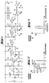
- An infrared-sensitive diode 3 is connected in the reverse direction to the operating voltage U B via a diode 4 with a resistor 5 connected in parallel.
- a coupling capacitor 6 the voltage pulses reach the base of a transistor 12 with a base voltage divider, which consists of resistors 8, 9 and 10 and an additional smoothing capacitor 7.
- a collector resistor 11 and an emitter resistor 14 with a parallel capacitor 13 represent a conventional connection of the transistor 12, which then supplies the pulse-shaped received signal to the non-inverting input of an operational amplifier 17 for further amplification. In the usual way, this has negative feedback from the output to the inverting input by means of the resistors 16 and 19, a capacitor 15 lying in series with the resistor 16 for a weakening of low Fre quenzen ensures.
- An additional capacitor 18 effects frequency compensation of the operational amplifier 17, the output of which is connected to the operating voltage U B via a resistor 20.
- the delay time of the monoflop that is to say the time for which the monoflop is in the unstable state, is set by means of the capacitor 23 and the resistor 22 to a value which corresponds to approximately half the period of the modulation frequency. With each incoming light pulse, the monoflop accordingly generates a pulse of defined duration at the output of the NOR element 24.
- a downstream integrator with a resistor 25 and an integration capacitor 26 then converts the pulse repetition frequency, which is equal to the modulation frequency, into an assigned DC voltage U E at the capacitor 26.
- the values of the components 22, 23 of the monoflop and the components 25, 26 of the integrator are chosen such that a voltage U E at the capacitor 26 results at the modulation frequency to be selected, which voltage is approximately equal to half the operating voltage U B.
- FIG. 2 shows a known transfer characteristic of buffered C-MOS components. It can be seen that the output voltage remains at the value of the operating voltage up to approximately half the operating voltage and then suddenly drops to approximately 0. This drop occurs accordingly at the three operating voltages of 5 V, 10 V and 15 V at 2.5 V, 5 V and 7.5 V shown as parameters. These properties of the C-MOS modules are used in the window discriminator described below.
- the window discriminator consists of two NOR gates 30, 31 and two voltage dividers, each having a resistor 27 and a resistor 28.
- the voltage dividers are fed by the voltage U E of the capacitor 26 and are on the other side at the common reference potential (ground) or at the operating voltage U e .
- the values of the resistors 27, 28 are selected such that the voltage at the tapping points between the two resistors 27, 28 is shifted against the voltage U E by a small amount corresponding to half the window width.
- FIG. 3 shows the output voltage U A at the output of the NOR gate 31 as a function of the input voltage U E at the capacitor 26.
- the input voltage of the NOR gate 30 is small and in any case less than half the operating voltage U B , so that the output of the NOR gate 30 according to FIG. 2 has approximately the value of U B (logic H) .
- the first input of the NOR gate 31 is thus also logic H.
- At the second input of the NOR gate 31 there is also a voltage which is less than half the operating voltage U B , so that the output voltage U A is approximately 0 (logic L) .
- the voltage at the input of the NOR element 30 first reaches the value of half the operating voltage U B , specifically when the voltage U E is smaller than U B / 2 by the amount of voltage drop across the resistor 28 above.
- the voltage at the output of the NOR gate 30 then jumps to about 0 V according to FIG. 2, and since the voltage at the second input of the NOR gate 31 is still less than U B / 2 by about twice the voltage drop across the resistor 28 , the output voltage U A goes to approximately the value of the operating voltage U B , as shown in FIG. 3.
- This state continues with increasing input voltage U E until the voltage at the second input of NOR element 31 also reaches the value of U BI2 . Since a voltage of approximately 0 V is still present at the first input, the output voltage U A jumps back to approximately 0 V.
- the range of the input voltage U E for which the output voltage U A has the value of the operating voltage U B is as shown in FIG specified, referred to as window width.
- the NOR gate 31 is followed by a further integrator with a resistor 32 and a capacitor 33, which has a low-pass function. Only when the output voltage U A has been at the value of the operating voltage U B for a longer period of time does an output inverter 34 deliver a control signal S to the subsequent circuit, for example a dimmer.
- the delay time of the monoflop can be adapted to the respective modulation frequency, as indicated by small crosses, by exchanging the resistor 22.
Landscapes
- Engineering & Computer Science (AREA)
- Physics & Mathematics (AREA)
- Computer Networks & Wireless Communication (AREA)
- Signal Processing (AREA)
- Electromagnetism (AREA)
- General Physics & Mathematics (AREA)
- Computer Hardware Design (AREA)
- Microelectronics & Electronic Packaging (AREA)
- Selective Calling Equipment (AREA)
- Remote Monitoring And Control Of Power-Distribution Networks (AREA)
Priority Applications (1)
| Application Number | Priority Date | Filing Date | Title |
|---|---|---|---|
| AT83102705T ATE25905T1 (de) | 1982-03-24 | 1983-03-18 | Fernsteuerempfaenger, insbesondere zur steuerung von elektrogeraeten. |
Applications Claiming Priority (2)
| Application Number | Priority Date | Filing Date | Title |
|---|---|---|---|
| DE3210710 | 1982-03-24 | ||
| DE19823210710 DE3210710A1 (de) | 1982-03-24 | 1982-03-24 | Fernsteuerempfaenger, insbesondere zur steuerung von elektrogeraeten |
Publications (2)
| Publication Number | Publication Date |
|---|---|
| EP0089641A1 EP0089641A1 (de) | 1983-09-28 |
| EP0089641B1 true EP0089641B1 (de) | 1987-03-11 |
Family
ID=6159105
Family Applications (1)
| Application Number | Title | Priority Date | Filing Date |
|---|---|---|---|
| EP83102705A Expired EP0089641B1 (de) | 1982-03-24 | 1983-03-18 | Fernsteuerempfänger, insbesondere zur Steuerung von Elektrogeräten |
Country Status (5)
| Country | Link |
|---|---|
| EP (1) | EP0089641B1 (el) |
| AT (1) | ATE25905T1 (el) |
| DE (2) | DE3210710A1 (el) |
| ES (1) | ES8402125A1 (el) |
| GR (1) | GR77170B (el) |
Families Citing this family (4)
| Publication number | Priority date | Publication date | Assignee | Title |
|---|---|---|---|---|
| GB2174222B (en) * | 1985-04-27 | 1988-09-21 | Peter Stanley Phillips | Remote operation of an electrical light switch |
| SE455776B (sv) * | 1985-10-24 | 1988-08-08 | Uwe Verken Ab | Temperaturreglerings- och ventilationsanordning for passagerarbefordrande fordon |
| GB2300943B (en) * | 1995-05-19 | 1999-08-18 | Horacio Walter Battle | Remote switching arrangements |
| GB0009962D0 (en) * | 2000-04-25 | 2000-06-14 | Hardwick Michael D | Energy saving |
Family Cites Families (7)
| Publication number | Priority date | Publication date | Assignee | Title |
|---|---|---|---|---|
| US2837642A (en) * | 1953-12-17 | 1958-06-03 | Bell Telephone Labor Inc | Pulse rate discriminator |
| DE1166900B (de) * | 1957-01-02 | 1964-04-02 | Zenith Radio Corp | Anordnung zum Steuern eines elektrischen Geraetes mit Hilfe von in elektrische Signale umgewandelten Ultraschallschwingungen |
| US3558902A (en) * | 1968-01-22 | 1971-01-26 | Everett R Casey | Remote control wiring system |
| US3594588A (en) * | 1969-04-01 | 1971-07-20 | Motorola Inc | Frequency detection system |
| JPS492405A (el) * | 1972-04-18 | 1974-01-10 | ||
| US4200862A (en) * | 1977-01-07 | 1980-04-29 | Pico Electronics Limited | Appliance control |
| IT8005177A0 (it) * | 1980-07-03 | 1980-07-03 | Bermaco Srl | Coppia di fotocellule a raggi infrarossi. |
-
1982
- 1982-03-24 DE DE19823210710 patent/DE3210710A1/de not_active Withdrawn
-
1983
- 1983-03-18 DE DE8383102705T patent/DE3370262D1/de not_active Expired
- 1983-03-18 EP EP83102705A patent/EP0089641B1/de not_active Expired
- 1983-03-18 AT AT83102705T patent/ATE25905T1/de not_active IP Right Cessation
- 1983-03-22 GR GR70842A patent/GR77170B/el unknown
- 1983-03-24 ES ES520959A patent/ES8402125A1/es not_active Expired
Also Published As
| Publication number | Publication date |
|---|---|
| DE3210710A1 (de) | 1984-03-22 |
| ES520959A0 (es) | 1984-01-16 |
| DE3370262D1 (en) | 1987-04-16 |
| EP0089641A1 (de) | 1983-09-28 |
| ATE25905T1 (de) | 1987-03-15 |
| ES8402125A1 (es) | 1984-01-16 |
| GR77170B (el) | 1984-09-10 |
Similar Documents
| Publication | Publication Date | Title |
|---|---|---|
| DE3907410C1 (el) | ||
| EP0393233B1 (de) | Signalübertragungssystem | |
| EP0089641B1 (de) | Fernsteuerempfänger, insbesondere zur Steuerung von Elektrogeräten | |
| EP0139226B1 (de) | Sperrwandler-Schaltnetzteil | |
| EP0198360A2 (de) | Schaltungsanordnung für die Fernspeisung von Teilnehmeranschluss-Endgeräten in Fernmeldeanlagen | |
| EP0339598A2 (de) | Schutzschaltung für kapazitive Lasten | |
| EP0972134B1 (de) | Vorrichtung zur regelung des stromflusses durch einen verbraucher | |
| EP0171470B1 (de) | Einrichtung zur Speisung von Sendern und Empfängern eines Signalübertragungssystems | |
| DE102010024128A1 (de) | Wechselspannungssteller | |
| EP0334431B1 (de) | Schaltungsanordnung zur Erzeugung einer Impuls-Versorgungsspannung für einen Verbraucher aus einer Gleichspannung | |
| EP0058754B1 (de) | Einrichtung zur Einspeisung von digitalen Signalen in ein Leitungssystem | |
| CH666564A5 (de) | Elektronischer sicherheitstemperaturbegrenzer. | |
| DE60206950T2 (de) | Sender zum Übertragen eines Signals mit kontrollierter Signalform über eine Kommunikationsleiste | |
| DE1801404A1 (de) | Schaltungsanordnung zur kontaktlosen Steuerung der Leistung von Wechselspannungsverbrauchern | |
| DE3891380C2 (de) | Verstärker mit vier Transistoren, die in einer Brückenschaltung miteinander verbunden sind | |
| DE3327003C2 (el) | ||
| EP1002363B1 (de) | Vorrichtung zum umsetzen kleiner, von einer nicht-idealen stromquelle an dem eingang der vorrichtung eingeprägter ströme in spannungssignale | |
| DE4011415C2 (el) | ||
| DE1762921A1 (de) | Impulsbreitendiskriminator | |
| DE3940295A1 (de) | Hochfrequenzsender mit geregelter ausgangsleistung | |
| DE4205517C2 (de) | Stromflußgesteuerte Schaltvorrichtung | |
| DE3337205A1 (de) | Infrarot-fernbedienungssystem fuer ein elektrisches geraet, insbesondere einen fernsehempfaenger | |
| WO2016045796A1 (de) | Vorrichtung und verfahren zum steuern einer heizungs- und/oder kühlanlage | |
| DE2020422C3 (de) | Schwellwert Kippschaltung | |
| EP1195932B1 (de) | Hochfrequenzgerät mit Pegelerfassung zur Störunterdrückung |
Legal Events
| Date | Code | Title | Description |
|---|---|---|---|
| PUAI | Public reference made under article 153(3) epc to a published international application that has entered the european phase |
Free format text: ORIGINAL CODE: 0009012 |
|
| AK | Designated contracting states |
Designated state(s): AT BE CH DE FR IT LI LU NL SE |
|
| 17P | Request for examination filed |
Effective date: 19840323 |
|
| RIN1 | Information on inventor provided before grant (corrected) |
Inventor name: BECKER, KLAUS, DIPL.-ING. |
|
| GRAA | (expected) grant |
Free format text: ORIGINAL CODE: 0009210 |
|
| AK | Designated contracting states |
Kind code of ref document: B1 Designated state(s): AT BE CH DE FR IT LI LU NL SE |
|
| PG25 | Lapsed in a contracting state [announced via postgrant information from national office to epo] |
Ref country code: SE Effective date: 19870311 Ref country code: NL Effective date: 19870311 Ref country code: IT Free format text: LAPSE BECAUSE OF FAILURE TO SUBMIT A TRANSLATION OF THE DESCRIPTION OR TO PAY THE FEE WITHIN THE PRESCRIBED TIME-LIMIT;WARNING: LAPSES OF ITALIAN PATENTS WITH EFFECTIVE DATE BEFORE 2007 MAY HAVE OCCURRED AT ANY TIME BEFORE 2007. THE CORRECT EFFECTIVE DATE MAY BE DIFFERENT FROM THE ONE RECORDED. Effective date: 19870311 Ref country code: FR Free format text: THE PATENT HAS BEEN ANNULLED BY A DECISION OF A NATIONAL AUTHORITY Effective date: 19870311 Ref country code: BE Effective date: 19870311 |
|
| REF | Corresponds to: |
Ref document number: 25905 Country of ref document: AT Date of ref document: 19870315 Kind code of ref document: T |
|
| PG25 | Lapsed in a contracting state [announced via postgrant information from national office to epo] |
Ref country code: LU Free format text: LAPSE BECAUSE OF NON-PAYMENT OF DUE FEES Effective date: 19870331 Ref country code: LI Effective date: 19870331 Ref country code: CH Effective date: 19870331 |
|
| REF | Corresponds to: |
Ref document number: 3370262 Country of ref document: DE Date of ref document: 19870416 |
|
| EN | Fr: translation not filed | ||
| NLV1 | Nl: lapsed or annulled due to failure to fulfill the requirements of art. 29p and 29m of the patents act | ||
| REG | Reference to a national code |
Ref country code: CH Ref legal event code: PL |
|
| PLBE | No opposition filed within time limit |
Free format text: ORIGINAL CODE: 0009261 |
|
| STAA | Information on the status of an ep patent application or granted ep patent |
Free format text: STATUS: NO OPPOSITION FILED WITHIN TIME LIMIT |
|
| 26N | No opposition filed | ||
| PGFP | Annual fee paid to national office [announced via postgrant information from national office to epo] |
Ref country code: AT Payment date: 19940329 Year of fee payment: 12 |
|
| PGFP | Annual fee paid to national office [announced via postgrant information from national office to epo] |
Ref country code: DE Payment date: 19941020 Year of fee payment: 12 |
|
| PG25 | Lapsed in a contracting state [announced via postgrant information from national office to epo] |
Ref country code: AT Effective date: 19950318 |
|
| PG25 | Lapsed in a contracting state [announced via postgrant information from national office to epo] |
Ref country code: DE Effective date: 19951201 |