EP0087729A1 - Cylindre d'impression à axe de forme variable - Google Patents
Cylindre d'impression à axe de forme variable Download PDFInfo
- Publication number
- EP0087729A1 EP0087729A1 EP83101695A EP83101695A EP0087729A1 EP 0087729 A1 EP0087729 A1 EP 0087729A1 EP 83101695 A EP83101695 A EP 83101695A EP 83101695 A EP83101695 A EP 83101695A EP 0087729 A1 EP0087729 A1 EP 0087729A1
- Authority
- EP
- European Patent Office
- Prior art keywords
- cylinder
- jacket
- lever
- levers
- axis
- Prior art date
- Legal status (The legal status is an assumption and is not a legal conclusion. Google has not performed a legal analysis and makes no representation as to the accuracy of the status listed.)
- Withdrawn
Links
Images
Classifications
-
- F—MECHANICAL ENGINEERING; LIGHTING; HEATING; WEAPONS; BLASTING
- F16—ENGINEERING ELEMENTS AND UNITS; GENERAL MEASURES FOR PRODUCING AND MAINTAINING EFFECTIVE FUNCTIONING OF MACHINES OR INSTALLATIONS; THERMAL INSULATION IN GENERAL
- F16C—SHAFTS; FLEXIBLE SHAFTS; ELEMENTS OR CRANKSHAFT MECHANISMS; ROTARY BODIES OTHER THAN GEARING ELEMENTS; BEARINGS
- F16C13/00—Rolls, drums, discs, or the like; Bearings or mountings therefor
- F16C13/02—Bearings
- F16C13/022—Bearings supporting a hollow roll mantle rotating with respect to a yoke or axle
- F16C13/024—Bearings supporting a hollow roll mantle rotating with respect to a yoke or axle adjustable for positioning, e.g. radial movable bearings for controlling the deflection along the length of the roll mantle
-
- B—PERFORMING OPERATIONS; TRANSPORTING
- B41—PRINTING; LINING MACHINES; TYPEWRITERS; STAMPS
- B41F—PRINTING MACHINES OR PRESSES
- B41F13/00—Common details of rotary presses or machines
- B41F13/08—Cylinders
- B41F13/18—Impression cylinders
-
- B—PERFORMING OPERATIONS; TRANSPORTING
- B41—PRINTING; LINING MACHINES; TYPEWRITERS; STAMPS
- B41F—PRINTING MACHINES OR PRESSES
- B41F13/00—Common details of rotary presses or machines
- B41F13/08—Cylinders
- B41F13/18—Impression cylinders
- B41F13/187—Impression cylinders for rotogravure
Definitions
- the above invention relates to a pressure cylinder with an axis that can be changed in shape.
- the invention relates primarily to a printing cylinder for a rotogravure printing machine, which is used in contact with a movable support surface, usually a cylindrical surface, to transmit a certain pressure to this surface, which pressure is distributed essentially uniformly along a contact line.
- the above invention is advantageously used for relatively long pressure cylinders, for which both the influence of the dead weight and the influence of the contact surfaces mentioned usually lead to incomplete contact between these and the corresponding pressure cylinders.
- the contact pressure is not evenly distributed along the mentioned line of contact, but changes from point to point of this line of contact, usually according to complex legal dimensions Reach the minimum near the center of the impression cylinder. If it is necessary to bring this minimum above a predetermined value, it becomes necessary to exert a pressure on the cylinder which corresponds to an average pressure value along the surface line of the cylinder which is far higher than the value of the minimum mentioned.
- the object of the above invention is to create a pressure cylinder, the contact line of which the jacket can be given a deformation which is identical to the deformation of the corresponding contact surface and is independent of the loads which occur between said surface and the cylinder along the line of contact thereof.
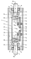
- a pressure cylinder is provided with an axis that can be changed in shape, that the cylinder consists of a cylindrical outer jacket, the opposite ends of which are rotatably mounted on a central shaft, that actuating devices are provided in the interior of said jacket, to give a certain deflection to the axis of the casing, said actuating means being received by a central part of the central shaft and having levers which are articulated to the central part and around their articulation point, under the influence of thrust devices, which are mounted on said central part are pivotable, that the pivotable lever with the inner jacket surface are operatively connected via rollers which are taken up by the levers.
- Each of the ends of the jacket 2 is connected to an annular body 6, the outer surface of which is non-positively connected to the inner cylindrical surface 7 of the jacket.
- Each ring body 6 has a bore 8 on each outwardly facing surface, the bottom of which is penetrated by an axial bore 9. This bore is rotatable and penetrated with radial play by the corresponding pin 4, the outer surface of which is connected to the inner ring of a radial ball bearing 10, which is non-positively arranged in the interior of the bore 8, about the jacket 2 rotatable relative to the shaft 3 to record.
- each pin 4 protrudes from the jacket 2 and forms a support for the cylinder 1, while the other end continues in the interior of the casing 2 and is in operative connection with a bore 11 which is incorporated into a wall 12 of the housing middle piece , with which each end pin 4 is firmly connected.
- the cylinders 15 are arranged essentially radially with respect to the sleeve 2 and are provided in the vicinity of the inwardly directed ends of the corresponding end pins 4. Between the piston-cylinder units 15, the longitudinal rib 14 has a projection 19, which also extends in the radial direction towards the casing 2, from a free side of the longitudinal rib 14, which is opposite the wall 13.
- each lever 21 has an essentially round cross-sectional shape and is non-positively connected to the inner surface of the inner ring of a radial ball bearing 22, the outer ring of which is pressed against the surface 7 of the casing 2 by the piston rod 16 and the corresponding lever 21.
- the pressure fluid can be supplied to the cylinder 15, either directly via pressure lines (P), which extend through the pins 4 to the bores 18, or the entire chamber defined by the jacket 2 and the ring body 6 can be pressurized will.
- P pressure lines
- An increase in pressure inside the cylinder 15 corresponds to an outward displacement of the piston rods 16 and an outward pivoting of the levers 21. This movement resists the jacket 2 and rigidly opposes the shaft 3. A pivoting of the ball bearings 22 to the outside is made possible by an outward deflection of the casing 2 in the middle thereof with respect to the shaft 3.
Landscapes
- Engineering & Computer Science (AREA)
- Mechanical Engineering (AREA)
- General Engineering & Computer Science (AREA)
- Rolls And Other Rotary Bodies (AREA)
- Pens And Brushes (AREA)
- Perforating, Stamping-Out Or Severing By Means Other Than Cutting (AREA)
- Rotary Presses (AREA)
Applications Claiming Priority (2)
| Application Number | Priority Date | Filing Date | Title |
|---|---|---|---|
| IT67238/82A IT1155103B (it) | 1982-03-03 | 1982-03-03 | Cilindro di pressione con asse a configurazione variabile |
| IT6723882 | 1982-03-03 |
Publications (1)
| Publication Number | Publication Date |
|---|---|
| EP0087729A1 true EP0087729A1 (fr) | 1983-09-07 |
Family
ID=11300739
Family Applications (1)
| Application Number | Title | Priority Date | Filing Date |
|---|---|---|---|
| EP83101695A Withdrawn EP0087729A1 (fr) | 1982-03-03 | 1983-02-22 | Cylindre d'impression à axe de forme variable |
Country Status (4)
| Country | Link |
|---|---|
| US (1) | US4510865A (fr) |
| EP (1) | EP0087729A1 (fr) |
| JP (1) | JPS58166052A (fr) |
| IT (1) | IT1155103B (fr) |
Cited By (2)
| Publication number | Priority date | Publication date | Assignee | Title |
|---|---|---|---|---|
| EP1333123A1 (fr) * | 2002-02-05 | 2003-08-06 | Eduard Küsters Maschinenfabrik GmbH & Co. KG | Procédé et dispositif d'amortissement actif dans un dispositif de traitement d'une bande en mouvement continu |
| EP1333122A3 (fr) * | 2002-02-05 | 2004-08-18 | Eduard Küsters Maschinenfabrik GmbH & Co. KG | Méthode d'amortissement actif de vibrations |
Families Citing this family (11)
| Publication number | Priority date | Publication date | Assignee | Title |
|---|---|---|---|---|
| US5490458A (en) * | 1994-04-13 | 1996-02-13 | Bryce Corporation | Printing press cylinder assembly |
| US5453069A (en) * | 1994-09-01 | 1995-09-26 | Snyder Manufacturing Inc. | Working roller with variable deflection control |
| CH690077A5 (de) * | 1995-05-05 | 2000-04-14 | Pretto Escher Wyss De | Presswalze und Maschine mit Presswalze. |
| FI103071B1 (fi) * | 1997-08-19 | 1999-04-15 | Valmet Corp | Taivutettava tela rainamaista materiaalia varten |
| DE10313443B4 (de) * | 2003-03-26 | 2006-08-24 | Koenig & Bauer Ag | Zylinder mit Welle und drehbarem Mantel |
| FI121825B (fi) * | 2005-09-01 | 2011-04-29 | Metso Paper Inc | Levitystela |
| DE102005044956A1 (de) * | 2005-09-20 | 2007-03-22 | Voith Patent Gmbh | Breitstreckwalze |
| DE102005044958A1 (de) * | 2005-09-20 | 2007-03-22 | Voith Patent Gmbh | Breitstreckwalze |
| DE102005044957A1 (de) * | 2005-09-20 | 2007-03-22 | Voith Patent Gmbh | Breitstreckwalze |
| JP4701067B2 (ja) * | 2005-10-20 | 2011-06-15 | 東芝機械株式会社 | ロール |
| US20120097057A1 (en) * | 2010-10-22 | 2012-04-26 | Manroland Ag | Printing unit and a printing press and printing roller or impression cylinder of a printing press |
Citations (4)
| Publication number | Priority date | Publication date | Assignee | Title |
|---|---|---|---|---|
| GB893426A (en) * | 1961-01-26 | 1962-04-11 | Karl Marx Stadt Maschf | Improvements in or relating to pressure rollers for calenders, foulards or the like machines |
| US3119324A (en) * | 1960-08-29 | 1964-01-28 | Beloit Iron Works | Controlled deflection roll |
| CH383087A (de) * | 1960-05-11 | 1964-10-15 | Benninger Ag Maschf | Biegungsarme Walze |
| GB2061459A (en) * | 1979-10-09 | 1981-05-13 | Roland Man Druckmasch | Bending rollers |
Family Cites Families (6)
| Publication number | Priority date | Publication date | Assignee | Title |
|---|---|---|---|---|
| US1358843A (en) * | 1917-01-17 | 1920-11-16 | Grass William | Printing-press |
| US2583889A (en) * | 1948-02-17 | 1952-01-29 | Schoonenberg Pancras Johannes | Expansible printing cylinder for rotary multicolor printing |
| AT243292B (de) * | 1962-01-17 | 1965-11-10 | Winkler Fallert & Co Maschf | Bewegungseinrichtung für Drucksegmente in Offsetzylindern |
| BE664784A (fr) * | 1965-06-01 | 1965-12-01 | ||
| US3638292A (en) * | 1969-10-29 | 1972-02-01 | Vlaanderen Machine Co Van | Roll for applying uniform pressure |
| DE2742002A1 (de) * | 1977-09-17 | 1979-03-29 | Ludwig Zboron | Tiefdruckzylinder |
-
1982
- 1982-03-03 IT IT67238/82A patent/IT1155103B/it active
-
1983
- 1983-02-22 EP EP83101695A patent/EP0087729A1/fr not_active Withdrawn
- 1983-02-24 US US06/469,526 patent/US4510865A/en not_active Expired - Fee Related
- 1983-03-03 JP JP58035208A patent/JPS58166052A/ja active Pending
Patent Citations (4)
| Publication number | Priority date | Publication date | Assignee | Title |
|---|---|---|---|---|
| CH383087A (de) * | 1960-05-11 | 1964-10-15 | Benninger Ag Maschf | Biegungsarme Walze |
| US3119324A (en) * | 1960-08-29 | 1964-01-28 | Beloit Iron Works | Controlled deflection roll |
| GB893426A (en) * | 1961-01-26 | 1962-04-11 | Karl Marx Stadt Maschf | Improvements in or relating to pressure rollers for calenders, foulards or the like machines |
| GB2061459A (en) * | 1979-10-09 | 1981-05-13 | Roland Man Druckmasch | Bending rollers |
Cited By (2)
| Publication number | Priority date | Publication date | Assignee | Title |
|---|---|---|---|---|
| EP1333123A1 (fr) * | 2002-02-05 | 2003-08-06 | Eduard Küsters Maschinenfabrik GmbH & Co. KG | Procédé et dispositif d'amortissement actif dans un dispositif de traitement d'une bande en mouvement continu |
| EP1333122A3 (fr) * | 2002-02-05 | 2004-08-18 | Eduard Küsters Maschinenfabrik GmbH & Co. KG | Méthode d'amortissement actif de vibrations |
Also Published As
| Publication number | Publication date |
|---|---|
| IT8267238A0 (it) | 1982-03-03 |
| US4510865A (en) | 1985-04-16 |
| JPS58166052A (ja) | 1983-10-01 |
| IT1155103B (it) | 1987-01-21 |
Similar Documents
| Publication | Publication Date | Title |
|---|---|---|
| EP0043119B1 (fr) | Cylindre presseur à réglage de la flexion | |
| DE3239266C2 (fr) | ||
| DE2826316C2 (de) | Durchbiegungseinstellwalze | |
| DE2254392A1 (de) | Druckwalze | |
| EP0087730A1 (fr) | Cylindre d'impression à axe longitudinal de forme variable | |
| EP0087729A1 (fr) | Cylindre d'impression à axe de forme variable | |
| DE3877763T2 (de) | Walze. | |
| DE3909556C2 (de) | Beheizbare Durchbiegungseinstellwalze | |
| DE3138365A1 (de) | Durchbiegungseinstellwalze | |
| DE69311577T2 (de) | Walzenmechanismus zur axialen positionierung des walzenmantels einer selbstbelastenden durchbiegungsausgleichswalze | |
| CH615487A5 (fr) | ||
| AT392661B (de) | Presswalze, deren durchbiegung einstellbar ist | |
| DE3124616C2 (de) | Walzenanordnung mit einer Durchbiegungseinstellwalze | |
| DE2510852A1 (de) | Vorrichtung zum aufschlagen von fasermaterial | |
| DE1287933B (de) | Einrichtung zum Andrücken der Zylindertrommel einer Axialkolbenmaschine an deren Steuerspiegel | |
| DE2238582A1 (de) | Axialkolbenmaschine | |
| DE2700379C3 (de) | Walze mit regulierbarer Durchbiegung | |
| EP1588051A1 (fr) | Machine a piston, arbre et palier a roulement pour machine a piston | |
| DE3024575A1 (de) | Presswalze mit durchbiegungsausgleich | |
| DE2660470C2 (de) | Druckluftbetriebene Hydraulikpumpe | |
| DE1949611A1 (de) | Axialkolbenmaschine | |
| DE2903811A1 (de) | Walze, insbesondere presswalze fuer papiermaschinen | |
| DE2853493A1 (de) | Taumelscheibenpumpe oder -motor | |
| DE2434631C2 (de) | Radialkolbenmaschine für hohe Arbeitsdrücke | |
| DE1453573C (de) | Hydraulische Neigungsverstelleinrichtung fur die Taumel oder Schiefscheibe einer Druckflussigkeits Axialkolbenmaschine |
Legal Events
| Date | Code | Title | Description |
|---|---|---|---|
| PUAI | Public reference made under article 153(3) epc to a published international application that has entered the european phase |
Free format text: ORIGINAL CODE: 0009012 |
|
| AK | Designated contracting states |
Designated state(s): CH DE FR GB LI SE |
|
| 17P | Request for examination filed |
Effective date: 19840507 |
|
| STAA | Information on the status of an ep patent application or granted ep patent |
Free format text: STATUS: THE APPLICATION HAS BEEN WITHDRAWN |
|
| 18W | Application withdrawn |
Withdrawal date: 19850925 |
|
| RIN1 | Information on inventor provided before grant (corrected) |
Inventor name: MOLINATTO, BRUNO |